0-7
CONFIDENTIAL
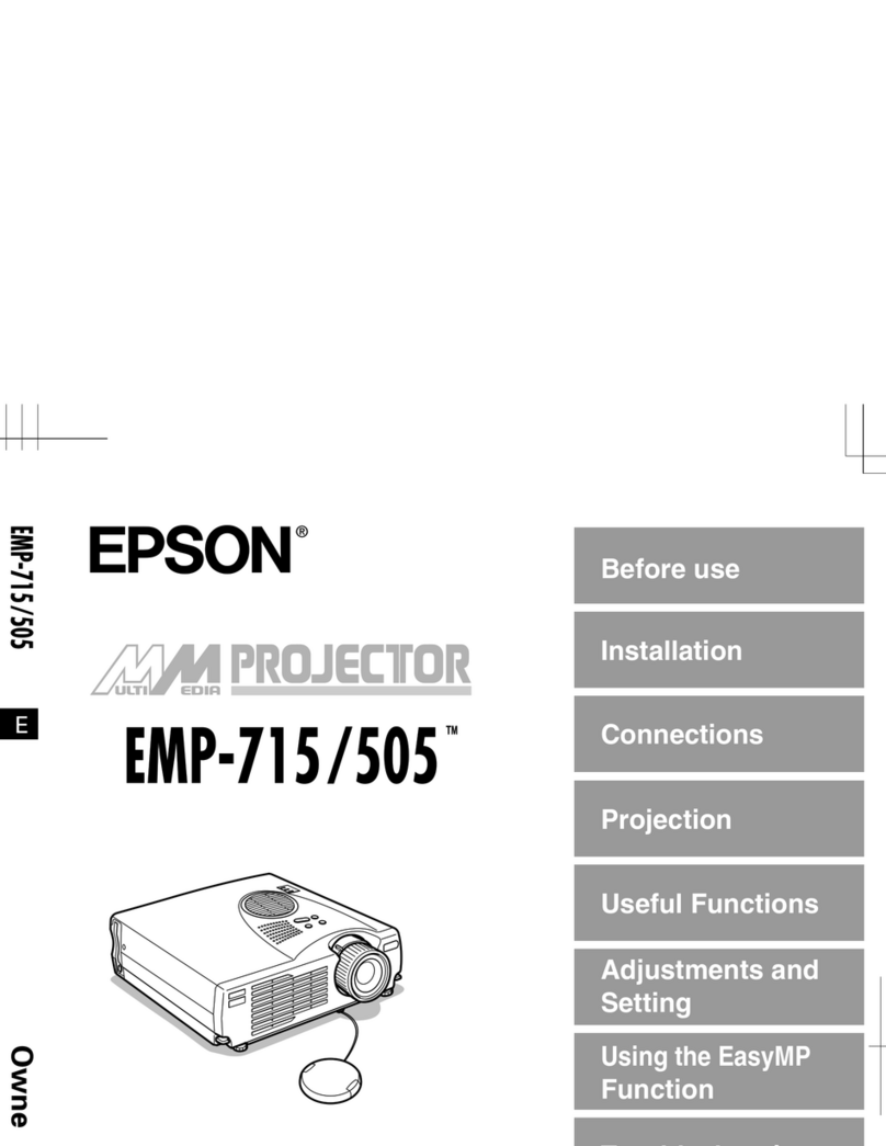
EMP-1825/EMP-1815/EMP-1810
SEIKO EPSON Revision:C
Chapter 1 Product Specifications
1.1 Product Features .....................................................................................1-2
1.1.1 Features of the Projector...............................................................1-2
1.2 Specifications...........................................................................................1-3
1.3 External Views.........................................................................................1-4
1.4 Dimensions for Ceiling Mount..................................................................1-6
Chapter 2 Theory of Operation
2.1 Internal Components................................................................................2-2
2.2 Hardware Overview .................................................................................2-3
2.2.1 Electrical Circuit Components.......................................................2-4
2.2.2 Optical Engine...............................................................................2-6
2.3 Temperature Control................................................................................2-7
2.3.1 Sensors and Switches...................................................................2-7
Chapter 3 Troubleshooting
3.1 Before Carrying Out Troubleshooting......................................................3-2
3.1.1 Troubleshooting Tools and Equipment..........................................3-2
3.2 Basic Information on Troubleshooting .....................................................3-3
3.2.1 LED Indicators...............................................................................3-3
3.2.2 Cable Connection and Projector’s Status......................................3-6
3.3 Troubleshooting.......................................................................................3-9
3.3.1 Basic Checking Flowchart.............................................................3-9
3.3.2 Abnormality Check......................................................................3-10
3.3.3 Exterior Check.............................................................................3-11
3.3.4 Connection Check.......................................................................3-12
3.3.5 Power ON/OFF & Initialization Check.........................................3-14
3.3.6 Image Display & Quality Check...................................................3-15
3.3.7 Audio I/O’s Check........................................................................3-17
3.3.8 Lens Shutter’s Operation Check .................................................3-18
3.3.9 Control Panel’s Operation Check................................................3-19
3.3.10 RC & Projector’s Operation Check..............................................3-20
3.3.11 Wireless/Wired LAN’s Operation Check (EMP-1825/1815 only).3-21
Chapter 4 Disassembly/Assembly
4.1 Overview..................................................................................................4-2
4.1.1 Precautions ...................................................................................4-2
4.1.2 Precautions which must be taken when servicing.........................4-3
4.1.3 Safety precautions.........................................................................4-3
4.1.4 Tools and Equipment ....................................................................4-4
4.1.5 Precautions for Optical Engine and Main (MA) Board...................4-5
4.2 Projector Disassembly and Assembly......................................................4-6
4.3 Removing Exterior Parts/Components...................................................4-10
4.3.1 Removing the AS Lamp Unit.......................................................4-10
4.3.2 Removing the Air Filter Assy.......................................................4-11
4.3.3 Removing the Front Foot Unit/Rear Foot/Rubber Foot...............4-12
4.3.4 Removing the IF-IM Case/Upper Case Unit AJ...........................4-13
