ERAE Electronics Industry elt3220 User manual

ServiceManual
ServiceManual
32inch
32inch
LCDTV
Liquid Crystal Display
Quality Assurance Dept.
Quality Assurance Dept.

CONTENTS
CONTENTS
vSPECIFICATION
SPECIFICATION
.. 3
.. 3
v
vELECTRICALINSPECTION OF LCD PANEL
ELECTRICALINSPECTION OF LCD PANEL
.. 4
.. 4
v
vMODULEPRECAUTIONS
MODULEPRECAUTIONS
.. 8
.. 8
v
vTROUBLESHOOTING
TROUBLESHOOTING
11
11
v
vREPLACEMENTMETHOD OFPARTS
REPLACEMENTMETHOD OFPARTS
15
15
v
vFIRMWARE DOWNLOADING
FIRMWARE DOWNLOADING
... 22
... 22
v
vA/S SPARE PARTS
A/S SPARE PARTS
.
.
... 25
... 25
Quality Assurance Dept.
Quality Assurance Dept.
2/26

uSPECIFICATION
qTV
1.Input Signal:
PAL,SECAM,SD, HD,VGA~SXGA
2.Tuner :PAL, SECAM
3.Input Voltage :AC100V ~240V,@50/60Hz,3.5A(MAX)
4.Power Consumption:125W(Typical)
5.LCD Module:V320 (CMO)
6.Feature:
-AV Input-Component1Input (DVD)
-Component2Input (DTV)-D-SUB (Analog RGB 15PIN)
-DigitalRGB (DVI-D)-S-video2input
-S-Video1 Input-Composite1 Input
-Composite2 Input -Headphone
-SCART1Input (Full)-SCART2Input (Half)
-Tuner (PAL, SECAM)-AudioInput (Composite,Component1/2,S-Video,PC)
-RS-232C(9pin),TCP/IPSupport (0~254set)
7.Function: ARC,PIP,PBP (4:3,16:9),MTS,TTX
Quality Assurance Dept.
Quality Assurance Dept.
3/26

uElectricalInspectionofLCDPanel
Quality Assurance Dept.
Quality Assurance Dept.
4/26
(1)TheDefinitionoftheDotDefect:
Ifthe sizeof dot defect islarge than singledot,it canberegardedasone dot defect.
a)Bright dot:Dot appearsinbright display andthe sizeisfixedinblack pattern.
(It excludesthe particleissueandCFdefect.)
b)Dark dot:Dotappearsindark display andthe sizeisfixedinpurered,green,bluepattern.
(It excludesthe particleissue.)
c)2dot adjacent =1pair =2pair, the phenomenonisshownasbelow:
2 dot adjacent 2 dot adjacent
2 dot adjacent
(Vertical) 2 dot adjacent
(Slant)
uElectricalInspectionofLCDPanel
Quality Assurance Dept.
Quality Assurance Dept.
5/26
Not allowableFunctionalfailure(V-line/H-line/Cross line etc.)
Judgedby 3% ND Filter in50%gray pattern.
(Ifbothcustomer andCMOagree mutually,
CMOwill set uplimit sampleandapply tothe
criteria withthe customer.
Mura
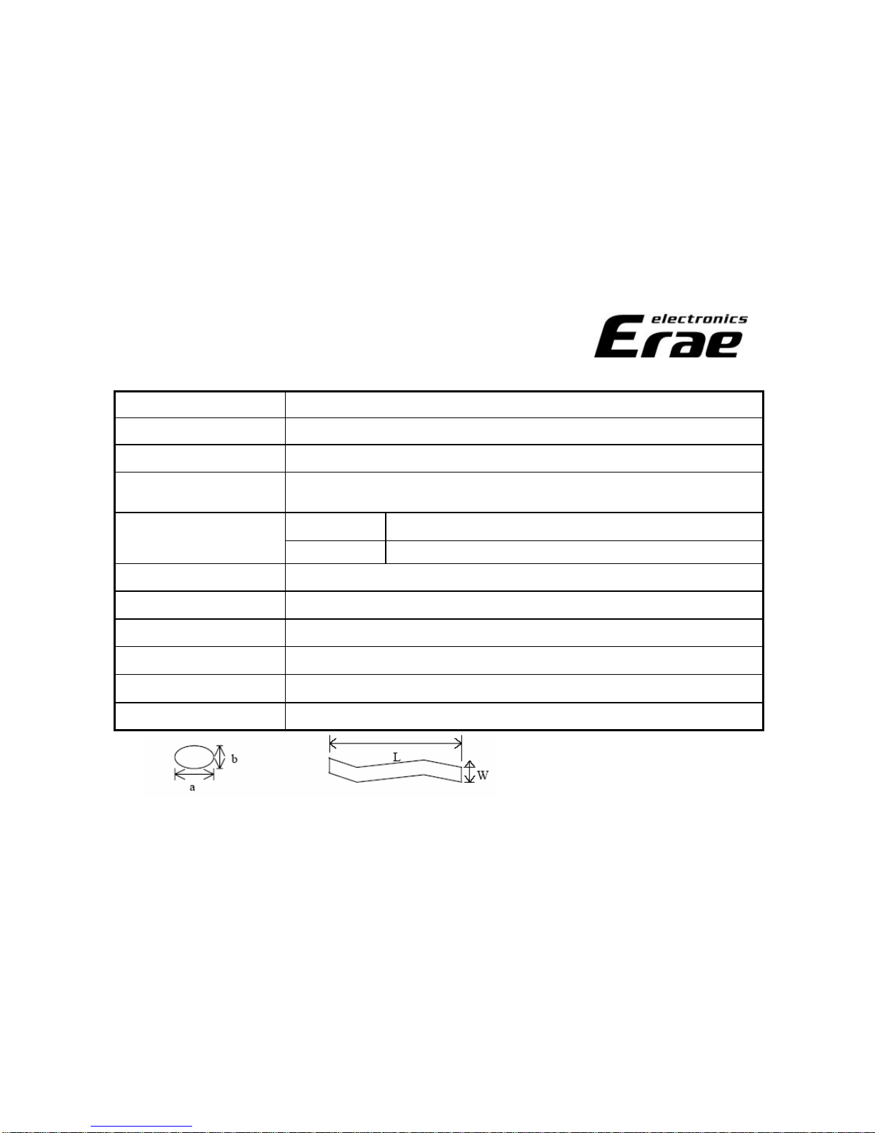
0.15<W 0.25mm,0.3<L 10mm,N 4Foreign Black/ White/ Bright Line
0.5<D 1.2mm,N 10Foreign Black/ White/ Bright spot
N 7Totalbright anddark dot
L ≥5mmMinimum DistanceBetween Dark dots
N 03dotsadjacent or more
N 22dotsadjacent
N 7Random
Dark dot
L ≥5mmMinimum DistanceBetween Bright dots
N 03dotsadjacent or more
N 02dotsadjacent
N 2Random
Bright dot
StandardItem
uElectricalInspectionofLCDPanel
Quality Assurance Dept.
Quality Assurance Dept.
6/26
0.3<D 1.2mm,N 10
Dent/Air Bubble
0.15<W 0.25mm,0.3<L 10.0mm,N 4.
Polarizer Scratches
The stain,whichcan’t bewipedoff,isnot permitted.
StainonPolarizer
Out of spec.isnot permitted.
Outline size
Oxidized/rusty connector isnot permitted.
Connector
Incorrect position,missedlabelisnot permitted.
Tape/Label
The crack isnot permitted.Crack
Nodisplay of backlight unitisnot permitted.Break down
Backlight
Incompleteassembly isnot permitted.
Metalframe
(Bezel)
Broken cable,burnedconnector isnot permitted.
CCFL cable
Missed,incomplete,or deformedassembly isnot permitted.
Screw
StandardItem
D=(a+b)/2 W:width, L:length
uElectricalInspectionofLCDPanel
Quality Assurance Dept.
Quality Assurance Dept.
7/26
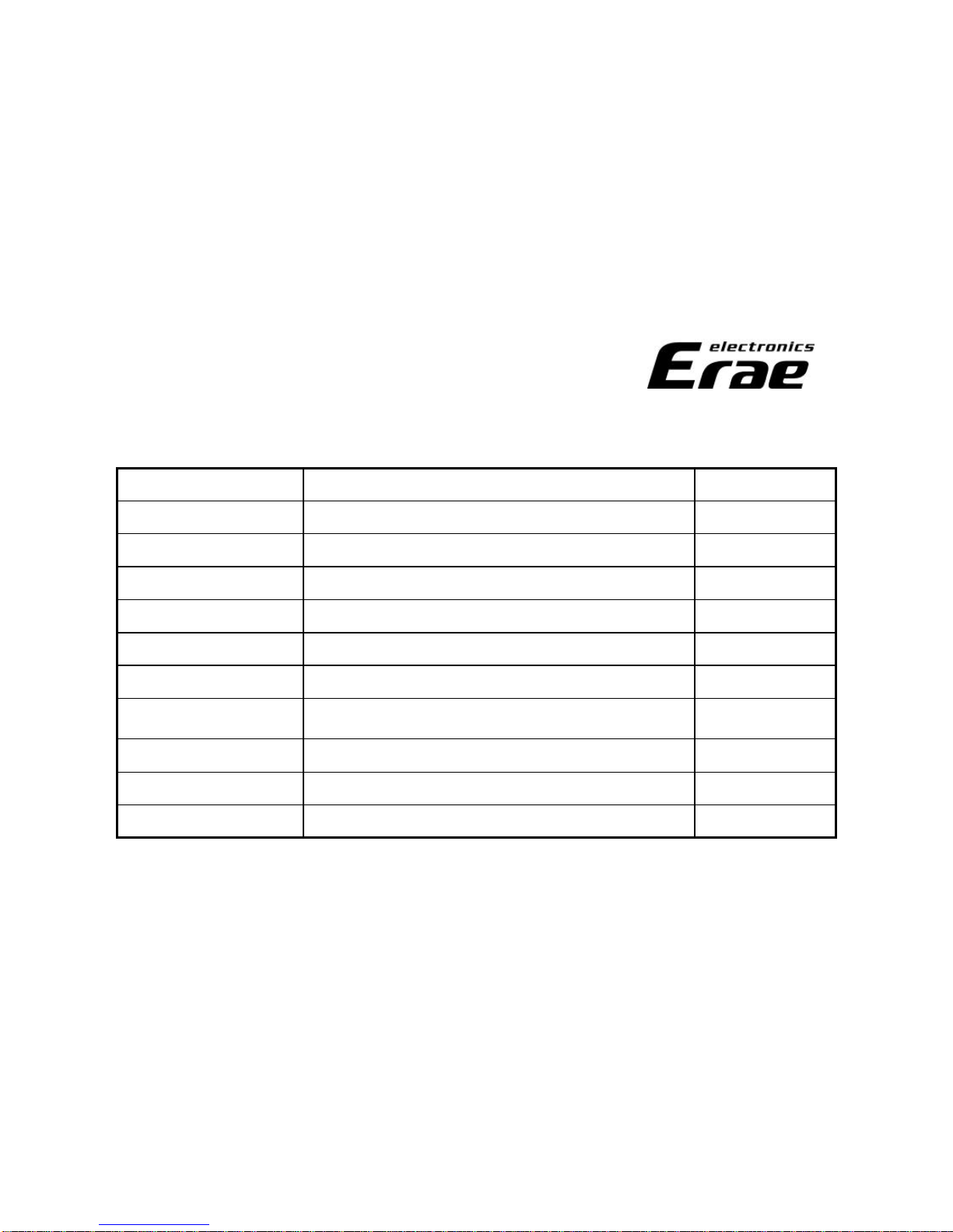
-ClassificationTable ofdefects
MinorPolarizer bubbleappearsindisplayPolarizer bubble
MinorUniformility isappearedindisplayMura
MinorForeign materialappearsindisplayForeign material
MinorPolarizer isdamagedonthe surface
ScratchandDent on
polarizer
MinorBright dot,dark Dot or dotadjacent appear indisplayDotsdefect
MajorAbnormalsignaloutputsindisplayIrregular display
MajorNosignaloutputsindisplayNodisplay
MajorAbnormalcross line appearsindisplayCross line
MajorAbnormalline appearsinhorizontaldirectionHorizontalline
MajorAbnormalline appearsinverticaldirectionVerticalline
Defect typeDescriptionInspection Item
uModule Precautions
1.GENERAL PRECAUTIONS
1.1Handling
(a)When the moduleisassembled.Itshouldbeattachedtothe system firmly using every mounting holes.
Be carefulnot totwist andbendthe modules.
(b)Refrainfrom strong mechanicalshock and/or any forcetothe module.Inadditiontodamage,thismay
causeimproper operationor damage tothe moduleandCCFT back-light.
(c)Notethat polarizersarevery fragileandcouldbeeasily damaged.Donot press or scratchthe surface
harder thana HBpencillead.
(d)Wipeoff water dropletsor oilimmediately. Ifyouleavethe dropletsfor a longtime,staining and
discolorationmay occur.
(e)Ifthe surfaceofthe polarizer isdirty,cleanit using someabsorbent cottonorsoft cloth.
(f)The desirablecleanersarewater,IPA(Isopropylalcohol)or Hexane.Donot useKetonetypematerials
(ex.Acetone),Ethylalcohol,Toluene,EthylacidorMethylchloride.It might permanent damage tothe
polarizer duetochemicalreaction.
(g)Iftheliquidcrystalmaterialleaksfrom the panel,itshouldbekept away from the eyesor mouth.In
caseof contact withhands,legsorclothes,it mustbewashedaway thoroughly withsoap.
(h)Protect the modulefrom static,itmay causedamage tothe CMOS gateArray IC.
Quality Assurance Dept.
Quality Assurance Dept.
8/26

(i)Usefinger-stallswithsoft glovesinorder tokeep display cleanduring the incoming inspectionand
assembly process.
(j)Donot disassemblethemodule.
(k)Donot pull or foldthe lamp wire.
(l)Donot adjustthe variableresistor whichislocatedonthe module.
(m)Protectionfilm for polarizer onthe moduleshallbeslowly peeledoff just beforeusesothat the
electrostaticcharge canbeminimized.
(n)Pinsof I/Fconnector shallnot betoucheddirectly withbarehands.
1.2Storage
(a)Donot leave the moduleinhigh temperature,andhigh for a long time.It ishighly recommendedto
storethe modulewithtemperaturefrom0to35°Candrelative humidity of less than70%.
(b)Donot storethe TFT-LCD moduleindirect sunlight.
(c)The moduleshallbestoredina dark place.It isprohibitedtoapply sunlight or fluorescentlight
during the store.
Quality Assurance Dept.
Quality Assurance Dept.
9/26

1.3Operation
(a)Donot connect, disconnect the moduleinthe “Power On”condition.
(b)Power supply shouldalwaysbeturnedon/off by “Power on/off sequence”.
(c)Modulehashigh frequency circuits.Sufficient suppressiontothe electromagneticinterferenceshall
bedone by system manufactures. Grounding andshielding methods may beimportant tominimize
the interference.
(d)The cablebetween theback-light connector anditsinverter power supply shallbea minimizedlength
andbeconnecteddirectly.The longer cablebetween theback-light andthe inverter may cause
lowerluminanceof lamp (CCFT)andmay requirehigher startup voltage(Vs).
1.4Others
(a)Ultra-violet ray filter isnecessary for outdoor operation.
(b)Avoidcondensationof water.Itmay result inimproper operationor disconnectionof electrode.
(c)Donot exceedthe absolutemaximum rating value.(the supply voltage variation,input voltage
variation,variationinpart contentsandenvironmentaltemperature,andsoon)Otherwisethe
modulemay bedamaged.
(d)Ifthe moduledisplaysthe samepatterncontinuously for a long periodof time,It canbethesituation
when the image “Sticks”tothe screen.
(e)Thismodulehasitscircuitry PCB’sonthe rear sideandshouldbehandledcarefully inorder not to
bestressed.Quality Assurance Dept.
Quality Assurance Dept.
10/26
Quality Assurance Dept.
Quality Assurance Dept.
uTroubleShooting
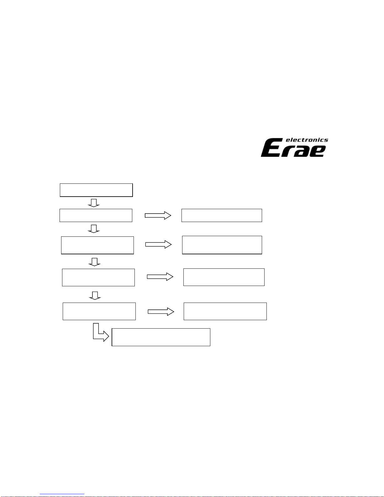
1. NoPower
Nothing output of image.
CheckInput of AC. Connect plugwiththe set.
Check ST-BYLED ON,
MainS/WON.(ACON) Check ACLine Fuseand
ReplacethePSU
Check ST-BYLED COLOR ReplacetheA/D BOARD.
Check theset condition
after dc power on. Check theIRboardorA/D
andreplacethedefect B/D.
Confirmthe Nodisplaysection.
Normal Abnormal
Normal
Abnormal
Normal
Abnormal
YellowLED
RedLED
2
1
11/26
uTroubleShooting
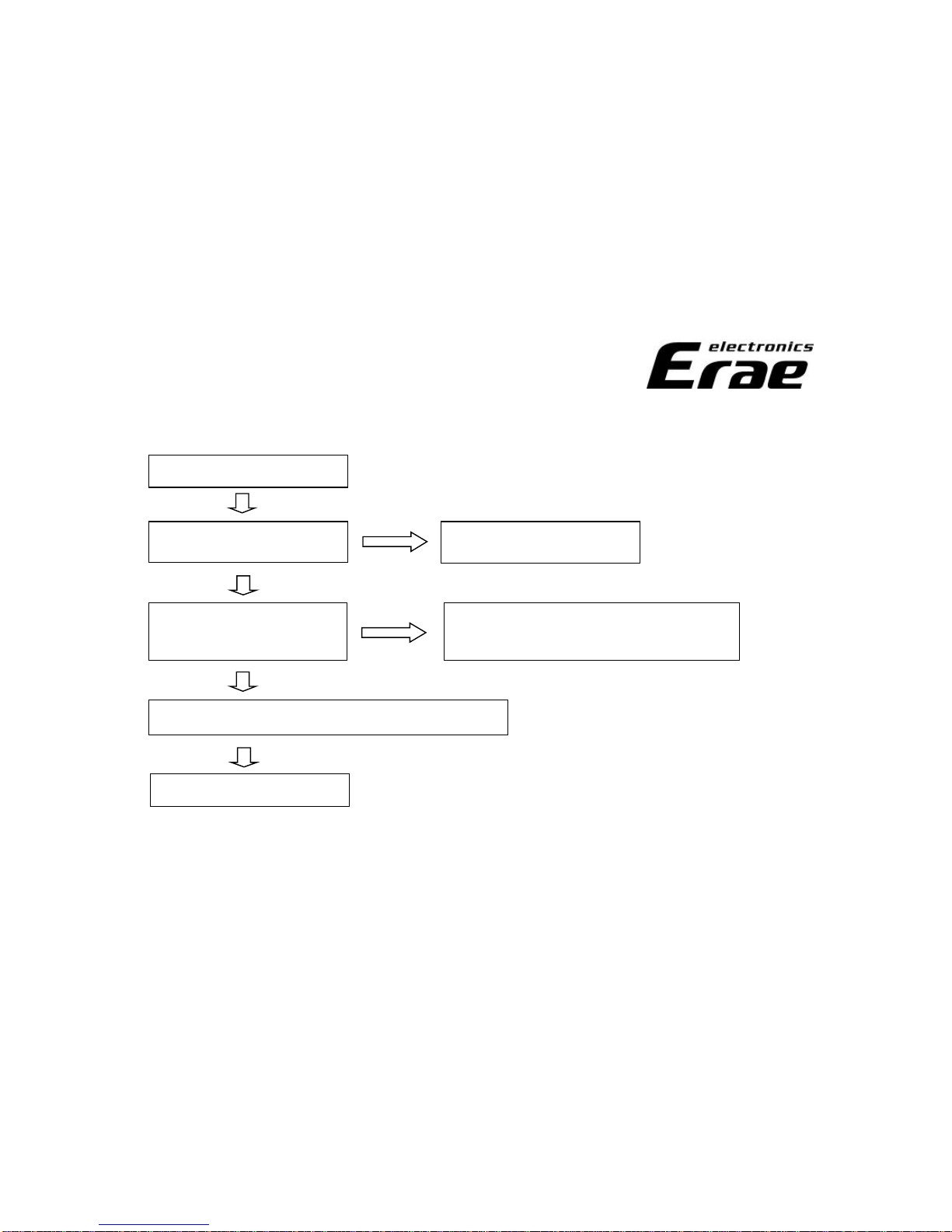
2. NoVideo
AbnormalPicture.
Check theST-BYLED.
Check thefunctionofremote
controller. (power on/off)
Check theinverter cableandLVDS cable.
Check theIRB/D orA/D and
Replacethedefective B/D.(power on/off)
LCD PANEL DEFECTIVE.
Check thePSUor A/D and
Replacethedefective B/D.
Quality Assurance Dept.
Quality Assurance Dept.
Normal
Normal
Normal
Abnormal
Abnormal
12/26
uTroubleShooting
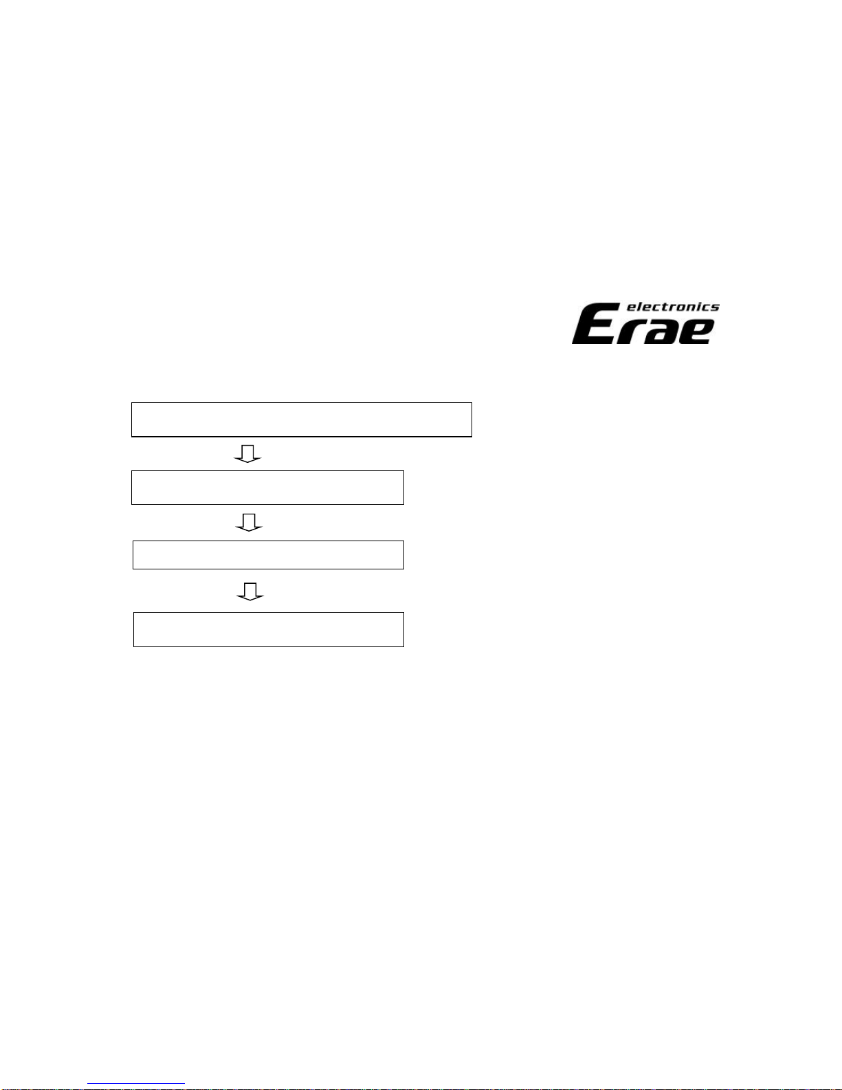
3. NoSound
Check theconnectionof speaker toset after set reset.
Check theconditionafter swap the A/D.
Check theFFCcablebetween I/OandA/D.
Check theconditionafter swap the I/O.
Quality Assurance Dept.
Quality Assurance Dept.
13/26
uTroubleShooting
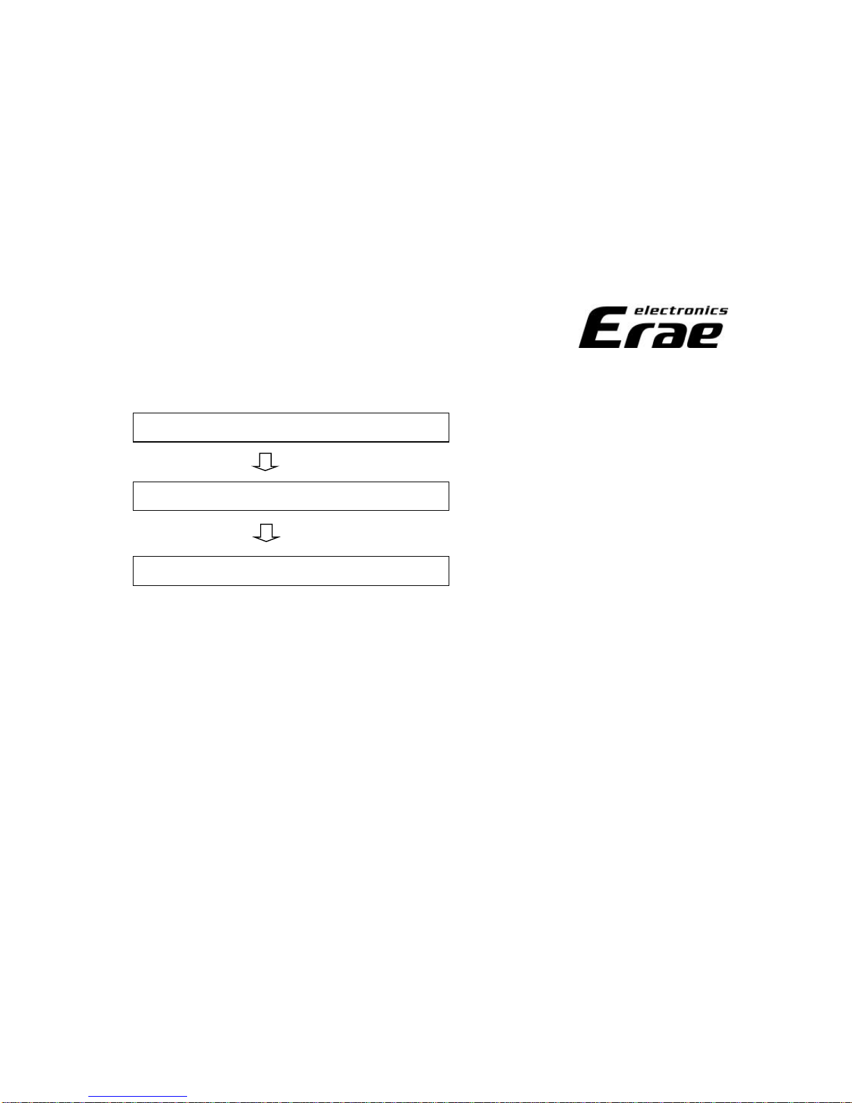
4. Not Searching on TV
Check theFFCcablebetween A/D andTuner B/D.
Check theconditionafter swap the A/D B/D.
Check theconditionafter reset the set.
Quality Assurance Dept.
Quality Assurance Dept.
14/26

Quality Assurance Dept.
Quality Assurance Dept.
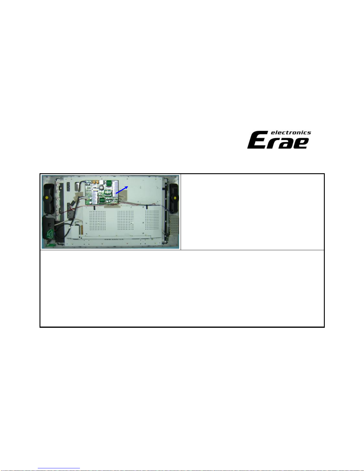
uReplacement Methodofparts
1. PSU
B. Removetheback cover
1.Removetheback cover from the set.
2.Markedscrew’skindby positioncolor.
A.Makeit ready
1.Lay the product downonthe soft mat for
protection.
2.Removethestandfrom the product by taking the
screws(red)out asper the picture.
3.Keep thestandaway from any possiblescratches.
4.Locatethe eliminatedscrewsinsafe for later use.
15/26
BHM 5X16
ZB
Torque
10±1kgf.㎝
BHM
5X10 ZB
BHM
4X10 ZB
Torque
10±1kgf.㎝
BHTT
4X10 ZB
Torque
7±1kgf.㎝
Quality Assurance Dept.
Quality Assurance Dept.
D. CheckPoints
1.Insulator shouldbeplacedunder the PSU,when PSUisfixedonthe set.
2.Doublecheck the connectionof cablebeforereassembling.
C. Replace thenewPSU
1.Removethewirefrom the PSU.
2.Replacethenew PSU.
uReplacement Methodofparts
1. PSU
16/26
PSU

Quality Assurance Dept.
Quality Assurance Dept.
A.Makeit ready
1.Lay the product downonthe soft mat for
protection.
2.Removethestandfrom the product by taking the
screws(red) out asper the picture.
3.Keep thestandaway from any possiblescratches.
4.Locatethe eliminatedscrewsinsafe for later use.
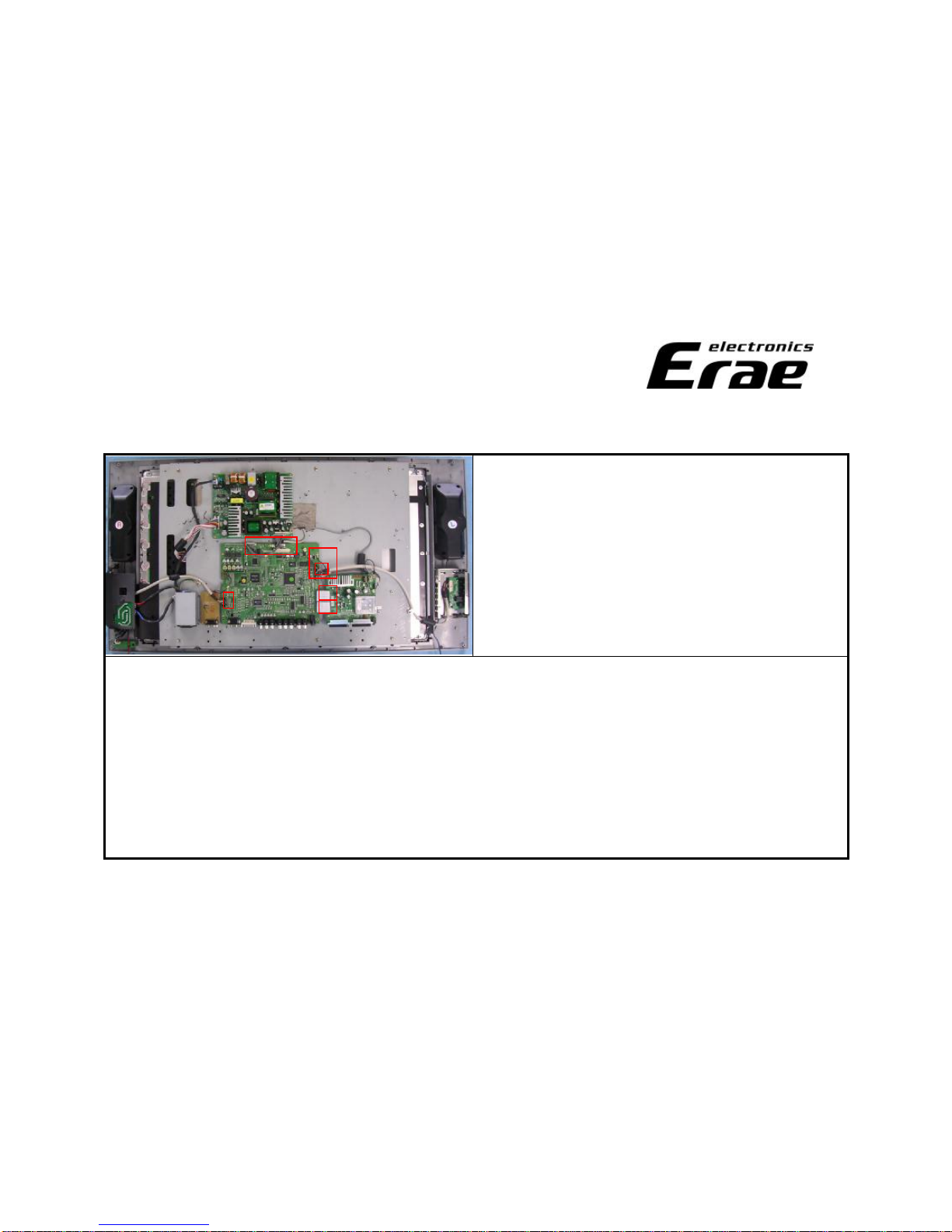
uReplacement Methodofparts
2. A/D (main) Board
17/26
BHM 5X16
ZB
B. Removetheback cover
1.Removetheback cover from the set.
2.Markedscrew’skindby positioncolor.
Torque
10±1kgf.㎝
BHM
5X10 ZB
BHM
4X10 ZB
Torque
10±1kgf.㎝
BHTT
4X10 ZB
Torque
7±1kgf.㎝

Quality Assurance Dept.
Quality Assurance Dept.
3.Locatethe eliminatedscrewsinsafe for later use.
C. Removetheshield mainandjack housing
1.Removetheshieldmainfrom the set.
(BH M 3X6ZN)
2.Removethejack housing from the a/dandtuner
board.
(BH T3X82S ZB,SPECIALWASHER,SPECIAL NUT)
uReplacement Methodofparts
2. A/D (main) Board
18/26
BHM
3X6 ZN
Special
Nut
Special
Washer
BHT3X8
2SZB

Quality Assurance Dept.
Quality Assurance Dept.
uReplacement Methodofparts
2. A/D (main) Board
4.Observe tousesuitablescrewswhen dodisjointing
andassembly.
D. Replace thenewA/D board
1.Removethepower cableandLVDS cablefrom the
defective A/D board.
2.Must observe lest cableshouldbedamagedat FFC
cableseparation.
3.Replacethenew A/D board.
A/DTUNER
BHM
3X6 ZN
19/26
Quality Assurance Dept.
Quality Assurance Dept.
*ExtraCheck Points
1.Check out ifthe sameproblem occurseven after the reassembling.
2.Iffine,commit anaging test noless than10minutes.
3.Apply theinput/output functionof Composite,S-Video,Component AudioandVideo,andcheck outif
they work well.
4.Wear a wrist bandtoprotect staticelectricity when handing
C. Check theCable connection
1.Doublecheck the belowpoints.
-FFCcable24Px50mm
-ACPower Wire
-OSD Wire8P 800mm
-Power Wire12P120mm
-SubA/V wire20P
uReplacement Methodofparts
2. A/D (main) Board
20/26
Table of contents
Other ERAE Electronics Industry LCD TV manuals


