Ergon Crafco BAX 250 User manual

BAX 250
PART MANUAL - 26357
Rev. B

2
Created: 12/11
3
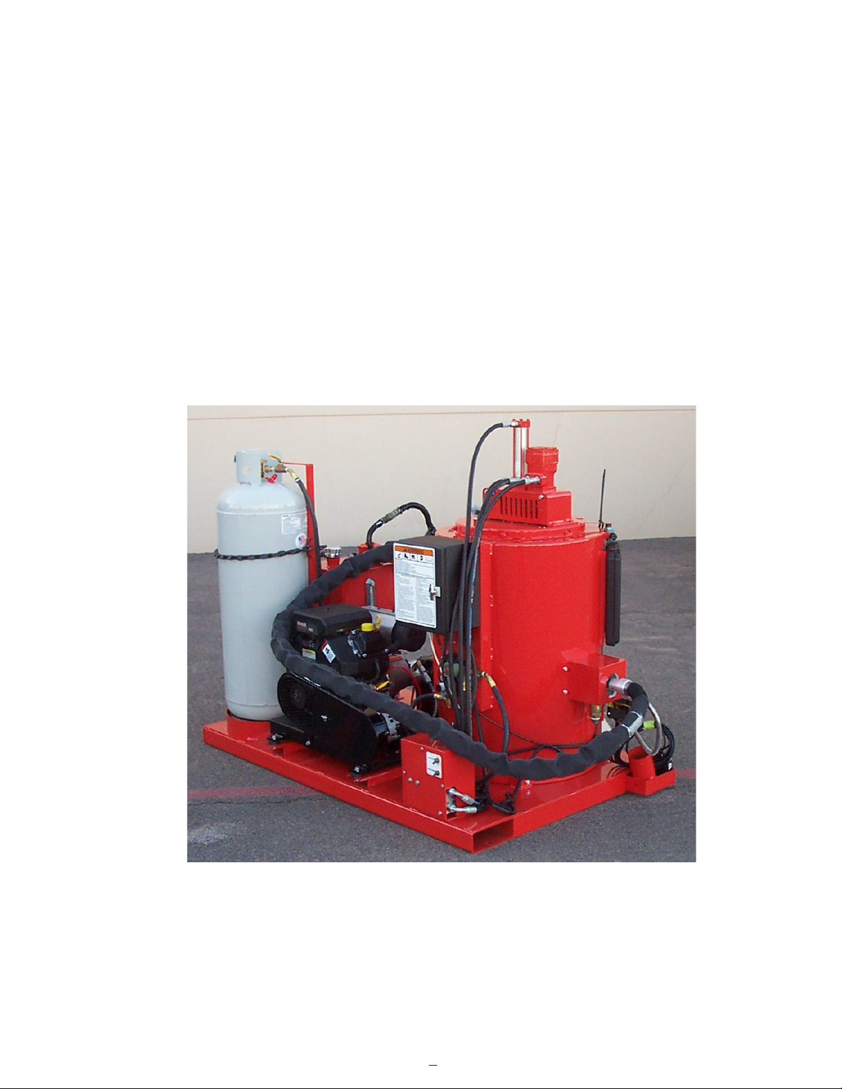
BAX 250
PART NUMBER 55400

4
TABLE OF CONTENTS
BAX 250................................................................................................................................... 5
Safety Precautions.................................................................................................................... 6
Limited Warranty....................................................................................................................... 7
Warranty Claim Instructions....................................................................................................... 8
Specifications............................................................................................................................9
Introduction...............................................................................................................................10
Mounting the Bax 250 Melter......................................................................................................11
Operating Instructions
Machine Start Up/Starting the Engine.................................................................. 12
Heated Hose, Wand, and Controller.................................................................... 12
Starting the Mixer.............................................................................................. 12
Dispensing the Material..................................................................................... 13
Loading the Machine......................................................................................... 14
Shutdown and Clean-out Procedure/Storing Machine............................................ 14
Instructions for Ordering Parts............................................................................ 15
Electric Hose Care and Cautions........................................................................ 15
Hose Transport Instructions................................................................................16
Maintenance
Maintenance Instructions and Chart.................................................................... 17
Temperature Control Calibration.......................................................................... 17
Service Instructions/Recommended Fluids and Lubricants.....................................18
Trouble Shooting
Hose Trouble Shooting - Hose Does Not Heat.......................................................19
Hose Trouble Shooting - Material Does Not Dispense When Pump is Activated...... 20-21
Burner Trouble Shooting.................................................................................... 22
Burner Schematic............................................................................................. 23
Parts
Bax 250 Assembly - Diagram and Parts............................................................. 24-27
Pump/Agitator Motor Assembly - Diagram and Parts........................................... 28-29
Power Pack Assembly - Diagram and Parts........................................................30-31
Control Box Assembly - Diagram and Parts.........................................................32-33
Gas Manifold Assembly - Diagram and Parts.......................................................34-35
Hydraulic Valve Assembly - Diagram and Parts....................................................36-37
Hydraulics Schematic and Parts.........................................................................38-39
LPG Piping Diagram and Parts...........................................................................40-41
Electrical Schematic and Parts...........................................................................42-43

5
BAX 250
This manual is furnished with each new CRAFCO BAX 250. This manual will help your
machine operators learn to run the melter applicator properly and understand its
mechanical functions for trouble-free operation.
Your CRAFCO BAX 250 is designed to give excellent service and save maintenance
expense. However, as with all specially engineered equipment, you can get best results at
minimum costs if:
1. You operate your machine as instructed in this manual.
2. Maintain your machine regularly as stated in this manual.
WARNING: The engine exhaust from this product contains chemicals
known to the State of California to cause cancer, birth defects or other
reproductive harm. Operate in well ventilated area only. Engine exhaust
is deadly.

6
SAFETY PRECAUTIONS
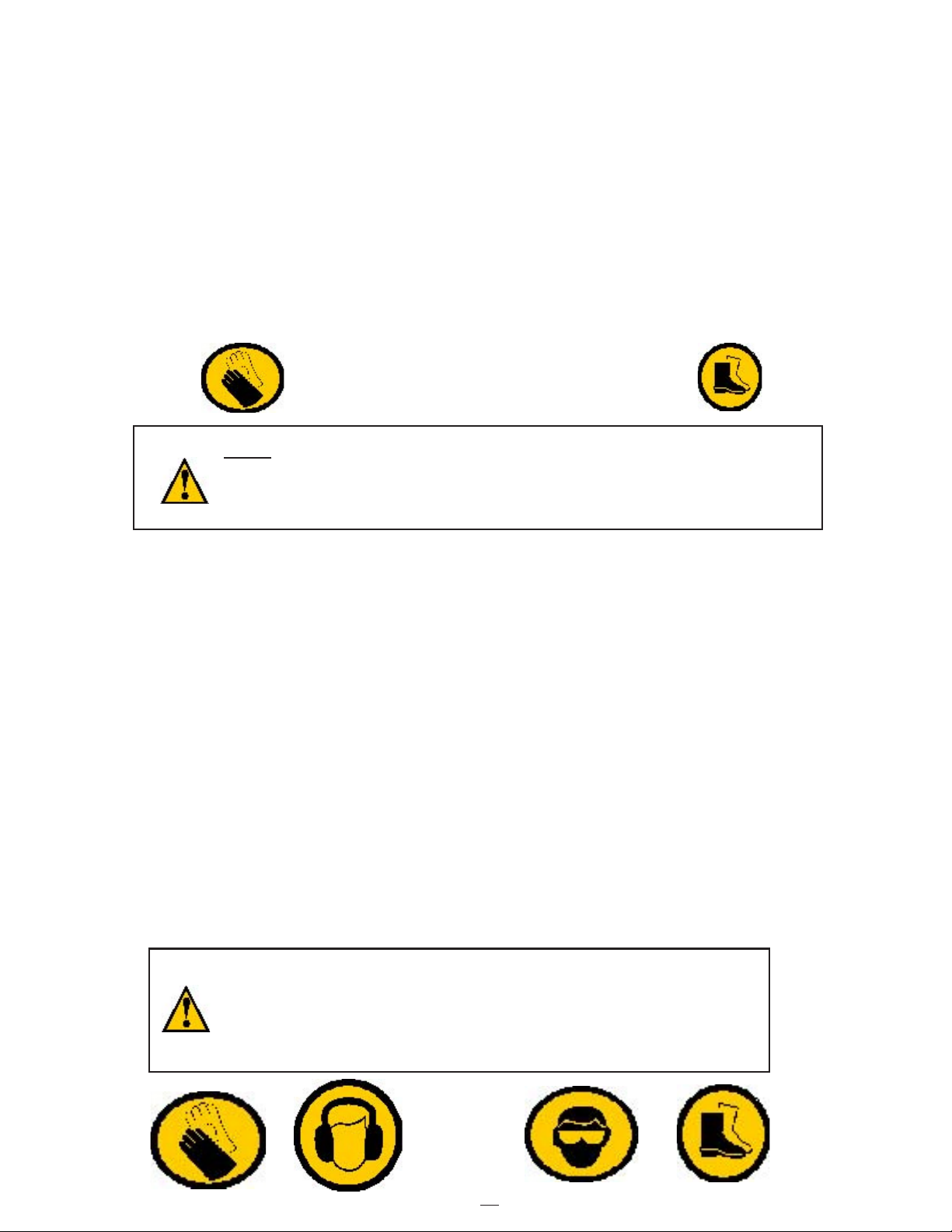
•High operating temperatures of sealant and machine require protective clothing, hard
soled shoes and heat resistant gloves be worn by operator.
•Always wear eye protection.
•Observe all CAUTION AND WARNING signs posted on machine.
•Avoid the entrance of water into any part of the machine.
•Avoid bodily contact with hot sealant material, serious burns may result.
•Read Operator Manual thoroughly before operating machine.
•Make sure operator is familiar with machine operation.
•Do not operate in closed building or confined areas.
•Shut-down burner and engine prior to refilling propane tank.
•When adding solid material to sealant tank, stop mixer, lift lid, place material onto lid and
close lid before restarting mixer. Hot material could splash and cause serious burns if this
procedure is not followed.
•Keep hands, feet, and clothing away from all moving parts.
•Always keep a fire extinguisher near the unit. Maintain extinguisher properly and be
familiar with its use.
•Follow operating instructions for starting and shut-down of burner. Instructions are
mounted on control box.
•Calibrate temperature control prior to initial operation and each 50 hours of operation.
See page 16 step by step instruction.
•Replace any hoses which show signs of wear, fraying, or splitting. Be sure all fittings and
joints are tight and leak-proof.
• Precaution is the best insurance against accidents.
•The BAX 250 Melter should not be left unattended with burner lit.
•Tighten all bolts and screws after every 100 hours of operation.
•Crafco, Inc. assumes no liability for an accident or injury incurred through improper use of
the machine.

7
LIMITED WARRANTY
Crafco, Inc., through its authorized distributor, will replace for the original purchaser free of
charge any parts found upon examination by the factory at Mesa, Arizona, to be
defective in material or workmanship. This warranty is for a period within 60 days of
purchase date, but excludes engine or components, tires, and battery as these items are
subject to warranties issued by their manufacturers.
After 60 days, Crafco, Inc., warrants structural parts, excluding heating system, hydraulic
components, material pump and hoses, applicator valves, and electrical components for a
period of (1) one year from date of delivery. Crafco, Inc., shall not be liable for parts that
have been damaged by accident, alteration, abuse, improper lubrication/maintenance,
normal wear, or other cause beyond our control.
The warranty provided herein extends only to the repair and/or replacement of those
components on the equipment covered above and does not cover labor costs. The
warranty does not extend to incidental or consequential damages incurred as a result of
any defect covered by this warranty.
All transportation and labor costs incurred by the purchaser in submitting or repairing
covered components must be bore by the purchaser.
Crafco, Inc. specifically disavows any other representation, warranty, or liability related to
the condition or use of the product.
WARNING: Use of replacement parts other than genuine Crafco parts
may impair the safety or reliability of your equipment and nullifies any
warranty.

8
WARRANTY CLAIM INSTRUCTIONS
Please follow the instructions stated below when calling in a Warranty Claim. Failure to
follow these procedures may be cause to void the warranty.
1. Call your local Crafco Distributor. If you do not know who your local distributor is,
call a Crafco Customer Service Representative, (Toll Free 1-800-528-8242) for
name, location, and telephone number.
2. On contacting the distributor, be prepared to identify the machine type, model
number, and serial number, also, the date of purchase if available.
3. Should the cause of the malfunction be a defective part, the distributor will advise
you of the procedure to follow for a replacement.
4. The warranty is valid only for parts, which have been supplied or recommended by
Crafco, Inc.
If you have any additional questions regarding warranty repairs and parts, please do not
hesitate to call toll free 1-800-528-8242.
CRAFCO, INCORPORATED
25527 SOUTH ARIZONA AVENUE
CHANDLER, AZ 85248
480-655-8333
Toll Free 1-800-528-8242

9
SPECIFICATIONS
Vat Capacity..................................................................25 Gallons
Melt Capacity................................................................ 20 Gallons/Hour
Tank Construction.........................................................Direct Fired Type Construction
Tank Opening Size....................................................... 18” X 6”
Maximum Heat Input.................................................... Vapor Burner 75,000 BTU’s
Burner and Temperature Control.................................. Automatic - Fail Safe
Engine - Kohler............................................................. Single Cylinder
Model CH-14 - Propane Fueled 20 BHP @ 3,600 rpm
Drive Mechanism..........................................................All Hydraulic Mixer
and Material Pump
Mixer............................................................................. High Speed Two Pitched
Blade Agitator
Dry Weight....................................................................Approximately 1,189 lbs.
Propane Bottle (1)........................................................ 100 lbs.
Generator..................................................................... 24 VAC, 3-PHASE
Hydraulic Tank Capacity...............................................12 Gallons

10
BAX 250 MELTER
INTRODUCTION
The CRAFCO BAX 250 MELTER was developed to melt CRAFCO Brand Sealant.
However, it will work equally well with all road asphalt and federal specification crack or
joint sealant.
DO NOT operate machine without following these instructions:
1. Fill propane tank.
2. Check engine crankcase oil level (refer to Engine Operator’s Manual).
3. Check hydraulic fluid level, at ambient temperature. Add fluid if necessary to bring
to correct level.
4. All toggle switches should be turned “OFF” and all temperature control dials at
minimum settings.
5. Remember that safe operation of this equipment is the operator’s responsibility.
CAUTION:
Extreme care must be used when operating this equipment. Safety is the result
of being careful and paying attention to details. Remember the propane flame is
about 2,200°F. Certain exposed parts of this machine, when operating reach
500°F.; the sealant as high as 400°F. and the hydraulic fluid may reach 200°F.
Always wear protective clothing, hard-soled shoes, and eye protection. Be sure
that all joints and fittings are tight and leak proof. Immediately replace any hose,
which shows any signs of wear, fraying, or splitting. Tighten all bolts, nuts, and
screws every 250 hours.

11
MOUNTING THE BAX 250 MELTER
1. Only mount the unit to a metal truckbed or any other non-flammable surface.
2. Mount unit 3” above the truckbed. Mount with four(4) 1/2” bolts minimum.
3. Leave 15” clear all around machine.
15"
3"
SEALANT AND MARKERS
STORAGE AREA

12
MACHINE START UP
TO START BURNER
1. Open the vent damper.
2. Open LPG tank valve and ball valve at cylinder.
3. Start engine per instruction below.
4. Turn “ON” power toggle switch at control box.
5. Set material temperature at manufacturers recommended temperature.
CAUTION:
If burner does not ignite the first time, turn temperature dial to off. Turn
temperature dial to desired setting. Burner should ignite. If burner still does
not ignite, determine cause of malfunction (see Burner Trouble Shooting Guide
pg. 22).
STARTING THE ENGINE
Choke engine, turn the ignition key to start position. Engine should start. After engine
starts, allow to warm up before using hydraulics or generator.
STARTING THE MIXER
When the sealant material reaches 275oF, engage the mixer by moving the toggle switch to
“ON” (switch located on hydraulic panel.) If the mixer does not move, allow
material to heat longer. Jamming of mixer shaft causes hydraulic oil to overheat and
machine damage could occur. Remember, mixer does not start with melter lid open. The
mixer speed is preset for optimum performance for the factory.
HEATED HOSE, WAND, AND CONTROLLER
CAUTION:
The hose must be up to temperature before dispensing can take place.
IMPORTANT!! DO NOT twist or kink hose. Avoid sharp bends and continuous
twisting. Maintain minimum 10” bend radius. DO NOT exceed 400 degrees!!
DO NOT move or bend hose when cold. Damage may result.
The heated hose supplied with the machine is Teflon lined with a stainless steel overbraid.
It has a heating element which runs down the hose to heat the material within the hose.
The hose is insulated with silicone foam rubber and is covered with a durable rubber outer
covering. The wand has an aluminum tube to protect both the wand and the operator. The
pistol grip actuator is equipped with an electric switch which when depressed sends a
signal to actuate the pump. At the end of the wand, a high temperature elasomeric output valve
is attached. The valve is pressure actuated and opens automatically when fluid pressure is
applied. The wand is equipped with a trigger lock to prevent accidental pump actuation when
not pumping material.
13
The trigger should be in the “LOCKED” position at all times except when intentionally pumping
material.
When the material temperature reaches 325oF, turn “ON” the hose toggle switch. Adjust the
temperature dial to approximately 400 degrees. The hose will come up to temperature in
approximately 30 minutes. After the hose has reached its preset temperature, the light in the
control box will turn off and the temperature may be reduced to approximately 360 degrees. It
is advisable to run the hose at the lowest temperature setting possible. When you are ready to
dispense material turn the shutdown toggle switch to the “OFF” position.
DISPENSING THE MATERIAL
NOTE: PROTECTIVE CLOTHING, GLOVES, HARD-SOLED SHOES,
AND FACE SHIELD OR SAFETY GLASSES SHOULD BE WORN
WHEN OPERATING OR FILLING THIS EQUIPMENT. READ
ENTIRE MANUAL BEFORE OPERATING.
The wand is equipped with a disposable duckbill valve on the end, which shuts off the flow of
material when the pump is turned off and prevents excessive dripping of material. This valve
also directs the material into a stream for easy application onto the pavement. Other sealing
tips are
available. See your local distributor for options.
Some difficulty may be encountered when starting up on cold days. Although the wand is
designed to heat the material all the way down to the tip, on cold days it may be necessary to
place the tip of the wand under the lid to facilitate material melting in the valve. Insert the wand
tip for only a short time before proceeding.
When the material and the hose have reached proper application temperature, you are ready
to dispense material. Install bottom reed switch and cylinder should return to top. With the
wand tip inserted into the tank, depress trigger on the wand. Material should start to flow from
the tip of the duckbill valve. Adjust the stroke of the cylinder by moving the bottom reed switch
up or down for the desired rate of flow for the application and dispense material as required.
NEVER POINT THE WAND AT ANY PART OF THE BODY OR
AT ANY OTHER PERSON. HOT MATERIALS CAN CAUSE
SEVERE BURNS. WEAR PROTECTIVE EQUIPMENT WHEN
FILLING OR OPERATING THE EQUIPMENT. READ MANUAL
BEFORE OPERATING EQUIPMENT.

14
LOADING THE MACHINE
HOT MELT MATERIALS CAN CAUSE SEVERE BURNS. PROTECTIVE CLOTHING
SHOULD BE WORN AT ALL TIMES WHEN FILLING OR OPERATING THIS EQUIP-
MENT. READ THE ENTIRE MANUAL BEFORE OPERATING.
Material may be added to the melter when it is hot or cold. The agitator will turn “OFF”
when lid is opened to add material.
Use marker adhesive boxed in the appropriate size for the BAX 250.
To load, lift the lid of the melter and slowly add material to the desired level. DO NOT
OVERFILL. DO NOT FILL MORE THAN 6 INCHES FROM THE TOP EDGE.
IMPORTANT!! Care should be taken to avoid getting foreign particles such as road gravel,
dirt, and debris in the material. Debris of this nature can clog or damage the output line
and pumping system.
The solid material must be added at intervals, which will allow the mixer to rotate without
jamming. If blocks of material are fed in too quickly, jamming will result and slow down the
melting process.
SHUTDOWN AND CLEAN-OUT PROCEDURE
When shutting down the machine for the day, Crafco recommends leaving the material
level at or below agitator paddles. This will give a fairly rapid heat up rate in the morning, but
will allow enough material to start dispensing right away when the material becomes molten.
1. Run material level below the top of the agitator paddle or as close to empty as possible.
2. Open ball valve at hose connection, place a box or metal bucket under valve.
3. Turn shot size knob to the “FULL” position and move the shutdown switch to the “ON”
position, then extend the cylinder by activating the pump. Close the ball valve.
4. Turn material temperature down to 200° F and allow material temperature to drop 100° F
while the agitator is running.
5. Turn power toggle switch to the “OFF” possition.
6. Store hose in a safe area on the truck or trailer bed and secure.
7. Turn the agitator toggle switch to the “OFF” position.
8. Turn the engine “OFF” at the engine ignition switch.
9. Close LPG ball valve and tank valve.
STORING MACHINE
The BAX 250 should be stored in an area where moisture cannot enter machine heating
system, such as controls, etc. The heated hose must be stored safe area on the truck or trailer
bed and secured before traveling. Extended down time can cause moisture build up. Do not
travel with melter running.

15
INSTRUCTIONS FOR ORDERING PARTS
Parts may be ordered from your local CRAFCO distributor or directly from CRAFCO, Inc. if
a distributor is not available in your area. When ordering parts, give the following
information:
1. Part Number.
2. Machine Model.
3. Serial Number.
Write, telephone, or fax:
CRAFCO, INCORPORATED
25527 SOUTH ARIZONA AVENUE
CHANDLER, AZ. 85248
Phone: 480-655-8333
Fax: 480-655-1712
Toll Free: 1-800-528-8242
ELECTRIC HOSE CARE AND CAUTIONS
Twisting and kinking of the electric hose (used on LF, BAX, SS60, and SS125 Melter) is the
number one cause of hose failure.
When this happens, the electric heating wires are shorted out to the metal hose cover and
the hose stops heating.
This type of failure is not covered under the Crafco warranty.
To help prevent twisting and kinking and the resulting hose damage, the operator should:
a. Not move or use hose unless it has been turned on a least 35 minutes and
set at a minimum temperature of 300°F.
b. Make sure hose swivel between hose and wand moves freely.
c. Limit the hose bending to a radius of 10 inches.
d. Avoid bending the hose over sharp edges such as the edge of the frame or
tank.
e. Avoid twisting.
f. Do not exceed 400°F. on the hose controller or material temperature.

16
g. Follow all instructions of the melter as well as those in the instruction manual.
h. Avoid pulling hose beyond its limits.
HOSE TRANSPORT INSTRUCTIONS
The heated hose must be stored safe area on the truck or trailer bed and secured before
traveling.
CAUTION:
Hose damage will occur if:
a. Hose is bent or moved when cold.
b. Hose is twisted or bent at less than a 10 inch radius.
c. Hose is moved prior to being turned on at least 35 minutes and set at
380OF.
d. Operator crosses over or under hose causing hose to twist or wires between
hose and wand connection to twist or wrap up.
e. Swivel is cold and not free to move allowing hose to twist.
f. Hose to wand wiring is pulled, stressed, or used to support the wand.
17
MAINTENANCE INSTRUCTIONS AND CHART
ENGINE
Check oil every 8 hours of operation. Change after the first 5 hours of operation and change
every 50 hours thereafter.
See engine owners manual for additional operating and maintenance instructions.
HYDRAULIC SYSTEM
Check hydraulic fluid every 8 hours. Change hydraulic filter every 250 hours. Change
hydraulic fluid every 500 hours of operation.
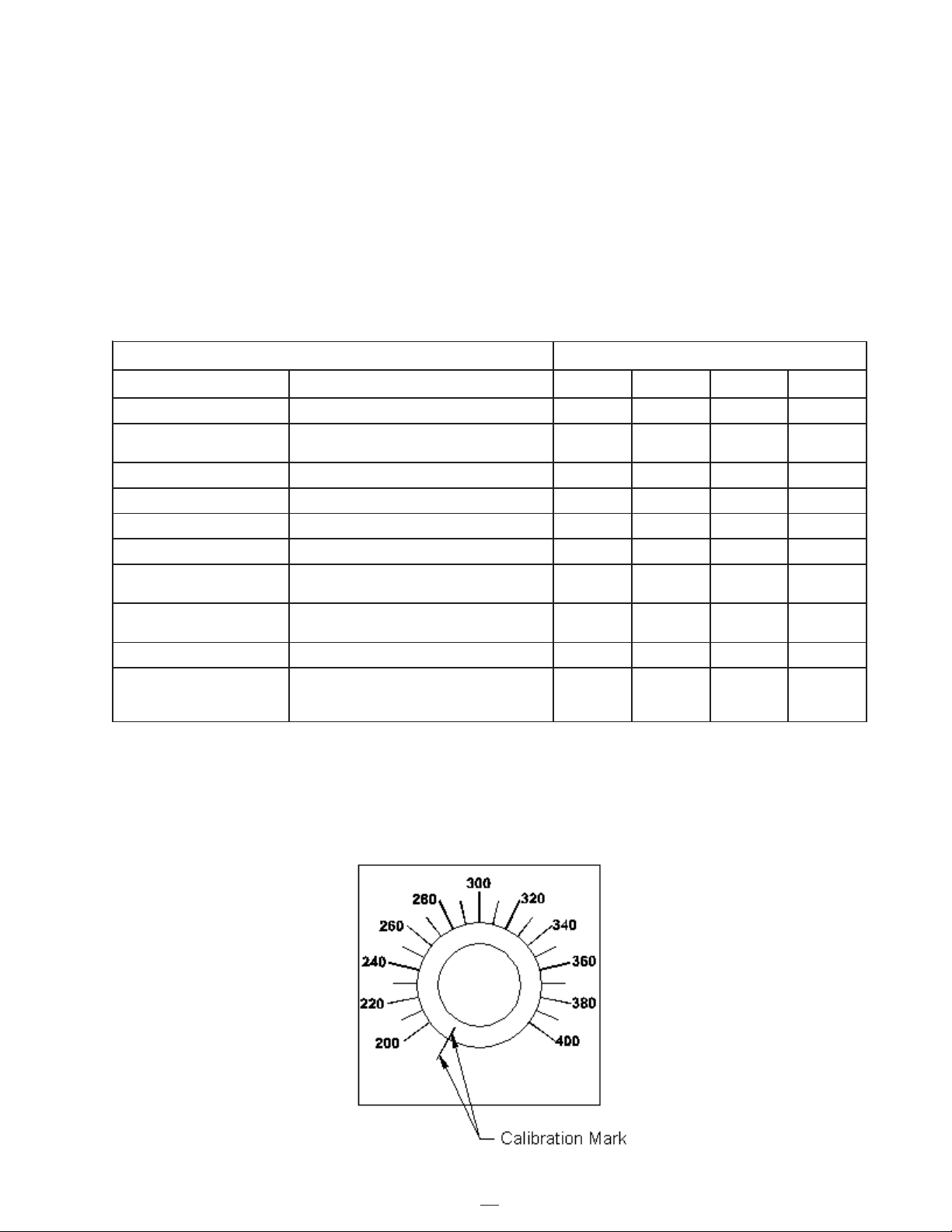
TEMPERATURE CONTROL CALIBRATION
Check control knob calibration weekly. Calibrate by aligning the line on the control knob
with the calibration line on the scale plate (see Fig. 1).
Fig. 1
SRUOH
NOITACOL ERUDECORP 8 05 052 005
levelliokcehcenignE .launamnoitcurtsnienigneeeS *
enignerehtO
ecnanetniam
dnagnitarepoenigneeeS
.snoitcurtsniecnanetniam
yrettaB .ylkeewlevelretawkcehC *
retlifliociluardyH .retliflioegnahC *
liociluardyH .liokcehC *
liociluardyH .lioegnahC *
liociluardyH dednemmocerees,lioreporproF
.stnacirbul&sdiulf
noisnettleB noisnetnokcals"2/1otnethgiT
tlebfoedis *
kcehceriW skaerbrostucrofkcehC *
noitcepsniesoH
cirtcelednaciluardyh
esoh
snoisarbadnastucrofkcehC *

18
SERVICE INSTRUCTIONS
1. Conduct a general inspection of your machine at least once a week. Replace all
worn or damaged parts, make any necessary adjustments and tighten all loose nuts
or screws.
2. Keep regular replacement items in stock for emergency repairs, to avoid costly
“down” time.
3. Watch for leaks. Tighten fitting or repair as necessary.
4. Clean machine externally periodically. Check with sealant manufacturer for
recommendation.
5. Follow recommended maintenance procedures on maintenance chart.
RECOMMENDED FLUIDS AND LUBRICANTS
NOITACILPPA DEDNEMMOCER TNIOPLLUF
lioenignE .launamsrenworelhoKotrefeR .stP4
GPL enaporP .sbL001
liociluardyH ocaxeT86-DH-liOodnoR .slaG21

19
HOSE TROUBLE SHOOTING
HOSE DOES NOT HEAT
Step 1: Is the “HEATED HOSE” switch “ON”?
YES: Go to step 2
NO: Turn switch “ON”.
Step 2: Is “HEATED HOSE” light illuminated?
YES: Go to step 3
NO: Check for tripped circuit breaker in front panel.
YES: Reset circuit breaker.
NO: Remove front panel and check for 12 volts at purple wire on
hose switch.
YES: Go to step 2a.
NO: Check for 12 volts at circuit breaker in front panel.
Step 2a: Check for 12 volts at #3 terminal (purple wire) on Pak-Stat.
YES: Go to step 2b.
NO: Check wire connections or replace switch.
Step 2b: Check for 12 volts at #7 terminal (blue wire) when Pak-Stat is on.
YES: Go to step 3
NO: Replace Pak-Stat.
YES: Check wire connections (red wire) between circuit breaker and switch
NO: Check wire connections between “ACC” teminal on ignition switch
and “A” terminal on plug #2.
Step 3: Check for 12 volts at “BATT” terminal on generator.
YES: Go to step 4
NO: Check wire connections between (blue wire) in control box to
“BATT” terminal on generator.

20
HOSE TROUBLE SHOOTING
Step 4: Check for 24 volts AC at the “BLACK”, “WHITE” and “GREEN” wires on the
generator.
YES: Go to step 5.
NO: Replace generator.
Step 5: Check for 1.08K (1080) OHMS resistance of the hose sensor (black and
white wire) at the junction box. (NOTE: One of the sensor wires must be
disconnected to check resistance).
MATERIAL DOES NOT DISPENSE WHEN PUMP IS ACTIVATED
Step 1: Is the pump cylinder extending?
YES: Go to step 2.
NO: Has the sealant had sufficient time to completely melt.
YES: Go to step 2.
NO: Allow material to heat longer.
Step 2: Has the hose had sufficient time to reach operating temperature?
YES: Go to step 3.
NO: Allow hose to heat longer.
Step 3: Check for continuity inside the control box on the red cube timer at
purple 2 and purple 4 when the wand trigger is pulled.
YES: Go to step 4.
NO: Check for continuity inside the junction box green trigger wire and red
trigger when the wand trigger is pulled wire coming from the control box.
YES: Check for damged wires between the juction box and control box.
NO: Check for continuity inside the junction box between the (2) red
trigger wires from the hose when the wand trigger is pulled.
YES: Replace terminal strip.
NO: Disconnect the hose and wand five pin plug. Check for continuity
on the wand plug between “C” and “B” pins when the wand trigger
is pulled.
YES: Your hose needs to be repaired, Contact Crafco, Inc.
NO: Your wand needs to be repaired, Contact Crafco, Inc.
Step 4: Is the top left light on the hydraulic valve illuminated when trigger is
activated?
YES: Replace coil
NO: Is the shutdown toggle switch in the “ON” position?
Yes: Turn the toggle switch to the opposited position.
No: Go to step 5.
Step 5: Is there 12 VDC between the #9 relay terminal and #12 relay terminal
in the control box when the trigger is pulled?
YES: Check the wiring between the control box and the hydraulic valve.
NO: Go to Step 6.
Table of contents


