Ernex Norsaw 805 User manual

2
CONTENTS
Side
1. Safety instructions 3
2. General instructions/Dust and Noise 4
3. Power supply/Assembly 5
4. Functions/Transport 9
5. Operation 10
6. Maintenance/Repair 11
7. Troubleshooting 12
8. Warranty 13
9. Technical data 14
10. Standard-/Optional equipment 14
11. Illustrations 15
12. Wiring Diagram 18
13. Spare part list/Drawings 20
14. Conformity Declaration 27
15. Product marks 28
Original Manual: Norwegian 545904.

3
1. SAFETY INSTRUCTIONS.
1. This machine is designed and constructed by Ernex AS and has been submitted for test and
found in conformity with the Machine Directive 2006/42/EF, 2006/95/EF and EN 1870-5: 2002.
2. The Health and Safety at Work etc. Act 1974 places duties on designers, manufacturers and
suppliers to ensure that among other things:
1. articles supplied for use at work are, so far as is reasonably practicable, safe and without
risks to health during setting, cleaning and maintenance and 2. persons supplied with the
articles are provided with adequate information about the use for which they are designed and
about conditions necessary to ensure that they will be safe and without risks to health.
3. These duties will apply to you if you re-supply the machine by way of sale, lease, hire or hire
purchase.
4. Persons who install this machine for use at work have a duty under the Health and Safety
at Work etc. Act 1974 to ensure, so far as is reasonably practicable, that nothing about the
way in which it is installed makes it unsafe or a risk to health at all times during setting, use,
cleaning and maintenance. This includes such aspects as correct assembly, electrical instal-
lation, construction of enclosures, fitting of guards and exhaust ventilating equipment. When
installing this machine, consideration must be given to the provision of adequate lighting and
working space.
5. This machine is supplied complete with all necessary safeguards to enable the user to comply
with the Woodworking Machines Regulations 1974 and the Provision and use of Work Equip-
ment Regulations 1992. Details of correct installation and use, together with guidance on fitting
and proper adjustment of guards are described in this manual.
6. The Woodworking Machines Regulations place absolute legal duty on employers and
employees to ensure that guards and the Provision and use of Work Equipment Regula-
tions 1992 and any other safety devices are securely fitted, correctly adjusted and properly
maintained.
7. Repairs and maintenance must only be undertaken by competent technicians. Ensure that
all power supplies are isolated before maintenance work commences. Instructions for routine
maintenance are included in this manual.
8. Machine operators must have received sufficient training and instructions as to the dangers
arising in connection with the machine, the precautions to be observed and the requirements
of the Woodworking Machines Regulations which apply, except where they work under the ade-
quate supervision of a person who has a thorough knowledge and experience of the machine
and the required safeguards.
9. Persons under the age of eighteen years must have successfully completed an approved HSE
course of training before operating this machine at work, unless participating in a course of
training under adequate supervision. (NB. This paragraph is only relevant to: circular sawing
machines, any sawing machine fitted with a circular blade, any planing machine for surfacing
which is not mechanically fed or any vertical spindle moulding machine).
The saw can be used for sawing wood, plywood and chipboard.
The saw must not be used on plasterboard, polystyrene and tarred paper (for roofing).
WARNING: Safety equipment such as riving knife, blade guard and push sticks must not be
removed, but have to be used!
E
NG
L
I
S
H

4
2. GENERAL INSTRUCTIONS/DUST AND NOISE
2.1 General safety precautions
• IMPORTANT! According to the CE-regulations, adjustable rollertable must always be used.
• Ensurethatthereisadequateroomaroundthesaw.
• Forbeststability,placesawonalevelandevensurface.
• Keepsawtable,sawbladecoverandareaaroundsawfreeforoffcutsandexcessive
sawdust.
• Theworkingareashouldbewellventilatedandasawdustextractororcollectormustbe
used.
• Usegoodlightingandadequatehearingandeyesightprotection.
• Whensawinglongerpiecesusetheextrafeedoffrollertableorsuitablesupport.
• Alwayslowertopguardwhensawing.
• Usepushstickswhenrippingsmallstockandwhenthedistancebetweensawbladeand
rip fence is less than 120 mm (approx. 5").
• Alwaysswitchmotoroffwhenadjustingbladeorturntableangle.
• Lowersawbladewhennotinuse.
• Alwaysuserivingknife.Seesection6.2foradjusting.
• Disconnectmaincablewhenchangingsawbladeorperformingothermaintenancework.
• Useonlycarbide-tippedsawbladewhichisproperlysharpened.Neveruseacrackedor
deformed saw blade.
• Ensurethatthesawbladecoverplateisclosedaftersawbladehasbeencleanedand/or
changed or if riving knife has been changed or adjusted.
• Wornaluminiumedgingstripsinturntableshouldbereplaced.
Dust and Noise
Dust and noise measurements have been performed for work with the materials and saw-
blades for which the machine is intended (see Section 1 Safety Instructions).
Measurement uncertainty is related to local conditions and can vary with the saw blade/trans-
mission characteristics. Follow the maintenance instructions (see Section 6 Maintenance/
Repair
Ear protection must be used, and a dust mask is recommended
For indoor use, the machine must be connected to an extractor that provides a minimum air
speed of 30 m/s i.e. 1.8 kPa.

5
3. POWER SUPPLY/ASSEMBLY
3.1 Mains connection
• Saws are supplied with standard plugs (only in the U.K.). Any extension cord being
used should be a cable with a conductor cross-section of 2.5 mm2.
• NOTE!Extensioncordsmusthavegroundprotection.
3.2 Connecting mains supply - direction of rotation
• Whenconnectingmainstoasawwithathree-phasemotor,checktoseethatthesaw
blade rotates in the right direction (away from the riving knife). The direction of blade
rotation is indicated on the blade housing under the table. If the blade rotates in the wrong
direction, two of the phases must be switched. This should be done by an electrician.
Check also to see that blade is mounted correctly with regards to direction of rotation.
3.3 Assembly
• Attachthesawtothebaseusingthetwomountinghooks(Fig.9).
• Checktherivingkniferegularlytoensurethatitispositionedcorrectly(Fig.1).
• Mountthehandletotheelevationarm(Fig.2).
• Screwtheturntablelockinghandleintothenutbelowthetableandsecurewiththelock-
nut (Fig. 3).
• LoosenthescrewsandpositionthetopguardasshowninFig.4and5.Tightenthe
screws firmly.
The drawings may vary from the present model.
N.B! - These drawings can be found on page 15-18.
S2 T3
R1 N
3P+N+
Kobl. 400V (5 pins)
E
NG
L
I
S
H

6
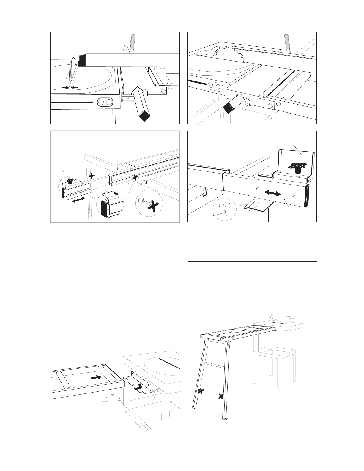
3.4 Assembling the adjustable infeed table
• Fastenthebracketstothesawguiderail.Screwinallscrewsloosely.(Fig.1)
• Fastentheguiderailtothebrackets.
• UnscrewthestopscrewB(Fig. 2).
• Ensurethatthejawsofclamp C are open, and push the roller unit D into the guide rail;
tighten stop screw B.
• Normally,itisnotnecessarytoadjusttheballbearingsontherollerunitbut,ifnecessary,
loosen the ball-bearing screws just below the unit, and adjust with screws E, so that the
roller unit runs easily without wobbling. After adjustment, tighten the locknuts and the ball-
bearing screws.
• PulltherollerunittowardsstopscrewB. Adjust the distance between the saw table and the
roller unit to about 15 mm.
• UsethesupporttrestleL(Fig. 4) when assembling the infeed table F(Fig. 2). Affix the
infeed table to the roller unit using screws and nuts G (do not screw too tightly).
• AdjustthescrewsH so that the roller unit and infeed table are in the same plane. Check
using the rip fence. Tighten the locknuts.
• UsingscrewsA(Fig.1), adjust the height of the roller unit so that it lies in plane with the
turntable on the saw.
3.5 Assembling the rip fence
• AfxthefasteningbracketCand the locking handle to the infeed table using nut E(Fig. 3).
• LowerthetrestleL(Fig. 4), and push the fence into position. Raise the trestle.
• Rotatetheturntableto0°.Usingasetsquare,adjusttheguiderailsothatthefenceisata
90°angletothesawblade(Fig.5).
• Fastenthefencesothattheend-pieceofthefenceis3mmfromthesawbladeandthe
scale displays the correct value (Fig. 6).
• Rotatetheturntableto90°,andpullthefenceintowardthesawblade.Adjusttheindicator
P so that it points to 0 on the guide rail (Fig. 7).
• AdjustthelegsofthetrestleL (Fig. 4) so that both ball bearings rest against the trestle.
3.6 Assembling the telescopic extension
• Removetheendstopfromtheripfenceandpushthetelescopicextension R into the fence.
Put the end stop in the telescopic extension (Fig. 9).
• AttachthelockingscrewQto the telescopic extension (Fig. 8).
• AttachthebracketSto the telescopic extension (Fig. 9).
3.7 Assembling the length stop
• MountthelengthstopT edge-to-edge with the aluminium end of the telescopic extension
(Figs. 8 and 9).
3.8 Assembling the fixed table
• AssembleasillustratedinFigs.10and11.

7
C
E
Montering av regulerbart rullebord
Mounting of adjustable table
Montage des Schieberollentischs
M10x16
M8x16
M8x16
G
M6x45
G
M8x35
B
M8x16
F
C
D
H
E
A
Fig. 1
Fig. 2
Fig. 3
Fig. 4 Fig. 5
L
8
M8x30
Montering av fast Rullebord
Mounting of fixed table
Montage des festen Rollentischs
M8
3mm
P
T
Q
T
M8x16
SR
Fig. 6
Fig. 8
Fig. 7
Fig. 9
Fig. 10 Fig. 11
9
4. FUNCTIONS/TRANSPORT
4.1 On/Off switch
A green ON button and a red OFF button are located on the saw’s front panel (Fig. 6). The ON button
is equipped with a lockable cover. The saw is provided with a low-voltage cutout as well as overload
protection which disconnects the power supply under overload conditions to prevent motor damage.
If this occurs, let the motor cool down for a few minutes, after which it will be ready to run again. Try
to avoid overloading motor.
4.2 Raising and lowering saw blade
Free the elevation arm by loosening the elevation locking clamp (Fig. 7), whereupon the blade may
now be raised and lowered. The saw blade may be locked into position at any height by retigh-
tening the locking clamp.
4.3 Tilting the saw blade
The saw blade must be in low position before adjusting bevel angle. This adjustment is made by
loosening the tilt locking clamp and pressing the tilt preset. The saw blade may now be tilted to any
bevelanglebetween0°and45°(Fig.8),withtheangleindicatedonthecurvedscale.Tightenthe
tilt locking clamp when finished.
4.4 Turning turntable
Theturntablemayberotatedhorizontallyineitherdirectionandsetatanycutoffangle.Loosenthe
turntable by pushing locking handle to the left (Fig. 9). Turn the turntable to the desired cutoff angle
bymeansoftheelevationarm(scaleontabletopindicatescutoffangle).Locktheturntablebypush-
ingthelockinghandletotheright.Frequentlyusedangles(90°,45°,30°,22,5°,15°and0°)are
preset.
IMPORTANT! To prevent personal injury or damage to saw, the motor must be shut off while
making any saw blade adjustments.
When lifting using a crane, attachment straps can be placed around the legs. Wheels can be
supplied as an option.

10
5. OPERATION
5.1 Crosscuts
• Setcuttinganglesasdescribedinsection4.4(or4.3ifapplicable).
• MovelongfenceinclosetosawbladeslotandlockwithfencelockingclampJ(Fig. 10).
• AdjusttopguardUheight to about 5 mm (3/8") above thickness of workpiece, and lock
with top guard locking clamp V(Fig. 10).
5.2 Ripping
• Rotateturntabletothe90° mark, setting it parallel with the long fence (Fig. 9,11 and 12),
and lock as described in section 4.4.
• Adjustbevelangleifdesired,asdescribedinsection4.3(Fig.8and13).
• Raisesawbladetoslightlyhigherthanthicknessofworkpieceandlockasdescribedin
section 4.2 (Fig. 7).
• Setlongfencetothedesiredrippingwidth,andlockwithrollertablelockingclampsCon
Fig. 14 and 15.
• LoosentopguardlockingclampV, allowing the leading edge of the top guard to rest on
the table top (Fig. 11). This will permit the workpiece to lift the top guard and slide under-
neath as it is fed into the saw.
• Startthemotorandpushtheworkpiecealongthelongfenceandintothesawblade
(Fig.11 and 12).
IMPORTANT! Always use riving knife. Make sure that it is positioned correctly and that it is of the
correct thickness. See section 6.2.
Feed the workpiece at an even rate, reducing the pressure if the motor starts working hard (this will
be quite noticeable). This protects the motor and yields a cleaner cut.
5.3 Angled crosscuts
• Setturntabletodesiredangle(Fig.16).
• Adjustlongfenceandcarryoutcuttingoperationasdescribedinsection5.1.
5.4 Bevelledandangledcrosscuts
• Setturntabletodesiredcutoffangle.
• Tiltandlocksawbladeindesiredbevelangle.
• Adjustlongfenceappropriately(Fig.17).
5.5 Cuttingtongueandgroove
• Rotateturntabletothe90°mark,settingthesawbladeparallelwiththelongfence,andlock
as described in section 4.4.
• Adjustsawbladeheight(depthofgroove).
• Setfeedtabletodesiredpositionandlock.
• Feedtheworkpiecealongthelongfence.
• Forawidergroove,movefeedtableslightlyoffsetandrepeatthelaststep(Fig.18).

11
E
NG
L
I
S
H
6. MAINTENANCE/REPAIR
IMPORTANT! Make sure power supply is disconnected while performing maintenance
operations. A minimum of maintenance is required to ensure satisfactory performance and
a long service life.
• Lubricatemovingparts,linkagesandthebearingscarryingtheturntableatregularinter-
vals.
• Checkallscrewsandnutsregularlyfortightness.
• Keepsawandsawbladehousingfreefromsawdust.Payparticularattentiontomotor
ventilation openings and cooling ribs.
• Keepsawbladecleanandinorder.Replacebladeifthereareanycracksormissingteeth.
Remove resin deposits with a suitable cleaning fluid.
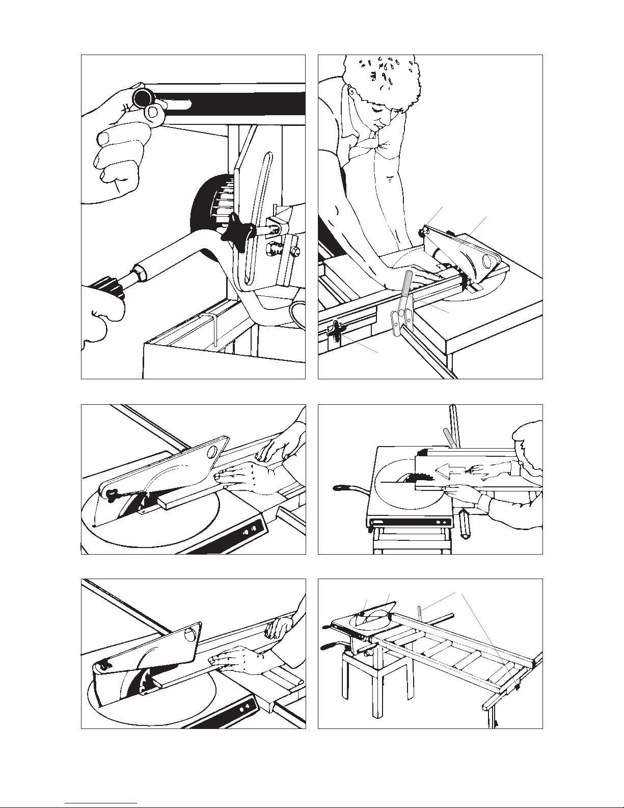
6.1 Replacing saw blade
• Disconnectplug.
• Lowersawbladecompletely.
• RaiseplateBand open cover by removing screws Ain front (Fig. 19).
• Immobilizearborbyinsertingascrewdriverthroughtheholeinthearborandcover,and
loosen arbor screw with an 17 mm (11/16") wrench (Fig. 20). Remove washer and saw
blade. NOTE! Arbor screw has left-hand thread.
• Replacesawbladeinreverseorder.Rememberdirectionofrotation.
6.2 Replacing/adjustingrivingknife
• Pulloutplugandopencoverasdescribedinsection5.1.
• Loosenattachmentscrew(Fig.21)andliftoutrivingknife(forreplacingknife).
• Replacerivingknifeinreverseorderofremoval.Alwaysuseaknifethatis0.2mm(0.008")
thicker than sawblade base.
• PositionrivingknifeasillustratedinFig.1,andtightenattachmentscrew.
6.3 Replacingdrivebelt
• Pulloutplugandremovesawbladeandrivingknifeasdescribedinsections6.1and6.2.
• Removecoverbyremovingthefourattachmentscrewswiththemotorandsawbladerst
raised and than lowered (Fig. 22).
• Workbeltoffpulleysusingascrewdriver(Fig.23).
• Replacebeltinreverseorder.
6.4 Turntable clamp adjustment
• Loosenclamp,Fig.24.
• LoosenlocknutP.
• ScrewslottedscrewOin or out as necessary until turntable clamp locks firmly when
handle is in locked position.

12
REPAIR
Routines at repair:
*The machine must only be repaired by qualified electricians or authorised service
workshops.
Testingthebrakes:
*The brake for the saw blade rotation should be tested regularly. The stop-time must be
max. 10 sec. Start/stop the saw 10 times in a row and check the stop-time.
7. TROUBLESHOOTING
The saw does not start:
* check the power supply
* do not use the cable with several machines at the same time
* check that the cable is not too long, and that the cross-section is not too small
* contact an electrician
Thesawvibratesandisweak:
* check that the blade box below the saw table does not contain chips and sawdust
* check that the toothed belt is undamaged
* check the spindle
* check the blade for eccentricity, and that all the teeth are whole and sharp
Thesawbladeisheavytoliftanddoesnotgodowncompletely:
* check that nothing is stuck in the blade box

13
8. WARRANTY SERVICE
Notwithstanding any statutory requirements, Ernex AS provide warranty in accordance with the
legislation of the customer‘s own country of residence, but in all cases for a minimum of 3 years,
except for electrical parts which still has a 1-year warranty commencing from the date on which the
machine is sold to the end user. Ernex AS/The importer promise to repair, or at our option, replace
with like grade and quality any product determined to be faulty due to the failure of parts, material
or workmanship.
The warranty covers defects in material and/or workmanship only. When making a claim under the
warranty, proof of purchase bearing the original date of purchase must be submitted. The repairs
under warranty may only be carried out by Ernex AS, or by authorized Ernex warranty service
agents or the importer.
The warranty will not apply in cases of:
- incorrect use, overloading of the machine or fitting non-approved accessories
- use of force, damage caused by external influences, or foreign bodies
- damage caused by non-observance of the instructions for use, such as connection to an
unsuitable mains supply or voltage or non-compliance with the installation instructions
- normal wear and tear
The warranty also does not cover machines which have been partially or completely dismantled.

14
9. TECHNICAL DATA
Norsaw 805
Manufacturer: Ernex AS, Norway.
Model: Norsaw 805.
Table: 440 mm x 530 mm.
Height w/o base: 440 mm.
Height w/base: 850 mm.
Transp. height: 560 mm.
Weight: 48 kg.
Sawblade: Carbide-tipped, Z=30.
Diam. 204 mm.
Arborhole30mm.(USA31.75mm)
Kerfwidth2,8mm.
Blade thickness 1,8 mm.
Riving knife: Hardened steel, standard thickness 2,2 mm.
Cuttingheight: 70mmat90°(vertical).
48mmat45°(tilted).
Motor: 1.1 kW 110 V/50 Hz single-phase.
1.1 kW 230 V/50 Hz single-phase.
1.1 kW 400 V/50 Hz three-phase.
1.0 kW 120 V/60 Hz single-phase.
Motorspeed: 2800rpm.(USA3360rpm)
Spindlespeed: 3600rpm.(USA4320rpm)
Peripheral speed: 38.5 m/s with standard blade.
Cable dimension: Single phase 3 x 1.5 mm2.
Three phase 5 x 1.5 mm2.
Fuse: 10A time-lag fuse (230V), 16 A (110 V/120 V).
Switch: On/Off with overload and low-voltage cutout.
Drivebelt: Single toothed belt.
Noise as per
DIN 45635: No-load: 79,0 dB.
Loaded:84,0dB.
-certification: Certified by Dansk Teknologisk Institut,
Aarhus. Identification number: 0396,
approval certificate number TI-09-MD-0309.
10. STANDARD EQUIPMENT
• Base
• Carbide-tippedblade
• Pushsticks
OPTIONAL EQUIPMENT
• Infeedtablewithfenceandlengthstop*
• Fixedtable
• Wheels
• Telescopicextension
• Sawdustextractor.
* In accordance with CE-regulations the adjustable infeed rollertable must always be used.

15
E
NG
L
I
S
H
Fig. 6
Fig. 1 Fig. 2
Fig. 3 Fig. 4
Fig. 5
Fig. 7 Fig. 8
Max
2 mm
Min 3 mm
Max 8 mm
16
Fig. 9 Fig. 10
Fig. 11 Fig. 12
Fig. 13 Fig. 14
J
VU
C
VUC

17
Fig. 17 Fig. 18
Fig. 19 Fig. 20
Fig. 21 Fig. 22
Fig. 16Fig. 15
C
AA
B

18
Fig. 23
ELEKTRISKKOPLINGSSKJEMA
Fig. 24
P
O
02
1
0
43
44
33
34
23
24
13
14
a
b
L
N
PE
ws
br b1 gn/ge
01 GehaeuseK570.
02 Schuetz E3250.
230V 1-fas
01
sw
sw
sw
805 - 230V/1
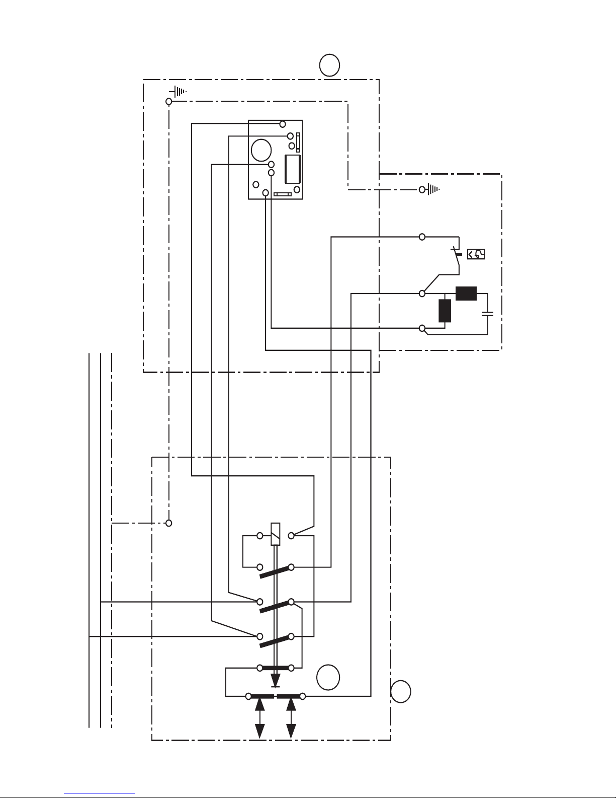
19
01
04
1
041
42
33
34
23
24
13
14
a
b
L
N
PE
03
05
ws br b1
gnge
01 Kleinschuetz E3250 3s-1oe mit Vorschaltoeffner.
03 Bremsplatine Nr. 408200.
04 Gehaeuse K500.
05 Gehaeuse K700
110V 1-fhasig

20
gng
e
01
04
1
0
41
42
33
34
23
24
13
14
a
b
L3
N
PE
03
0
5
br sw b1
0
1 Kleinschuetz E3250 3s-1oe mit Vorschaltoeffner.
0
3 Bremsplatine Nr. 408200.
0
4 Gehaeuse K500.
0
5 Gehaeuse K700
400
V Drehstrom
L2
L
1
Table of contents


