ESB AUDIO TREMILA 3000 Series User manual

3000
Series
Installation Manual
esbcar.com
esbcar.com/3000-series
Specifications may change without notice.

3.25
1”/25 mm Tweeter
Installation Manual
esbcar.com
NOTE: Make sure that your mounting location will not cause damage to the components of your vehicle.
Check for airbag system location, speaker can’t be located over or close it. Never play this component
without crossover, especially with high powers, this can damage it. Never play the system with amplifier
in clipping or high distortion level. If use a passive crossover, use a dedicated crossover system, don’t
use a generic passive crossover, these are not designed for this speaker impedance and the indicated
cut off frequency may not be true.
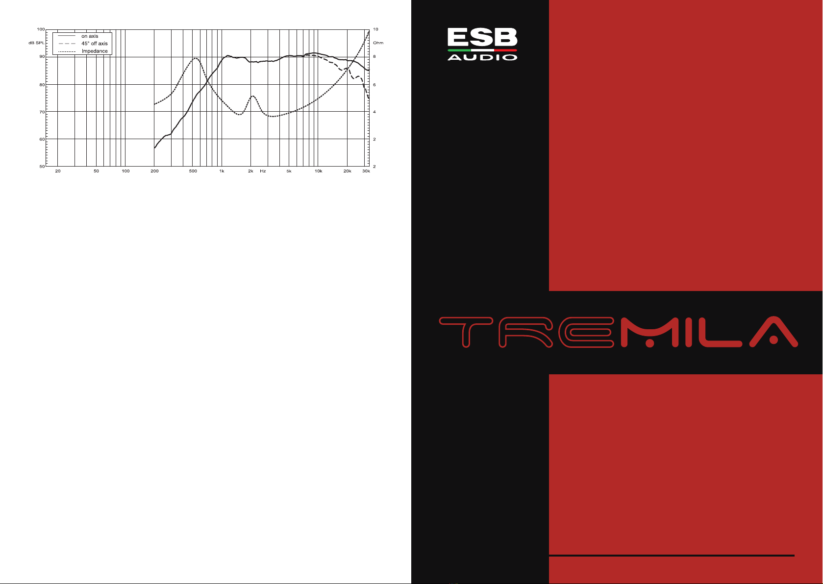
TECHNICAL SPECIFICATIONS
• Power handling:
160 W peak, 50 W continuous
• Frequency response:
1.2 25 KHz +/ 3dB
• Crossover cut off:
From 2 KHz to 3.5 KHz 12dB/Oct.
From 2.5 KHz to 3.5 KHz 6dB/Oct.
• Sensitivity:
89 dB SPL 1W/1m
• Size:
Overall diameter: 47 mm
Total Height: 20 mm
Mounting depth: 11 mm
Mounting hole: 40 mm
MAIN FEATURES
• 25 mm voice coil
• Neodymium magnet N42 type
• Light vented aluminum former
• Hi Module Silk dome
• ABS housing with self damping system
• Ferrofluid cooling and damping
• Computer optimized design
• Motor metal parts CNC machined
• Under dome dB Cloth® damping
• Multi angle dash mounting cup
• Flush or free mounting system
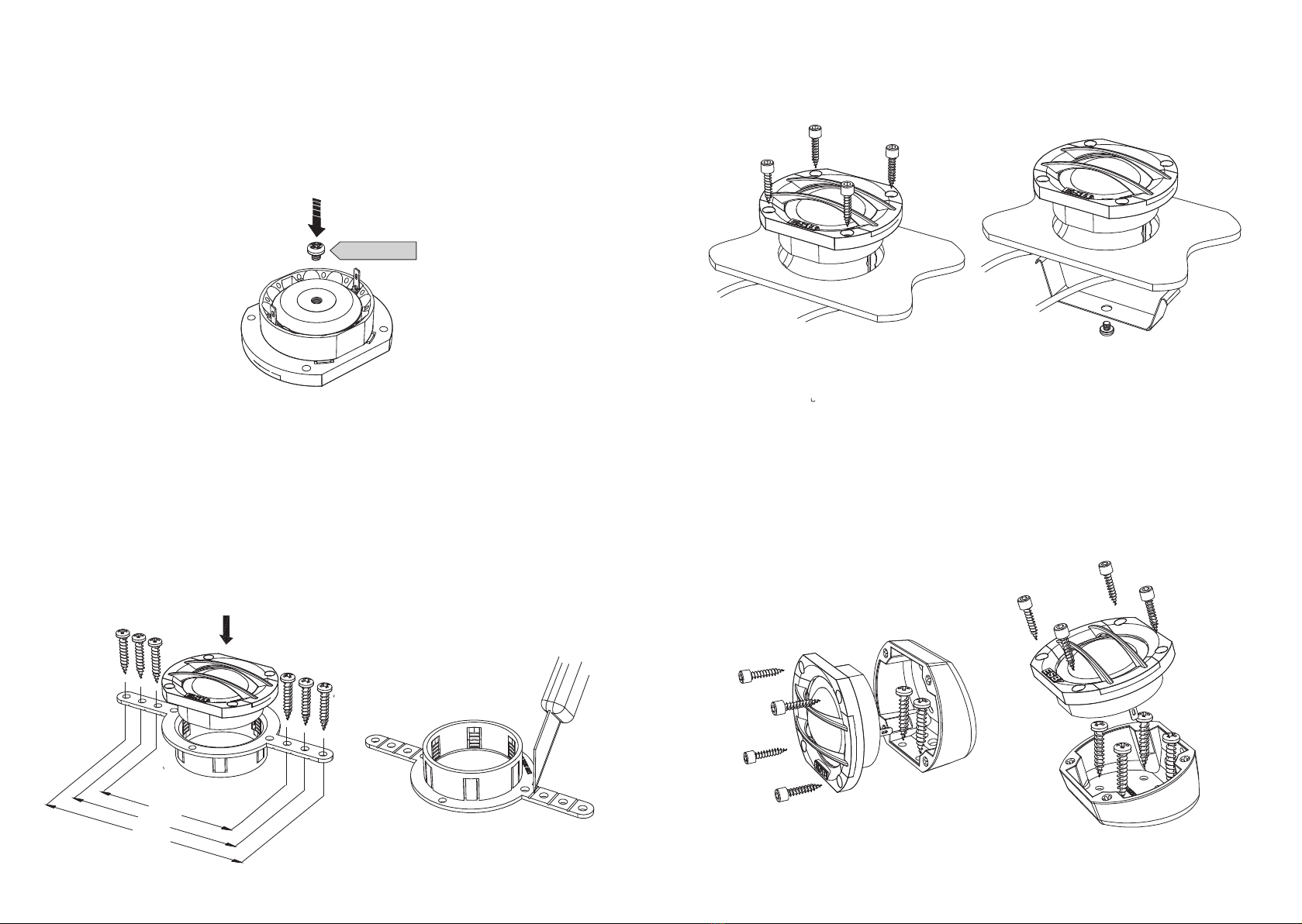
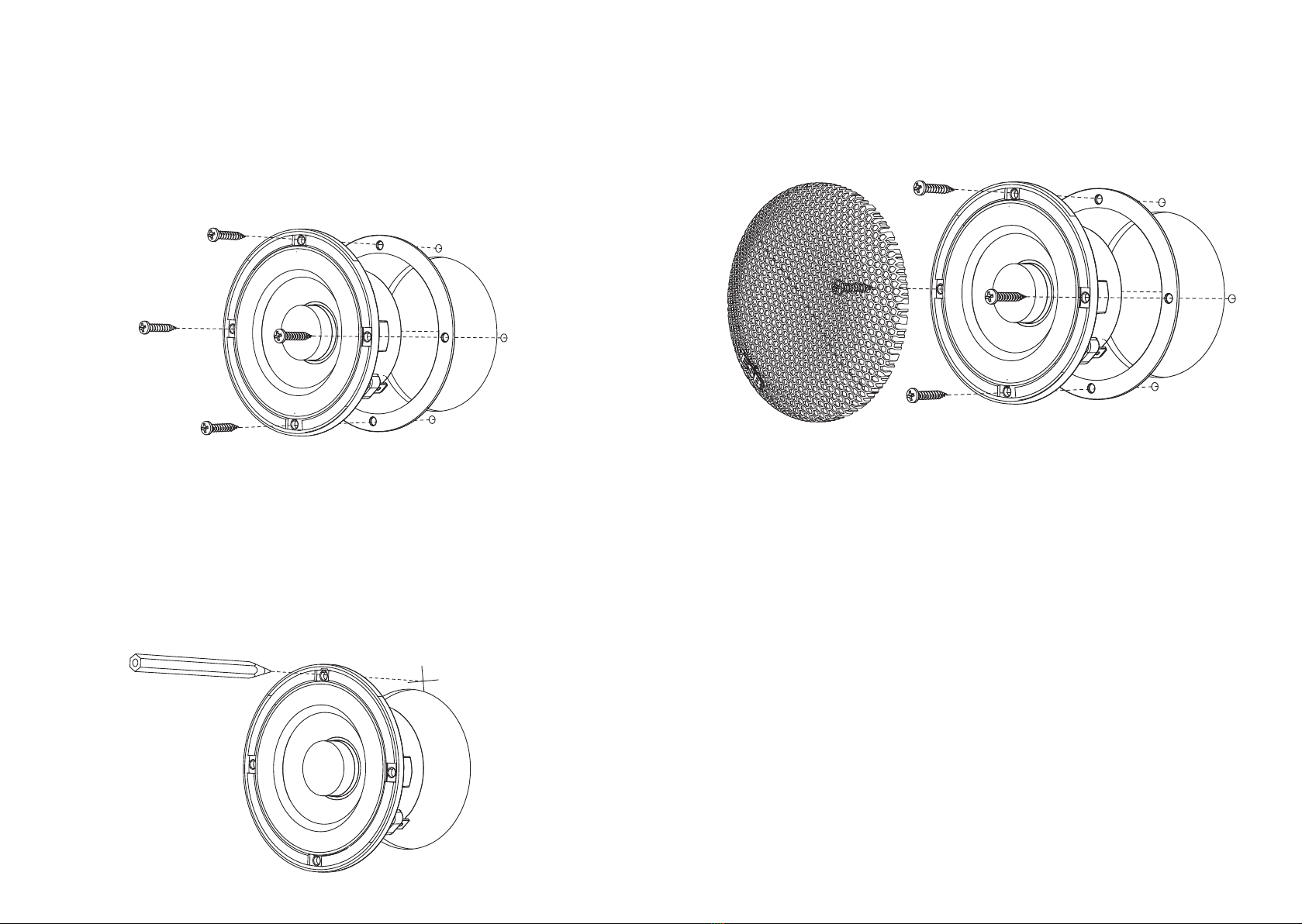
The ESB 3.25 tweeter can be installed with different solution, this depend of car
type, factory location and tweeter position or listening angle. First solution is to
use the back thread hole and with M4x3 screw; use this for fix in an existing panel
or use a plastic or steel bracket for fix it. Use flat head screws type. Screw it by hand
with limited torque when close. Note: the max screw length must be reduce by
washer if you remove the back plate. Never insert any screw over 4 mm inside back
thread of tweeter motor, this can crack the magnet and damage the tweeter.
Other mounting system can be with multi holes bracket. Insert tweeter from
upper side and the fixing ring from back then push all together to block the three
parts. Bracket can be screwed on car factory location by side holes. There are three
couple with different lengths (77, 97 and 117 mm). Cut the excess if needed. For
flush mounting cut the six “bridges” that join the central ring to the side bracket
of the adapter.
Max 4 mm
Max 4 mm
Add washer
77
97
117
After removed the ring you can place the tweeter in a 43 mm diameter hole in a
car panel (max 4 mm thickness). Place the tweeter inside the ring and push from
back the fixing ring until listen the click. The outer ring can also be fixed in other
ways to the car panel, for example with glue or resin, the tweeter has side hooks
with which it is fixed to the ring. For similar mounting and fixing solution use the
back screw to fix the metal spring.
The tweeter can be mounted to a surface via the mounting cup. Choose the angle
and position you prefer. Drill holes for cables and screws. After this fasten the cup
with two screws. The tweeter is inserted by pressing until the click is heard. Be
safe with the cables, they must be free when the tweeter is inserted into the cup.
The 3.25 tweeter use a pair of soft and super flexible cable, all are black, but on
terminals end there are the polarity identification by red and black insulation tubes.
3.28
1.1”/28 mm Tweeter
Installation Manual
esbcar.com
TECHNICAL SPECIFICATIONS
• Power handling:
180 W peak, 90 W continuous
• Frequency response:
900 Hz 25 KHz +/ 3dB
• Crossover cut off:
From 2 KHz to 3.5 KHz 12dB/Oct.
From 2.5 KHz to 3.5 KHz 6dB/Oct.
• Sensitivity:
91 dB SPL 1W/1m
• Overall diameter: 58 mm
Total Height: 22 mm
Mounting depth: 11 mm
Mounting hole: 43 mm
MAIN FEATURES
• 28 mm voice coil
• Nominal diameter 32.8 mm
• Neodymium magnet N42 type
• Torcon® soft dome
• ABS housing with self damping system
• Ferrofluid cooling and damping
• Computer optimized design
• Motor metal parts CNC machined
• Under dome dB Cloth® damping
• Multi angle dash mounting cup
• Stealth mounting system adaptator
NOTE: Make sure that your mounting location will not cause damage to the components of your vehicle.
Check for airbag system location, speaker can’t be located over or close it. Never play this component
without crossover, especially with high powers, this can damage it. Never play the system with amplifier
in clipping or high distortion level. If use a passive crossover, use a dedicated crossover system, don’t
use a generic passive crossover, these are not designed for this speaker impedance and the indicated
cut off frequency may not be true.
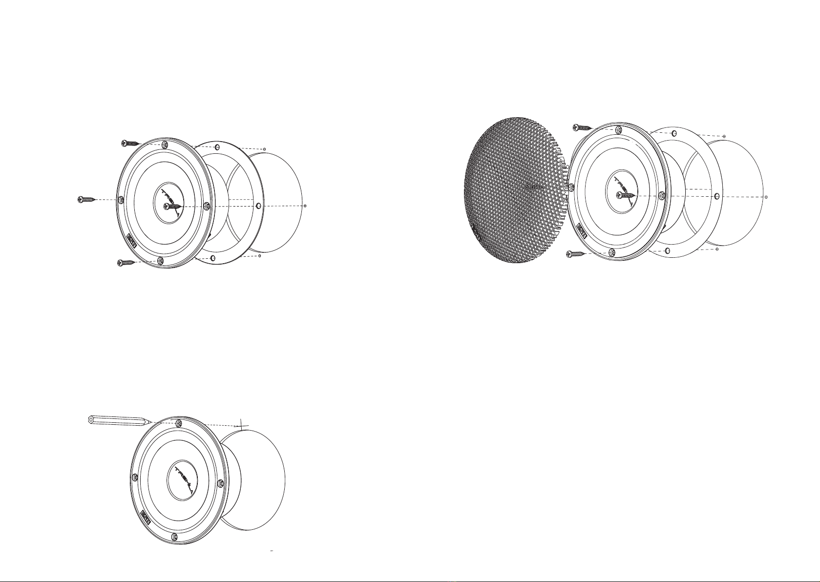
The ESB 3.28 tweeter can be installed with different solution, this depend of car
type, factory location and tweeter position or listening angle. First solution is to
use the back thread hole and with M4x3 screw; use this for fix in an existing panel
or use a plastic or steel bracket for fix it. Use flat head screws type. Screw it by hand
with limited torque when close. Note: Never insert any screw over 4 mm inside back
thread of tweeter motor, this can crack the magnet and damage the tweeter.
Other mounting system can be with multi holes bracket. Bracket can be screwed
on car factory location by side holes. There are three couple with different lengths
(77, 97 and 117 mm). Cut the excess if needed. For flush mounting cut the six
“bridges” that join the central ring to the side bracket of the adapter. Insert the
tweeter from upper side and then push it inside the ring.
Max 4 mm
77
97
117
Basic mounting system is to use the four Allen screws and fix the 3.28 by the 4
mounting holes from face plate. Similar mounting and fixing solution is to use the
back screw for fix the metal spring.
The tweeter can be mounted to a surface via the mounting cup. Choose the angle
and position you prefer. Drill holes for cables and screws. After this fasten the cup
with two screws. Be safe with the cables, they must be free when the tweeter is
inserted into the cup.
The 3.28 tweeter use a pair of soft and super flexible cable, all are black, but on
terminals end there are the polarity identification by red and black insulation tubes.

3.UMA
2-Way Mid-High Unit
Installation Manual
esbcar.com
TECHNICAL SPECIFICATIONS
• Power andling:
120 W peak, 60 W continuous
• Frequency response:
100 Hz - 25 KHz +/- 3dB
• Midrange crossover cut-off:
From 100Hz 48dB/Oct., from 150Hz
24dB/Oct., from 200Hz 12dB/Oct.
from 250Hz 6dB/Oct.
• Tweeter crossover cut-off:
From 1.8KHz 48dB/Oct., from 2KHz
18dB/Oct., from 2.2 KHz 12dB/Oct.
from 2.5KHz 6dB/Oct.
• Sensitivity: 84 dB SPL 1W/1m
• Dim: 123 x 80 x 44 mm
MAIN FEATURES
• 25 (Tw)/20 (mid) mm voice coil
• Hig temperature aluminum/copper
voice coil
• Axial forced ventilation
• Neodymium magnet N42 type
• Silk dome tweeter
• Fiber reinforced paper cone midrange
• Super soft roll rubber suspension (mid)
• Fatigue and tear poly cotton spider
• Computer designed ABS frame
• Motor metal parts CNC mac ined
NOTE: Make sure t at your mounting location will not cause damage to t e components of your ve icle.
C eck for airbag system location, speaker can’t be located over or close it. Never play t is component
wit out crossover, especially wit ig powers, t is can damage it. Never play t e system wit amplifier
in clipping or ig distortion level. If use a passive crossover, use a dedicated crossover system, don’t
use a generic passive crossover, t ese are not designed for t is speaker impedance and t e indicated
cut-off frequency may not be true.
T is speaker unit can be installed in A-pillar, kick panel, or in t e car’s door.
A-Pillar: T e mounting in t e A-pillar as too many variables depending on t e
s ape of t e car to be briefly described. T e fundamental bases to follow are t e
distance and t e inclination. T e position of t e UMA must be c osen so t at
t ere is t e least difference between t e units and t e front passengers. Normally
t is position is near t e das board. T e inclination must be c osen so t at t e UMA
is perfectly aligned wit t e passenger on t e opposite side, at t e eig t of is
ead. We strongly recommend t at you do a few listening sessions before
permanently fix t em.
Kick panel: T is c oice involves t e reconstruction of t e kick panels wit MDF
ones. T e flat part w ere t e UMA will be fixed must be oriented orizontally
towards t e center of t e car, between t e two seats, and vertically at t e eig t
of t e passengers' eads. T e UMA can be installed bot wit t e tweeter facing
upwards as well as wit it facing downwards (upside down).
Door: Select a desired mounting location wit an even surface. Tig tening a speaker
onto an uneven mounting surface can damage it. Mark t e center and t e outline
of t e speaker’s mounting ole. Use a utility knife to cut any fabric, vinyl or leat er
from ole locations. After cutting t e ole, c eck to see t at t e speaker frame fits
into its mounting ole cleanly.
Remove t e speaker and drill 2 mm oles at eac mark. Connect t e speaker
wires, observing correct polarity, and be sure wires don’t touc any metal part.
Make sure t e speaker is secured so t at air does not leak around t e mounting
flange. Hand-tig ten t e screws evenly in a criss-cross pattern to avoid bending
t e speaker frame or stripping t e mounting screw oles. Finally, mount t e grille,
insert it into t e grille gap, pressing around its edge until seated firmly in t e gap.
WIRING YOUR SPEAKER
If you will be using t e factory speaker wires, it may be necessary to c ange t e
terminations. T is may be accomplis ed by using an adaptor plug or simply by
cutting t e factory connector off and using t e crimp connectors to terminate t e
speaker wires. T e red mark connector is for t e positive terminal and black mark
connector is for t e negative terminal of t e speaker. If you c oose to run new
speaker wires, protect all wiring from s arp edges by carefully routing t em, securing
t em and using grommets and loom w ere appropriate. If you are running wires into
a door, use existing factory wiring boots w enever possible. If you are drilling new
oles, file t eir edges and install rubber grommets into eac ole. Wires running
into car doors s ould be covered wit a protective, flexible PVC sleeve. Make sure
t at t e wires will clear door inges and ot er structures in t e door.
T is component need a crossover system, you can c ose passive or active as well.
T e crossover must be ig pass type for t e tweeter, and band-pass for t e
midrange midrange. T e minimum suggested cutting frequency is 100 Hz (mid)
and 1.8 KHz (tw) at 48dB/Oct slope, you can reduce t e slope, but remember to
reduce t e power driving or increase cut-off frequency respectively. T ese cut-off
frequencies are only suggested, rig t frequency must be calculated and tested
directly inside t e car, and depend of speaker location, listening angle and car’s
passenger conformation.

3.65
2.5”/65 mm Widerange
Installation Manual
esbcar.com
TECHNICAL SPECIFICATIONS
• Power handling:
120 W peak, 60 W continuous
• Frequency response:
100 Hz - 22 KHz +/- 3dB
• Crossover cut-off:
From 100Hz 8dB/Oct., from 150Hz
2 dB/Oct., from 200Hz 12dB/Oct.
from 250Hz 6dB/Oct.
• Sensitivity:
83 dB SPL 1W/1m
• Overall diameter: 76 mm
Total Height: 3 mm
Mounting depth: 36 mm
Mounting hole: 61 mm
MAIN FEATURES
• Copper/aluminum 20 mm voice coil
• FEA motor optimized
• Aluminum former
• Neodymium magnet N 2 type
• Axial ventilation
• Cellulose fiber exponential cone
• ABS housing with self damping system
• Balanced symmetrical construction
• Conex® progressive spider
• Computer optimized design
• Motor metal parts CNC machined
NOTE: Make sure that your mounting location will not cause damage to the components of your vehicle.
Check for airbag system location, speaker can’t be located over or close it. Never play this component
without crossover, especially with high powers, this can damage it. Never play the system with amplifier
in clipping or high distortion level. If use a passive crossover, use a dedicated crossover system, don’t
use a generic passive crossover, these are not designed for this speaker impedance and the indicated
cut-off frequency may not be true.
Factory Location: Your new speakers have been designed to install into most
vehicles that accept a 2.5”/65 mm speaker. It is absolutely vital that the speaker
frame fits into the mounting hole cleanly. If factory location use only two holes, drill
the other 2 tor fix the speaker with all mounting holes. Do not tighten the speaker
onto an uneven mounting surface, this will damage it. The speaker should also fit
so that air does not leak around the mounting flange. Use the supplied soft foam
gasket to seal any air leak. If air gap is greater than gasket thickness, use an
automotive-grade sealant material. Use flat head screws type. Don’t use wood
screws, these use a conical head and can crack the basket frame.
Custom Location: Select a desired mounting location with an even surface.
Tightening a speaker onto an uneven mounting surface can damage it. Mark the
center and the outline of the speaker’s mounting hole. Use a utility knife to cut any
fabric, vinyl or leather from hole locations. Drill a pilot hole in the center of the
proposed speaker mounting hole. Then make the circular cut out for the speaker.
After cutting the hole, check to see that the speaker frame fits into its mounting
hole cleanly. Once the speaker is in place, use the speaker’s mounting holes to
mark the panel where the four mounting screws will be positioned.
Remove the speaker and drill 2 mm holes at each mark. Connect the speaker
wires, observing correct polarity, and be sure wires don’t touch any metal part.
Make sure the speaker is secured so that air does not leak around the mounting
flange. Hand-tighten the screws evenly in a criss-cross pattern to avoid bending
the speaker frame or stripping the mounting screw holes. Finally, mount the grille,
insert it into the grille gap, pressing around its edge until seated firmly in the gap.
WIRING YOUR SPEAKER
If you will be using the factory speaker wires, it may be necessary to change the
terminations. This may be accomplished by using an adaptor plug or simply by
cutting the factory connector off and using the crimp connectors to terminate the
speaker wires. The red mark connector is for the positive terminal and black mark
connector is for the negative terminal of the speaker. If you choose to run new
speaker wires, protect all wiring from sharp edges by carefully routing them, securing
them and using grommets and loom where appropriate. If you are running wires into
a door, use existing factory wiring boots whenever possible. If you are drilling new
holes, file their edges and install rubber grommets into each hole. Wires running
into car doors should be covered with a protective, flexible PVC sleeve. Make sure
that the wires will clear door hinges and other structures in the door.
This component need a crossover system, you can chose passive or active as well.
The crossover must be high pass type if component is used as widerange, or
band-pass if component is used as midrange. The minimum suggested cutting
frequency is 100 Hz at 8dB/Oct slope, you can reduce the slope, but remember
to reduce the power driving or increase cut-off frequency respectively at 150 Hz
for 2 dB/Oct, at 200 Hz for 12 dB/Oct and at 250 Hz for 6 dB/Oct. These cut-off
frequencies are only suggested, right frequency must be calculated and tested
directly inside the car, and depend of speaker location, listening angle and car’s
passenger conformation.

3.90
3.5”/90 mm Midrange
Installation Manual
esbcar.com
TECHNICAL SPECIFICATIONS
• Power handling:
120 W peak, 60 W continuous
• Frequency response:
150 Hz - 7 KHz +/- 3dB
• Crossover cut-off:
From 150Hz 8dB/Oct. or 2 dB/Oct.
From 200Hz 12dB/Oct.
From 250Hz 6dB/Oct.
• Sensitivity:
88.5 dB SPL 1W/1m
• Overall diameter: 100 mm
Total Height: 2 mm
Mounting depth: 38 mm
Mounting hole: 77 mm
MAIN FEATURES
• Copper/aluminum 20 mm voice coil
• FEA motor optimized
• High temperature aluminum former
• Large high grade ferrite magnet
• Axial force coil ventilation
• Fiber reinforced paper cone
• Computer designed ABS frame
• Twin symmetrical wave rubber
suspension
• Poly cotton spider
• Lead wire, balanced connection
• Motor metal parts CNC machined
NOTE: Make sure that your mounting location will not cause damage to the components of your vehicle.
Check for airbag system location, speaker can’t be located over or close it. Never play this component
without crossover, especially with high powers, this can damage it. Never play the system with amplifier
in clipping or high distortion level. If use a passive crossover, use a dedicated crossover system, don’t
use a generic passive crossover, these are not designed for this speaker impedance and the indicated
cut-off frequency may not be true.
Factory Location: Your new speakers have been designed to install into most vehicles
that accept a 3.5”/90 mm speaker. It is absolutely vital that the speaker frame fits into
the mounting hole cleanly. Do not force the frame into a hole that is too small. Do
not tighten the speaker onto an uneven mounting surface, this will damage it. The
speaker should also fit so that air does not leak around the mounting flange. Use
the supplied soft foam gasket to seal any air leak. If air gap is greater than gasket
thickness, use an automotive-grade sealant material. Use flat head screws type.
Don’t use wood screws, these use a conical head and can crack the basket frame.
Custom Location: Select a desired mounting location with an even surface.
Tightening a speaker onto an uneven mounting surface can damage it. Mark the
center and the outline of the speaker’s mounting hole. Use a utility knife to cut any
fabric, vinyl or leather from hole locations. Drill a pilot hole in the center of the
proposed speaker mounting hole. Then make the circular cut out for the speaker.
After cutting the hole, check to see that the speaker frame fits into its mounting
hole cleanly. Once the speaker is in place, use the speaker’s mounting holes to
mark the panel where the four mounting screws will be positioned.
Remove the speaker and drill 2 mm holes at each mark. Connect the speaker
wires, observing correct polarity, and be sure wires don’t touch any metal part.
Make sure the speaker is secured so that air does not leak around the mounting
flange. Hand-tighten the screws evenly in a criss-cross pattern to avoid bending
the speaker frame or stripping the mounting screw holes. Finally, mount the grille,
insert it into the grille gap, pressing around its edge until seated firmly in the gap.
WIRING YOUR SPEAKER
If you will be using the factory speaker wires, it may be necessary to change the
terminations. This may be accomplished by using an adaptor plug or simply by
cutting the factory connector off and using the crimp connectors to terminate the
speaker wires. The red mark connector is for the positive terminal and black mark
connector is for the negative terminal of the speaker. If you choose to run new
speaker wires, protect all wiring from sharp edges by carefully routing them, securing
them and using grommets and loom where appropriate. If you are running wires into
a door, use existing factory wiring boots whenever possible. If you are drilling new
holes, file their edges and install rubber grommets into each hole. Wires running
into car doors should be covered with a protective, flexible PVC sleeve. Make sure
that the wires will clear door hinges and other structures in the door.
This component need a crossover system, you can chose passive or active as well.
The crossover must be band-pass type. The minimum suggested cutting frequency
is 150 Hz at 8dB/Oct or 2 dB/Oct slope, you can reduce the slope, but remember
to reduce the power driving or increase cut-off frequency respectively at 200 Hz
for 12 dB/Oct and 6 dB/Oct. These cut-off frequencies are only suggested, right
frequency must be calculated and tested directly inside the car, and depend of
speaker location, listening angle and car’s passenger compartment conformation.
3.165
6.5”/165 mm Mid-Woofer
Installation Manual
esbcar.com
TECHNICAL SPECIFICATIONS
• Power handling:
2 0 W peak, 120 W continuous
• Frequency response:
65 Hz - 9 KHz +/- 3dB
• Crossover cut-off:
From 70Hz 8dB/Oct., from 75Hz
2 dB/Oct., from 80Hz 12dB/Oct.
from 85Hz 6dB/Oct.
• Sensitivity:
88.5 dB SPL 1W/1m
• Overall diameter: 165 mm
Total Height: 7 mm
Mounting depth: 6 mm
Mounting hole: 1 5 mm
MAIN FEATURES
• Copper/aluminum 25 mm voice coil
• FEA motor optimized
• High temperature aluminum former
• Large high grade ferrite magnet
• Axial force coil ventilation
• Fiber reinforced paper cone
• ABS basket with self damping system
• Oversized single wave rubber
suspension
• Poly cotton spider
• Balanced symmetrical construction
• Motor metal parts CNC machined
NOTE: Make sure that your mounting location will not cause damage to the components of your vehicle.
Check for airbag system location, speaker can’t be located over or close it. Never play this component
without crossover, especially with high powers, this can damage it. Never play the system with amplifier
in clipping or high distortion level. If use a passive crossover, use a dedicated crossover system, don’t
use a generic passive crossover, these are not designed for this speaker impedance and the indicated
cut-off frequency may not be true.
Factory Location: Your new speakers have been designed to install into most vehicles
that accept a 6.5”/165 mm speaker. It is absolutely vital that the speaker frame fits into
the mounting hole cleanly. Do not force the frame into a hole that is too small. Do
not tighten the speaker onto an uneven mounting surface, this will damage it. The
speaker should also fit so that air does not leak around the mounting flange. Use
the supplied soft foam gasket to seal any air leak. If air gap is greater than gasket
thickness, use an automotive-grade sealant material. Use flat head screws type.
Don’t use wood screws, these use a conical head and can crack the basket frame.
Custom Location: Select a desired mounting location with an even surface.
Tightening a speaker onto an uneven mounting surface can damage it. Mark the
center and the outline of the speaker’s mounting hole. Use a utility knife to cut any
fabric, vinyl or leather from hole locations. Drill a pilot hole in the center of the
proposed speaker mounting hole. Then make the circular cut out for the speaker.
After cutting the hole, check to see that the speaker frame fits into its mounting
hole cleanly. Once the speaker is in place, use the speaker’s mounting holes to
mark the panel where the four mounting screws will be positioned.
Remove the speaker and drill 2 mm holes at each mark. Connect the speaker
wires, observing correct polarity, and be sure wires don’t touch any metal part.
Make sure the speaker is secured so that air does not leak around the mounting
flange. Hand-tighten the screws evenly in a criss-cross pattern to avoid bending
the speaker frame or stripping the mounting screw holes.
WIRING YOUR SPEAKER
If you will be using the factory speaker wires, it may be necessary to change the
terminations. This may be accomplished by using an adaptor plug or simply by
cutting the factory connector off and using the crimp connectors to terminate the
speaker wires. The red mark connector is for the positive terminal and black mark
connector is for the negative terminal of the speaker. If you choose to run new
speaker wires, protect all wiring from sharp edges by carefully routing them, securing
them and using grommets and loom where appropriate. If you are running wires into
a door, use existing factory wiring boots whenever possible. If you are drilling new
holes, file their edges and install rubber grommets into each hole. Wires running
into car doors should be covered with a protective, flexible PVC sleeve. Make sure
that the wires will clear door hinges and other structures in the door.
This component need a crossover system, you can chose passive or active as well,
but we highly suggest active crossover for high-pass type, for low-pass type you
can chose passive or active as well. The minimum suggested cutting frequency for
high-pass type is 70 Hz at 8 dB/Oct slope, you can reduce the slope, but remember
to reduce the power driving or increase cut-off frequency respectively at 75 Hz for
2 dB/Oct, at 80 Hz for 12 dB/Oct and at 85 Hz for 6 dB/Oct. These cut-off
frequencies are only suggested, right frequency must be calculated and tested
directly inside the car, and depend of speaker location, listening angle and car’s
passenger compartment conformation.

3.69
6 x 9”/150 x 230 mm
Woofer
Installation Manual
esbcar.com
TECHNICAL SPECIFICATIONS
• Power handling:
2 0 W peak, 120 W continuous
• Frequency response:
55 Hz - 9 KHz +/- 3dB
• Crossover cut-off:
From 65Hz 8dB/Oct., from 70Hz
2 dB/Oct., from 75Hz 12dB/Oct.
from 80Hz 6dB/Oct.
• Sensitivity:
88.5 dB SPL 1W/1m
• Overall diameter: 168 x 235 mm
Total Height: 82 mm
Mounting depth: 72 mm
Mounting hole: 1 8 x 215 mm
MAIN FEATURES
• Copper/aluminum 25 mm voice coil
• FEA motor optimized
• High temperature aluminum former
• Large high grade ferrite magnet
• Axial force coil ventilation
• Fiber reinforced paper cone
• ABS basket with self damping system
• Oversized single wave rubber
suspension
• Poly cotton spider
• Balanced symmetrical construction
• Motor metal parts CNC machined
NOTE: Make sure that your mounting location will not cause damage to the components of your vehicle.
Check for airbag system location, speaker can’t be located over or close it. Never play this component
without crossover, especially with high powers, this can damage it. Never play the system with amplifier
in clipping or high distortion level. If use a passive crossover, use a dedicated crossover system, don’t
use a generic passive crossover, these are not designed for this speaker impedance and the indicated
cut-off frequency may not be true.

Factory Location: Your new speakers have been designed to install into most vehicles
that accept a 6x9”/150x230 mm speaker. It is absolutely vital that the speaker frame
fits into the mounting hole cleanly. Do not force the frame into a hole that is too small.
Do not tighten the speaker onto an uneven mounting surface, this will damage it.
The speaker should also fit so that air does not leak around the mounting flange.
Use the supplied soft foam gasket to seal any air leak. If air gap is greater than ga-
sket thickness, use an automotive-grade sealant material. Use flat head screws type.
Don’t use wood screws, these use a conical head and can crack the basket frame.
Custom Location: Select a desired mounting location with an even surface.
Tightening a speaker onto an uneven mounting surface can damage it. Mark the
center and the outline of the speaker’s mounting hole. Use a utility knife to cut any
fabric, vinyl or leather from hole locations. Drill a pilot hole in the center of the
proposed speaker mounting hole. Then make the circular cut out for the speaker.
After cutting the hole, check to see that the speaker frame fits into its mounting
hole cleanly. Once the speaker is in place, use the speaker’s mounting holes to
mark the panel where the four mounting screws will be positioned.
Remove the speaker and drill 2 mm holes at each mark. Connect the speaker
wires, observing correct polarity, and be sure wires don’t touch any metal part.
Make sure the speaker is secured so that air does not leak around the mounting
flange. Hand-tighten the screws evenly in a criss-cross pattern to avoid bending
the speaker frame or stripping the mounting screw holes.
WIRING YOUR SPEAKER
If you will be using the factory speaker wires, it may be necessary to change the
terminations. This may be accomplished by using an adaptor plug or simply by
cutting the factory connector off and using the crimp connectors to terminate the
speaker wires. The red mark connector is for the positive terminal and black mark
connector is for the negative terminal of the speaker. If you choose to run new
speaker wires, protect all wiring from sharp edges by carefully routing them, securing
them and using grommets and loom where appropriate. If you are running wires into
a door, use existing factory wiring boots whenever possible. If you are drilling new
holes, file their edges and install rubber grommets into each hole. Wires running
into car doors should be covered with a protective, flexible PVC sleeve. Make sure
that the wires will clear door hinges and other structures in the door.
This component need a crossover system, you can chose passive or active as well,
but we highly suggest active crossover for high-pass type, for low-pass type you
can chose passive or active as well. The minimum suggested cutting frequency for
high-pass type is 65 Hz at 8dB/Oct slope, you can reduce the slope, but remember
to reduce the power driving or increase cut-off frequency respectively at 70 Hz for
2 dB/Oct, at 75 Hz for 12 dB/Oct and at 80 Hz for 6 dB/Oct. These cut-off
frequencies are only suggested, right frequency must be calculated and tested
directly inside the car, and depend of speaker location, listening angle and car’s
passenger compartment conformation.

3.165C
6.5”/165 mm
Convertible Speaker
Installation Manual
esbcar.com
TECHNICAL SPECIFICATIONS
• Power handling:
240 W peak, 120 W continuous
• Frequency response:
65 Hz 25 KHz +/ 3dB
• Sensitivity:
88.5 dB SPL 1W/1m
• Overall diameter: 165 mm
Total Height: 82 mm
Mounting depth: 64 mm
Mounting hole: 145 mm
MAIN FEATURES
• FEA motor optimized
• 25 mm copper/aluminum voice coil
• High temperature aluminum former
• High grade ferrite magnet (woofer)
• N42 neodymium magnet (tweeter)
• Axial forced coil ventilation
• Fiber reinforced paper cone (woofer)
• Hi module silk dome (tweeter)
• Oversized single wave rubber
suspension (woofer)
• Poly cotton spider (woofer)
• Computer designed ABS frame
• Motor metal part CNC machined
NOTE: Make sure that your mounting location will not cause damage to the components of your vehicle.
Check for airbag system location, speaker can’t be located over or close it. Never play this component
without crossover, especially with high powers, this can damage it. Never play the system with amplifier
in clipping or high distortion level. If use a passive crossover, use a dedicated crossover system, don’t
use a generic passive crossover, these are not designed for this speaker impedance and the indicated
cut off frequency may not be true.

Crossover Network: The crossover terminals area are separated as red zone and
black zone: all connectors on red zone are positive (+) and all connectors on black
zone are negative ( ). Wires from the amplifier outputs must be connected on
terminal labeled IN+ and IN . The positive and negative outputs of the woofer
connections are labeled W+ and W on the crossover and should be connected
to corresponding terminals on woofer. The tweeter connections are labeled as TW+
and TW . Wires out of tweeter use black and red insulator tubes, red (positive)
must be connected to TW+. The crossover can be fixed directly to the woofer
frame by a slide joint and locked by a screw, or it can be used separately and fixed
in another place inside the car.
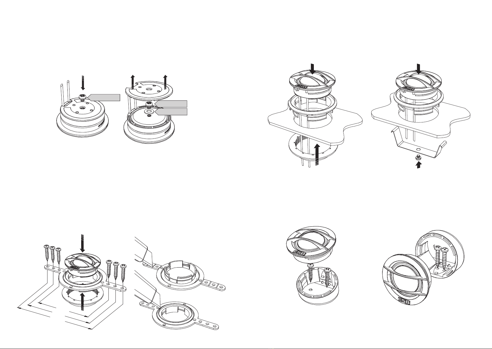
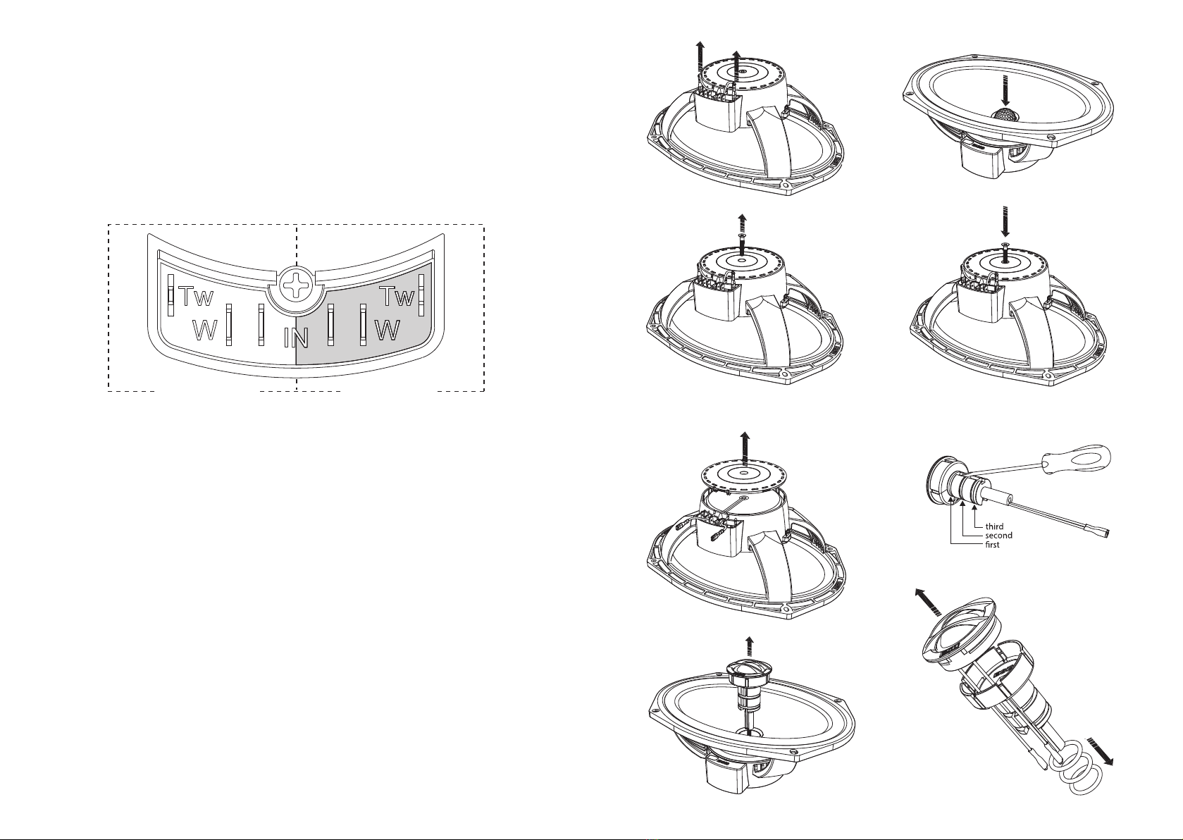
Changing from Coaxial to Separate Components: The 3.165C factory configuration
is coaxial. To change configuration to separate components follow these steps:
1 Unplug the tweeter wires from crossover network (Fig 1).
2 Unscrew the long back screw with T20 Torx screwdriver and remove it completely
(Fig. 2). These screws will be not used on separate system, but can be saved for
go back to previous setting.
3 Remove the back cup cover (Fig. 3).
4 Pull up the tweeter wires in vertical position and remove the entire tweeter and
tweeter holder from the center of woofer (Fig. 4).
5 Now instead of the tweeter holder insert the ABS plug (Fig. 5).
6 Put the rear cup back (note the two pins must be located on two slots on side
wall) and secure everything with the (short) M4x8 mm screw (Fig 6).
7 Tweeter: with a small slotted screwdriver remove the three rubber rings (o rings)
starting from the closest to the tweeter to the farthest. The screwdriver must be
inserted on dedicated slot located opposite the tweeter cables (Fig 7).
8 Lift the cables from the slots where they are inserted and gently remove the
tweeter by pulling and turning slightly. Route the cables through the slot on the
holder. (Fig 8).
At this point the tweeter can be used separately with one of the supplied
accessories. Refer to 3.25 installation manual.
third
second
rst
Fig.
Fig. 2
Fig. 3
Fig. 4
Fig. 5
Fig. 6
Fig. 7
Fig. 8
Black / Negative Red / Positive

3.69C
6 x 9”/150 x 230 mm
Convertible Speaker
Installation Manual
esbcar.com
TECHNICAL SPECIFICATIONS
• Power handling:
240 W peak, 120 W continuous
• Frequency response:
55 Hz 25 KHz +/ 3dB
• Sensitivity:
88.5 dB SPL 1W/1m
• Overall diameter: 168 x 235 mm
Total Height: 83 mm
Mounting depth: 72 mm
Mounting hole: 148 x 215 mm
MAIN FEATURES
• FEA motor optimized
• 25 mm copper/aluminum voice coil
• High temperature aluminum former
• High grade ferrite magnet (woofer)
• N42 neodymium magnet (tweeter)
• Axial forced coil ventilation
• Fiber reinforced paper cone (woofer)
• Hi module silk dome (tweeter)
• Oversized single wave rubber
suspension (woofer)
• Poly cotton spider (woofer)
• Computer designed ABS frame
• Motor metal part CNC machined
NOTE: Make sure that your mounting location will not cause damage to the components of your vehicle.
Check for airbag system location, speaker can’t be located over or close it. Never play this component
without crossover, especially with high powers, this can damage it. Never play the system with amplifier
in clipping or high distortion level. If use a passive crossover, use a dedicated crossover system, don’t
use a generic passive crossover, these are not designed for this speaker impedance and the indicated
cut off frequency may not be true.
Crossover Network: The crossover terminals area are separated as red zone and
black zone: all connectors on red zone are positive (+) and all connectors on black
zone are negative ( ). Wires from the amplifier outputs must be connected on
terminal labeled IN+ and IN . The positive and negative outputs of the woofer
connections are labeled W+ and W on the crossover and should be connected
to corresponding terminals on woofer. The tweeter connections are labeled as TW+
and TW . Wires out of tweeter use black and red insulator tubes, red (positive)
must be connected to TW+. The crossover can be fixed directly to the woofer
frame by a slide joint and locked by a screw, or it can be used separately and fixed
in another place inside the car.
Changing from Coaxial to Separate Components: The 3.69C factory configuration
is coaxial. To change configuration to separate components follow these steps:
1 Unplug the tweeter wires from crossover network (Fig 1).
2 Unscrew the long back screw with T20 Torx screwdriver and remove it completely
(Fig. 2). These screws will be not used on separate system, but can be saved for
go back to previous setting.
3 Remove the back cup cover (Fig. 3).
4 Pull up the tweeter wires in vertical position and remove the entire tweeter and
tweeter holder from the center of woofer (Fig. 4).
5 Now instead of the tweeter holder insert the ABS plug (Fig. 5).
6 Put the rear cup back (note the two pins must be located on two slots on side
wall) and secure everything with the (short) M4x8 mm screw (Fig 6).
7 Tweeter: with a small slotted screwdriver remove the three rubber rings (o rings)
starting from the closest to the tweeter to the farthest. The screwdriver must be
inserted on dedicated slot located opposite the tweeter cables (Fig 7).
8 Lift the cables from the slots where they are inserted and gently remove the
tweeter by pulling and turning slightly. Route the cables through the slot on the
holder (Fig 8).
At this point the tweeter can be used separately with one of the supplied
accessories. Refer to 3.25 installation manual. 3.165C is shown in the drawings, the
procedure is the same for 3.69C.
Fig.
Fig. 2
Fig. 3
Fig. 4
Fig. 5
Fig. 6
Fig. 7
Fig. 8
Black / Negative Red / Positive

3.6K2CX
2-Way Passive Crossover
Installation Manual
esbcar.com
NOTE: Make sure that your mounting location will not cause damage to the components of your vehicle.
Check for airbag system location, this crossover can’t be located over or close it. Never connect with
differente speakers then suggested, this can damage them. Never play the system with amplifier in
clipping or high distortion level.
TECHNICAL SPECIFICATIONS
• Power handling:
300 W peak, 150 W continuous
• Crossover cut off:
3000 Hz
• Slope:
Low Pass 6 dB/Oct.
High Pass 12 dB/Oct.
• Size:
104 (L) x 63 (W) x 27 (H) mm
MAIN FEATURES
• Dedicated to 3000 series speakers
• Large screw terminal
• Ventilated case
• High thickness PCB copper
• 4 step tweeter level adjustment
• Secure screw cover fixing
• Clean mounting system
• Oversize not inductive ceramic resistors
• Polyester tweeter capacitor
• Asymmetrical cutting slope
• In air tweeter and midrange inductor


