ESI ES2247B User manual
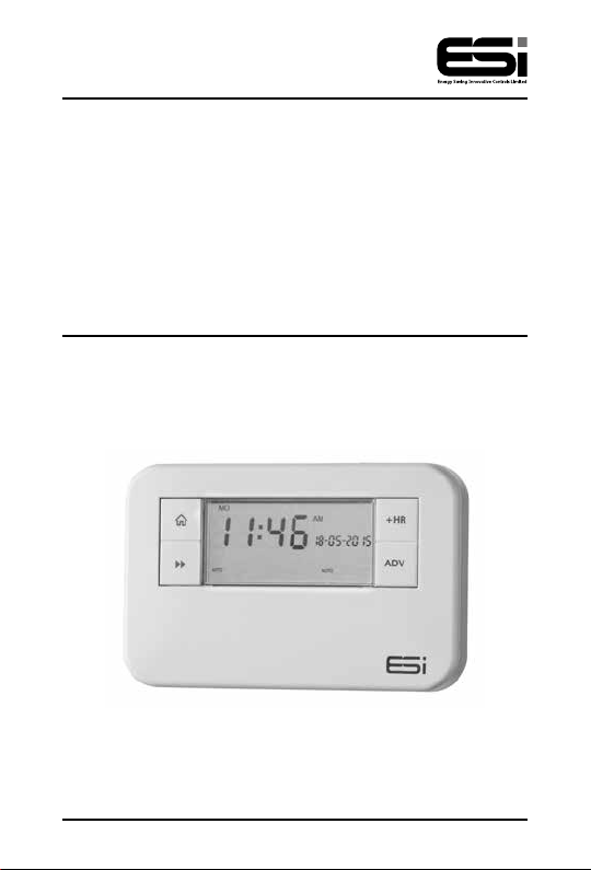
ES2247B
2 Channel Multi-Purpose
Programmer
Installation Instructions

Thank you for choosing ESi Controls.
All our products are tested in the UK so we are
confident this product will reach you in perfect
condition and give you many years of service.
However, for additional peace of mind, we
recommend you register your product online at
www.esicontrols.co.uk/warranty for your
extended warranty.
2

3
Installation Instructions
Technical Data 6
Installation Instructions
Safety Instructions 7
Maintenance 7
Safety Notice 8
Technical Settings 8
Setting the Landlord Service Interval 9
Fitting the Back Plate 11
Entering a New Installer Code 11
Existing Installations 12
New Installations 12
Wiring Diagram 12
Commissioning 13
Contents

4

5
Installation Instructions

6
Power Supply 230V AC, 50Hz
Operating Temperature 0°C to 35°C
Swith Rating 230V AC, 6(2) A SPDT
Battery Type Lithium Cell CR2032
Enclosure Protection IP30
Plastics Thermolatic, flame retardant
Insulation Class Double
Wiring For fixed wiring only
Back Plate Industry standard
Dimensions 140mm(L) x 90mm(H) x 30mm(D)
Clock 12 hour am/pm, 1 minute
resolution
BST/GMT Time Change Automatic
Clock Accuracy +/- 1 sec/day
Programme Cycle 24hr, 5/2 Day or 7 Day selectable
Programme ON/OFFS per day 2 ON/OFF, or 3 ON/OFF selectable
Programme Selection Auto, ON, All Day, OFF
Programme Override +1, +2, +3Hr and/or Advance
Heating System Pumped, Gravity selectable
Complies EN60730-1, EN60730-2.7, EMC
Directive 2014/30EU, LVD Direc-
tive 2014/35/EU
Technical data

7
The unit must be installed by a suitably qualified person in
accordance with the latest IEE Wiring Regulations.
Isolate mains supply before commencing installation. Please
read all instructions before proceeding.
Ensure that the fixed wiring connections to the mains supply
is via a fuse rated at not more than 6 amps and class ‘A’
switch having a contact separation of a minimum of 3mm
in all poles. The recommended cable sizes are 1.0mm sqr or
1.5mm sqr.
No earth connection is required as the product is double
insulated but ensure continuity of earth throughout the
system.
If the unit is fitted to a metal surface, IT IS ESSENTIAL that
the metal be earthed. DO NOT use a surface mounting box
NEVER fit or remove the unit to a live wall-plate.
Maintenance
Always isolate the mains supply before commencing any
work, servicing or maintenance on the system. And please
read all instructions before proceeding.
Arrange for an annual maintenance and inspection schedule
to be carried out by a qualified person on every part of the
heating and hot water system.
Installation Safety Instructions

8
Safety Notice
WARNING!
Always isolate the AC mains supply before installing.
this product must be fitted by a qualified person, and
installation must comply with the guidance provided in
the current editions of BS767 (IEE wiring regulations)
and part “P” of the building regulations.
Technical Settings
1. Move the slider to RUN. Hold down the Home
button, the Day button and the –button (under the
facia) together for 3 seconds to enter the Technical
Setting Mode.
2. Press +/– to choose between 2 or 3 ON/OFFs per day.
3. Press the Next button and press +/– to choose
between Pu (Pumped, allows independent control of
CH and HW) or Gr (Gravity does not allow CH without
HW but can provide HW without CH).
3. Press the Next button and press +/– to choose
between Protection ON/OFF. (If Protection is ON and
the system does not call for heat for one week, the
system will be turned ON for one minute each week
that the system does not call for heat.)
4. Press the Next button and press +/– to choose
between 12 hour clock or 24 hour clock.
5. Press the Next button and press +/– to choose
between Std (standard time with the changeover at
2.50am) or ECON (economy time with the changeover
at 00.00am, midnight).

9
Setting the Landlord Service Interval
1. Switch the slider to RUN.
2. Press Home, Copy and the +buttons together to
enter the landlord settings. A numeric password will be
required to enter these settings.
3. The LCD display will show C0dE. Press the +/– buttons
to enter the first digit of the code. Press the Day button
to move to the next digit. Repeat this until all 4 digits
have been entered and then press the Next button.
N.B. Only when the code entered matches either the pre-set
or master code can the landlord settings be entered. The
factory default code is 0000.
4. The LCD display will show ProG. Press the Next
button and the LCD will show En. Press the +/– buttons
to turn the landlord functions on/off.
5. If landlord functions are turned on, press the Next
button and the LCD display will show SHO. Select on
and the LCD will display ArEA and this will allow a
contact number to be entered. Press the +/– buttons
to set the area code for the maintenance telephone
number. Press the Day button to move to the next
digit. Repeat this until all digits have been entered and
then press the Next button.
6. The LCD display will show tELE. Press the +/– buttons
to set the maintenance telephone number. Press the
Day button to move to the next digit. Repeat this until
all digits have been entered and then press the
Next button.
7. The LCD display will show duE. Press the +/– buttons
to set the due date (from 1 - 450 days).
10
8. Press the Next button and the LCD display will show
ALAr. Press the +/– buttons to set the reminder (from
1 - 31 days). This will then remind the user when the
annual service is due by alternating between displaying
SER and the maintenance telephone number in the
LCD screen according to these settings.
9. Press the Next button and the LCD display will show
tYPE. Press the +/– buttons to choose between: -
0: Reminds the user when the annual service is due
by alternating between displaying SER and the
maintenance telephone number in the screen
according to installer set settings.
1: Reminds the user when the annual service is due
by alternating between displaying SER and the
maintenance telephone number in the screen
according to installer set settings and only allows the
system to run in manual operation for
60 minutes.
2: Reminds the user when the annual service is due
by alternating between displaying SER and the
maintenance telephone number in the screen
according to installer set settings and does not allow
the system to run (permanently OFF).
10. Press the Next button and the LCD display will show
nE. Here a new installer code can be entered. Press
+/– to set the first digit, then press the Day button.
Repeat this for all four digits. Press the Next button
to confirm the changes and the LCD display will show
SET to confirm.
11. Press the Home button or wait for 15 seconds to
automatically confirm and return to Run Mode.
Other manuals for ES2247B
2
Table of contents
Other ESI Programmer manuals


