ESL First One M User manual

ESL audio First One orders & support: [email protected]
First One M power amplifier
module V 1.4
Absolute maximum ratings
Operation beyond these limits may result in
irreversible damage. Table 1:
Recommended operating conditions
Proper module operation within these limits is
guaranteed. Table 2:
Installation and user manual
Description
First One M power amplifier is a compact
medium size ready made single channel Class
AB power amplifier module, carefully designed
for DIY or OEM implementations of the most
demanding audio applications, such as stereo
power amplifiers, monoblock power amplifiers
or active multi-way powered speakers.
First One M power amplifier module is fully
assembled, pre-calibrated and tested in our
production. Measurements and calibrations of
all vital electrical parameters were already
performed in our laboratory, so all that's left to
be done is to mount it to a proper heatsink,
install it into a suitable metal chassis and
connect to a proper DC power supply. Our
recommendation goes to either a switch mode
power supply or classic linear power supply
with minimum of 10 A peak output current per
rail. Properly made wiring connections of the
First One M power amplifier module followed
with short form operating instructions are well
explained in this installation and user manual.
1
Item Symb
ol
Rating Unit
Supply
Voltage
+VDC,
–VDC 65 Vdc
Output
Current I out 16 Adc
Air
Temperature T amb 50 °C
Heat-sink
Temperature T sink 75 °C
Item Symb
ol
Rating Unit
Supply
Voltage
+VDC,
–VDC 40 – 63 Vdc
Load
Impedance Z load 2 – 16 Ω
Air
Temperature T amb 20 – 30 °C
Heat-sink
Temperature T sink 40 – 60 °C

ESL audio First One orders & support: [email protected]
First One M module in stereo connection
In most cases First One M modules will be
used as a part of stereo power amplifier for
which connection diagram is proposed below
(Fig.1), where two First One modules operates
together in a single metal chassis.
Each of the RCA input connectors has to be
electrically isolated from the metal chassis.
Cable connecting RCA terminals to PCB pads
has to be as short as possible, double shielded
coaxial cable of 50 to 75 Ohm impedance is
recommended. Although a twisted pair of a
solid core wires can also be used if an internal
input connection length is shorter than few cm.
Speaker output connector terminals have to be
mechanically heavy duty variant, capable of
conducting high currents. Normally each of
them has to be electrically isolated from the
metal chassis. Internal wiring from power
supply to all amplifier power connections has
to be made by isolated properly coloured wires
of minimal 1,5 mm² cross-section area.
Special attention has to be dedicated to earth
reference point of a metal chassis (Fig.1).
Properly done with electrically well conducted
bolt connected to the metal chassis in a one
point, therefore all the parts of a chassis (all
metal plates, heatsinks) are connected to the
earth potential. GND power supply terminal J2
from each First One module is connected to
GND terminal of its power supply only (Fig.1).
GND potential of both channels are isolated
between each other and earth potential, in this
way modules are prevented from unwanted
ground loops interference currents to flow
between channel's GND potentials.
Powering stereo amplifier can be realized by
single power supply for both channels or by
two power supplies, each for separate channel
in a so called dual-mono configuration. Later is
preferred and recommended as more reliable
and higher performance solution (Fig.1). As
already mentioned the best sonic result is
achieved by using unregulated switch mode
power supply of at least 600 W or more output
power per one First One module's channel.
Fig.1 Schematic diagram for stereo connection
2

ESL audio First One orders & support: [email protected]
Thermal considerations
To ensure proper operating conditions to the
First One amplifier module, temperature of the
main heatsink should never exceed the limit
value of 75°C (Table 1). This is even more
important since module has only two output
transistors, so it is of utmost importance to
keep them at low temperature range at all
times to get best out of their performance.
Therefore heatsink's power dissipation
efficiency must be high, resulting in thermal
resistance of Rth=0,5 K/W or less. Module
(four drivers and two output transistors) is
fixed to the heatsink surface with four M3x12
mm and two M3x16 mm bolts (obligatory use
M3 washers) tightened to M3x10 mm threaded
holes in the heatsink. Output transistors must
be isolated from the heatsink by mica insulator
washer, driver transistors are already isolated.
All six transitor's bottom surfaces needs to be
coated evenly with silicon thermal grease
before fixing the module to the heatsink.
Optional calibrations
Although First One M module is pre-calibrated
in the production, it is highly recommended to
check and recalibrate it prior initial or any new
installation into the chassis. Thus the module's
vital parameters are set to optimal working
conditions in accordance with power supply
selected. Three electrical parameters should be
checked and adjusted if necessary:
VAS idle bias current (18 mA)
output DC offset voltage (0 mV)
supply idle bias current (280 mA)
Calibration adjustments will be correct only if
performed 20-30 min after powering on, when
optimal operating temperature of the module's
heatsink settled around 42-45°C, measured
close to the output power transistors.
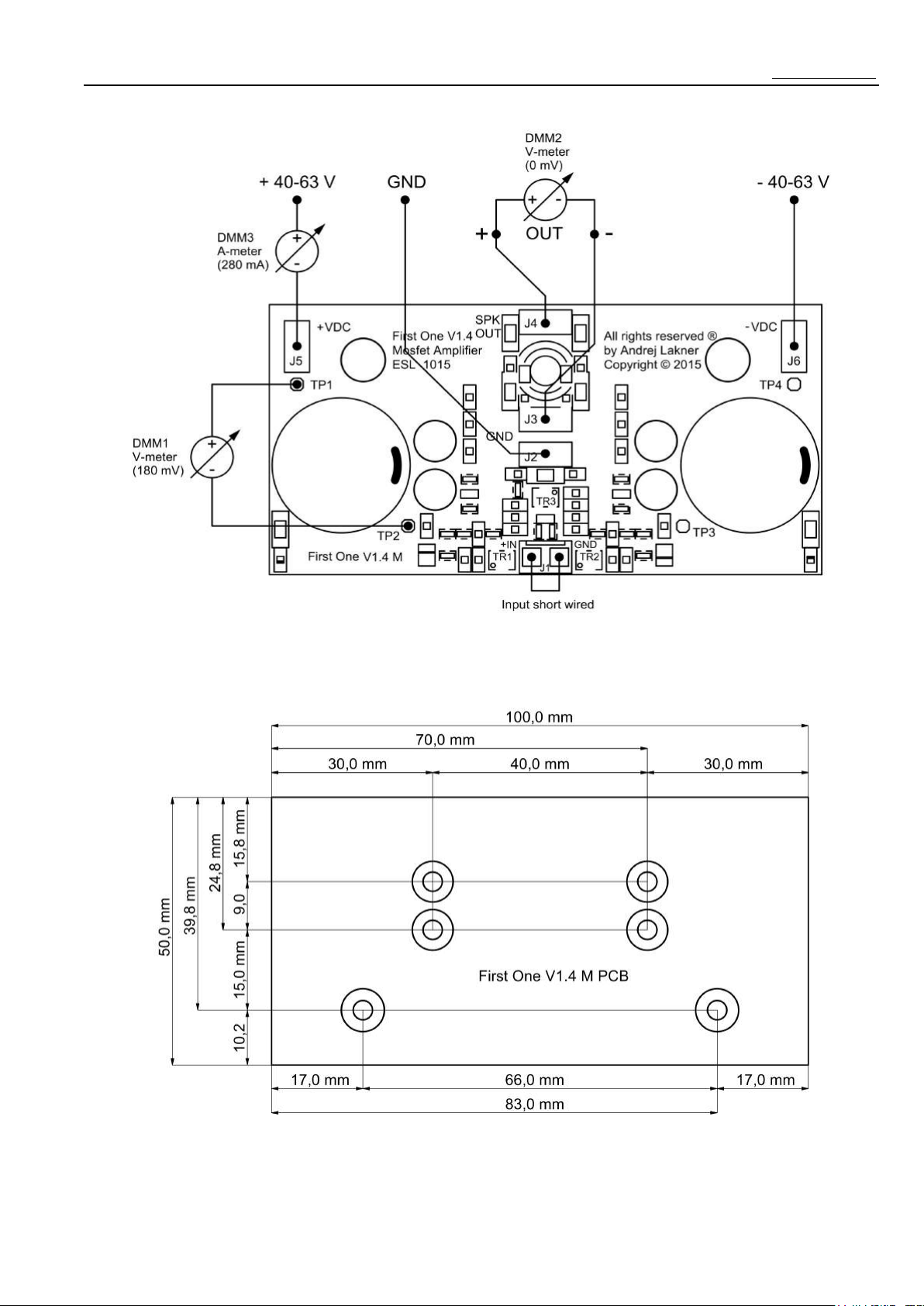
Schematic diagram of calibration adjustment
procedure is shown below (Fig.2), using three
digital multimeters (DMM) will ease the
measuring job substantially. Please be careful
to set all DMM to proper measuring range and
connect them as shown in the schematic.
Trimmers TR1, TR2 serves to adjust VAS idle
bias current to 18 mA (180 mV measured
between TP1-TP2, same between TP3-TP4)
and at the same manner to adjust the output
DC offset voltage to 0 mV.
Description of TR1, TR2 trimmers rotating
adjustments explained as follows:
to increase VAS idle bias current rotate
TR1 or TR2 clockwise
to decrease VAS idle bias current rotate
TR1 or TR2 counter-clockwise
to increase output DC offset voltage
rotate TR1 clockwise or TR2 counter-
clockwise
to decrease output DC offset voltage
rotate TR1 counter-clockwise or TR2
clockwise
Observing the display values of DMM1 and
DMM2 simultaneously will clearly show the
resulting effect of rotating TR1, TR2, so both
preferred target values could be set easily.
Trimmer TR3 serves to calibrate output bias
current, correct value is achieved when
complete idle current consumption of the
module shows 280 mA (DMM3).
If TR3 adjustment changes setting of VAS bias
current or output DC offset, readjust TR1, TR2,
so the correct target values are gained back.
Technical specifications Connectors to use with module
Voltage gain: +27,5 dB J1 – Molex 08-55-0110, contact, crimp
Input impedance: 10 kΩ ll 100 pF Molex 22-01-2035, case housing
Output impedance: 10 mΩ (DC to 20 kHz) J2 – Fast On 6,3 mm, contact, crimp
S/N ratio: > 110 dB (input shorted) J3 – Fast On 6,3 mm, contact, crimp
Output DC offset: +/- 10 mV max. J4 – Fast On 6,3 mm, contact, crimp
Power bandwidth: DC to 100 kHz (-3 dB) J5 – Fast On 6,3 mm, contact, crimp
Output Power: 160 Wrms/8 Ohm max. J6 – Fast On 6,3 mm, contact, crimp
240 Wrms/4 Ohm max.
Overall height: 40 mm (rest of dimensions – Fig.3)
3
ESL audio First One orders & support: [email protected]
Fig.2 Schematic diagram for calibration adjustments
Fig.3 First One module - dimensions
4


