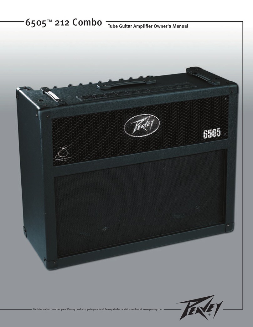
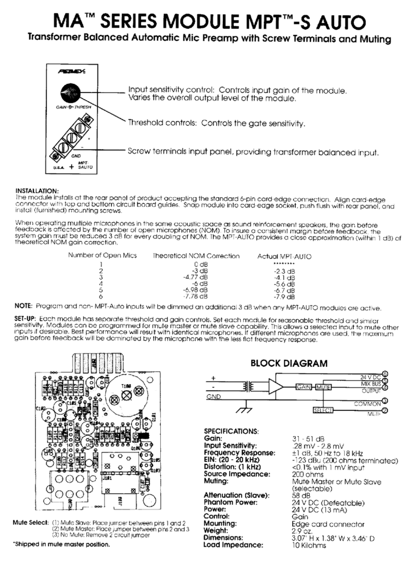
Peavey XR-500 User manual

GENERAL
DESCRIPTION
The
new
XR-500
represents
our
latest
effort
to
combine
professional
features
previously
found
only
in
separate
mixer/equalizer/power
amp
components
into
a
single
compact
ar,o
’ugaea
package.
The
design
of
the
XR-500
utilizes
ihe
latest
advances
n
semiconductor
technology
and
the
overall
circuitry
has
been
designee:
and
optimized
by
use
of
the
latest
computer
aided
design
techniques
Tms
unit’s
Improved
specifications
nave
been
made
posable
by
a
thorough
and
complete
cesicn
effort
resulting
in
ail
new
circuitry
from
the
input
jack
through
lo
the
speaker
output.
The
XR-500
features
five
mdependenl
input
channels
and
includes
a
separate
pfe”
monitor
ser\J
acbve
shelving
type
high
and
tow
equalization,
and
a
"posl‘
effects
sand
on
each
chance!
Master
level
contrc.’s
arc
provided
for
'ho
mao.
rrcoilo’
and
reverb
return
\
lull
seven-bare
graphic
equalizer
has
been
built
into
the
system
and
utilizes
Ihe
most
contemporary
active
filter
circuitry
available
Additional
flexibility
is
provided
by
the
XR-500‘s
patch
panel,
enabling
this
versalile
unit
lo
be
usee
in
cxxiiunclian
with
an
exlremey
v/idu
range
o'
auxiliary
equipment
The
newly
engineered
130-Walt
power
amplifier
features
our
exclusive
DD~^
{'
Distortion
Dotociion
Techniquca")
compression
Circuitry
that
electronically
senses
tne
onset
of
clipping
and
automa?
cany
activates
the
comrressicn
circuit
10
maximize
headroom,
and
prevent
clipp
nc
and
distortion
m
the
power
amp
The
use
of
this
DOT*
compression
circuit
efleciiveiy
increases
the
apparent
headrcom
available.
Ihus
maximizing
every
precious
Watt
of
power
available
This
compresscn
feature
alicv/s
the
XR-500
to
quite
eheclively
compete
with
un
ts
having
conscerably
more
RMS
power
The
power
amp
of
ihe
XR-500
utilizes
lour
high-voltage,
high-speed
TO-3
powpr
devices
bolted
to
a
massive
heatsink
The
internal
power
supply
consists
ol
a
very
large
pov/er
(mains)
transformer
featuring
a
grain
oriented
silicon
steel
core
and
a
high
degree
of
magnetic
shielding
to
mmmizo
extraneous
hum
fields
Siiicor
rectifiers
cornectec
in
3
ful
wave
pudge
feed
powe*
to
large
elect'olytic
Mter
banks
and
provide
considerably
more
music
pov/er
than
the
130-Watt
RMS
power
rating
would
indicate
■
Overall,
ihe
XR-500
brings
protessima
performance
together
m
an
exiremesy
versatile
and
compact
package,
ofiering
features
and
specifications
formerly
available
only
with
separate
componerts
in
a
single
pccable
package.
WARNING:
To
prevent
electrical
shock
or
lire
hazard,
do
not
expose
this
appliance
to
rain
or
moisture.

FRONT
PANEL
INPUT
JACKS
(A)
and
(B)
Each
channel
ol
ihe
XR-500
is
equipped
with
iwo
input
jacks
which
are
connected
in
a
unique
circuit
that
allows
a
wde
range
of
inputs
to
be
handled.
When
only
one
microphone
is
used,
the
"A"
input
jack
is
more
sensitive
than
the
"8"
input
tack
Tnishigh
and
low
gain
featuie
enables
optimum
microphone
matching.
If
a
hgh
output
microphone
is
overloading
the
sensitive
"A'
r-put,
simply
reconnect
this
mike
into
the
low
ga
n
"
B"
jack.
When
two
inputs
are
used
in
oachchannd.
t&e
input
circuit
automatically
baancos
to
equalize
the
gam
m
bolh
A
and
B
jacks
This
simple
out
elective
switching
system
gives
-he
user
much
greater
flexibility
in
choice
of
inpul
sensitivities
and
overload
protection.
CHANNEL
CONTROLS
Each
of
Ihe
XR-500's
five
independent
channels
contain
live
controls
Gain.
Monitor.
Effects
and
High
and
Low
Equalization
CHANNEL
GAIN
CONTROL
(C)
This
control
varies
the
gain
of
the
mput
preamplifier.
This
input
preamp
is
designed
around
a
variable
negative
feedback
approach
and
provides
optimum
dynamic
range
as
well
asextromely
low
noise
operation
This
control
is
used
to
set
the
level
ottherespectivechannels
to
achieve
the
main
ml*.
CHANNEL
MONITOR
CONTROL
(D)
The
channel
monitor
control
is
a
totally
independent
lovel
aejustmen;
used
tor
deriving
the
proper
monitor
mv
It
is
important
that
the
user
be
aware
that
this
channel
monitor
send
is
tot
any
independent
from
ali
other
cnannel
controls
and
feeds
directly
into
Ihe
monitor
buss
whose
output
is
determined
by
the
master
monitor
control
(I).
CHANNEL
EQUALIZATION
CONTROLS
The
channel
equalization
conlrols
are
of
the
active
'shelving"
type
and
provide
15
dE
of
boost
or
cut
in
their
respective
frequency
ranges
These
equalization
controls
are
exfremely
effective
and
will
allow
the
user
tc
achieve
almost
any
Wend
of
high
s
and
low's
with
proper
adjustment
Since
these
EQ
ccrtrois
are
capable
of
a
30
CB
range,
care
should
be
taken
lo
properly
utilize
thei'
capabilities
Excessive
boosting
of
low's
can
cause
"muffled"
or
'boemy"
sounds,
as
well
as
tending
toprematuroly
overload
the
power
amp
becausect
excessivo
low
frequency
power
requirements.
Overbocstng
the
high’s
will
tend
to
cause
a
'strident'
or
"screechy
tonality,
as
well
as
tend
ng
to
emphasize
residual
preamp
noise
and
susceptibility
to
acouslic
feedback.
Care
should
be
observed
when
using
excessive
cutin
either
frequency
range
since
excessive
cutting
may
degrade
the
dynamic
rango
capabilities
of
tho
input
preamp
and
create
poor
tonality
These
channel
equalization
controls
have
been
provided
to
achieve
tonal
balance,
as
wel
as
feedback
control
m
the
individual
channels
''or
Ihe
main
mix
only.
At'
experimentation
should
begin
with
these
controls
set
in
the
flat'
0"
(straight
up
or
t
?:00)
position
Use
of
the
individual
channel
controls
in
conjunction
with
the
ma&er
graphic
equalizer
is
vita
to
provide
the
user
with
optimum
equalization
CHANNEL
LOW
EQUALIZATION
CONTROL
(E)
The
low
equalization
conirol
determines
whether
the
low
frequencies
wil
be
boosted
or
cut
Boost
occurs
in
the
clockwise
settings,
while
cut
occurs
in
the
counterclockwise
settings.
Pat
response
is
obtained
in
the
"0"
or
vertical
position
CHANNEL
HIGH
EQUALIZATION
CONTROL
(F)
The
high
equal
zation
control
determines
whether
the
hgh
frequencies
will
be
boosted
or
cut
Boost
occurs
n
the
clockwise
sellings,
wnie
cur
occurs
In
the
counterclockwise
sellings
Fiat
response
is
obtained
in
the
''O'
1
or
vertical
position.
CHANNEL
EFFECTS
CONTROL
(G)
The
channel
ef
teas
send
control
adiusts
the
signal
level
appled
to
the
effects
mix
buss
which
Iceds
the
internal
reverberation
system,
as
wen
as
the
effects
output
on
the
patch
pone:.
The
overall
settings
of
tho
channel
effects
send
controls
determine
the
amount
of
reverb
drive,
as
wel
as
the
signal
output
level
ava
labte
from
the
effects
output
jack
it
is
important
to
note
that
the
effects
send
control
is
a'
post
type
adjustment
which
is
located
in
the
circuit
after
the
charnel
gain
and
equalization
controls.
The
Lser
should
be
aware
that
use
of
tho
interna
reverberation
system
can
only
occur
when
tho
channel
gam.
the
channel
effects
send,
the
master
revero
relurn
and
the
master
ga
in
controls
are
ail
properly
adjusted
MASTER
SECTION
The
XR-500
master
section
contains
overal
master
level
control
Ihe
master
montcr
conirol
and
the
reverb
return
(tc
master)
centre,
as
wen
as
a
seven-band
graphic
equalizer
and
patch
panel.
As
the
name
mplies.
the
master
controls
operate
os
the
tmal
control
element
-or
ihoir
respective
mixing
busses
and
Ihe
master
graphic
EO
determines
the
final
overall
equalization

AUXILIARY
INPUT
(M)
The
auxiliary
input
provides
access
to
iho
main
nixing
buss
for
patching
in
signals
from
external
devices
such
as
celay
lines
or
extra
mixing
channels
Its
input
impedance
is
22K
Ohms
and
Is
designed
lor
signal
evels
of
approximately
1
Volt
RMS
EFFECTS
OUTPUT
(N)
The
effects
output
has
been
designed
to
deliver
output
signal
from
the
effects
buss
for
driving
various
line
level
devices.
Caution
should
be
observed
when
using
accessory
devices
designed
for
guitar
level
(100
mV)
lo
evoid
overloading
these
devices
with
the
relatively
high
output
signal
eve
available
Irom
the
effects
cut.
Overall
signal
level
is
determined
by
the
selling
of
the
various
chccts
send
controls
of
iho
respective
channels.
This
output
is
of
relatively
low
impedance
2
nd
is
capable
of
approximaiely
4
volts
into
500
Ohms
or
8
Volts
into
higher
lose
impedsnees.
MONITOR
OUTPUT
(O)
The
monitor
output
provides
a
signet
fer
an
external
nonitersystem
anc
isa
relatively
low
outou!
impedance
capable
of
over4
Voitsinto
6CX)Ohms
or
over
8
Volts
inio
higoer
load
impedances
The
level
Is
controlled
by
settings
01
toe
individual
channe
monitor
sends
as
well
as
the
master
monitor
level
control.
MAIN
OUTPUT
(P)
The
mam
output
provides
cutput
from
the
main
mixing
buss.
This
oulput
is
of
relatively
low
impedance
and
is
capable
of
over
4
Veits
RMS
into
300
Ohms
or
over
8
Volts
into
higher
load
impedances
The
output
level
is
determined
by
the
gain
and
equalization
settings
of
the
individual
channels,
as
wen
as
the
master
gain
comrol
GRAPHIC
INPUT
(Q)
The
grapfvc
inpu!
ack
provides
a
means
to
allow
patching
nto
ihe
internal
graphic
equalizer
.'power
smp.
This
|ack
is
of
fhe
switch
ng
type
lha!
normally
picks
up
the
signal
ftem
the
nain
oulput
jack
(P).
When
a
plug
is
insertec
into
ne
graphic
input,
the
circuit
path
is
broken
and
tbs
input
may
now
be
plugged
into
ether
devices
or
any
of
tie
output
jacks
of
the
XR-500
The
graphic
input
provides
much
greater
flexibility
m
allowing
the
internal
graphic/power
amp
to
be
utilized
as
a
monitor
smp
or
ter
any
other
purpose
the
usermay
deem
necessary.
Its
input
impedance
is
approximately
50K
Ohrosal
approximately
I
Volt
signal
level
for
full
power
output
at
the
speaker
jacks
REAR
PANEL
FUSE
(U)
T
he
fuse
Is
crated
within
the
cap
of
the
fuseholder
it
is
necessary
that
the
luse
be
replaced
with
the
proper
type
and
value
if
1
should
far.
m
order
lo
avoid
damage
to
Ihe
equipment
and
to
prevent
voiding
the
warranty.
II
your
unit
repeatedly
blows
fuses,
it
should
betaken
10
a
aja’itied
servee
center
‘cr
repair.

MASTER
LEVEL
CONTROL
(H)
The
master
level
centre*
ad/js'.s
Ihe
gain
of
the
mam
mixing
Olss
arcl
determines
ihe
level
ai
the
mam
line
output
:3CK
(P|.
as
well
as
determining
the
signal
lave!
applied
to
:ho
input
of
the
graphic
equalizer/power
amplifier.
It
is
generally
good
practice
to
operate
Ihe
master
level
control
somewhere
in
the
middle
of
its
operating
range
to
allow
maximum
flexibility
in
adjusting
overall
levels
ie
.it
spaw
oracticetorur
the
individual
channel
gains
way
up
and
the
master
contra
way
down
since
this
effectively
negates
flexibility
afforded
by
themaster
control
MASTER
MONITOR
LEVEL
CONTROL
(I)
The
master
monitor
conirol
adjusts
the
gain
of
the
monitor
mixing
buss
and
determines
the
level
of
Ihe
signal
available
from
the
monitor
output
lack
(O;
The
operat
or
of
this
control
and
its
independan!
channel
sends
is
identical
to
that
of
the
main
with
Ihe
exception
Inr
its
ouiput
is
applied
to
the
monitor
line
oulput
jack
instead
of
the
main
output
jack
MASTER
REVERB
RETURN
CONTROL
(J)
The
master
revere
control
determines
ihe
amount
o'
delayed
signal
(reverberaiion)
nal
is
mixed
back
into
the
mam
mx
buss
"he
action
of
this
conirol
{J)
is
defeated
by
use
ot
3
remote
switch
being
plugged
into
the
footswitch
jack
(L)
located
on
tne
patch
panel.
It
is
important
to
note
lhal
no
reverberation
wii
occur
unless
tne
infernal
delay
line
is
being
fed
signal
'rom
me
channel
effects
send
controls
The
master
reverb
return
control
does
not
affect
Ihe
level
available
'rom
Hie
effects
output
ack
totaled
on
the
patch
panel
(N<
GRAPHIC
EQUALIZER
(K)
~hc
so/en-band
equalizer
is
of
the
latest
active
type
and
exhibits
performance
ccmparaoie
to
that
lobncJ
in
the
finest
commercial
equipment
Tne
graphic
equal
zer
is
located
m
the
circuit
just
before
the
internal
130-Watt
power
amplifier
and
provides
a
very
versatileand
professional
equalization
of
Ihe
overall
system
Because
of
the
flexibility
bu»l
into
the
XR-500
several
difler'em
modes
of
operation
are
possible
NORMAL
MODE
Undor
normal
operating
ccnd:
ons
(no
paich
connections),
the
oquslizor
is
connected
through
the
graphic
input
switching
jack
to
the
main
output
which
is
the
signal
derived
from
the
main
mixing
puss
and
controlled
oy
the
master
gain
contro
MONITOR
OPERATION
The
graphic
equalizer
and
internal
pov/er
amp
maybeusedtc
power
a
mon
tor
system
by
simply
patching
hom
the
montorcutputto
the
graphic
input
using's
short
shielded
patch
cable.
When
this
patch
is
acomplished.
the
signal
from
the
main
mixing
buss
is
available
only
at
Ihe
oulput
jack
on
the
patch
panel
(P)
to
be
used
in
coniuoction
with
external
power
amps,
equalizers,
cr
ether
accessories.
MASTER
EQUALIZATION
The
master
graphic
equal'ze*
a
designed
to
provide
room
equalization,
effective
Ieedback
control,
and
overall
system
tone
conirol
It
is
important
to
note
that
there
are
ro
firm
operating
instructions
that
win
result
in
the
ideal
FQ
fereaon
and
every
set
of
operating
conditions
Experimentation
with
adequate
understanding
of
Ihe
graphic
equalizer
is
necessary
to
achieve
optimum
resuits
No
amount
of
equalization
will
correct
an
acoustically
bad
rcom/mike/speaker
a-rangemont
or
completely
correct
the
response
curve
o‘
a
poor
loudspeaker
Ploase
make
sure
the!
the
power
amplifier
has
adequate
headroom
to
handle
any
boost
that
may
be
incurred.
If
you
bcoa;
100
Hz
by
3
dB.
your
power
requirement
will
double.
As
an
example,
if
your
no-mal
performing
level
requires
100
Watts
the
power
requirement
alter
a
3
dB
equalization
boos!
will
be
200
Walls.
You
should
always
begin
operation
with
tne
equalizers
in
the
“0"
or
center
position
it
is
wise
io
avoid
excessive
cutting
of
la'ge
segments
of
the
audio
psssband
since
this
tends
to
reduce
tho
dynamic
range
of
the
system
Also,
it
is
better
ic
raise
the
level
conrcl
rstner
than
to
use
ihe
majority
of
ihe
equalizers
m
the
ooost
position
since
a
lower
overall
signa-to-noise
ratio
will
result
As
with
any
equalizer
dev.ee,
careful
experimentation
and
a
little
common
sense
will
yield
Ihe
desired
result.
NOTE
IF
AN
EXTREME
AMOUNT
OF
BOOST
IS
REQUIRED
AT
A
CERTAIN
BAND
OF
FREQUENCIES.
CHECK
FOR
PROPER
PHASING
OF
YOUR
SPEAKER
OR
POWER
AMPLIFIERS.
IN
MOST
SPEAKER
SYSTEMS,
THE
CROSSOVER
LEVEL
IS
ADJUSTABLE.
IF
YOU
SEE
A
NOTICEABLE
LEVEL
CHANGE
AT
THE
CROSSOVER
POINT,
TRY
TO
COMPENSATE
FOR
THE
LEVEL
DIFFERENCE
WITH
THE
CROSSOVER
CONTROL.
FEEDBACK
CONTROL
A
graphic
equalizer
can
be
used
togreai
advantage
for
feedback
suppression
The
whole
point
ot
equalization
is
to
obtain
the
Highest
system
gain
before
feedback.
In
essence,
this
requites
a
speaker
system
lo
be
as
flat
as
possible
The
following
procedure
is
given
as
a
guide
only!
Use
common
sense
and
take
your
time
when
attempting
the
equal
zalion
process
end
ycur
chances
of
obta-ning
the
desired
results
w
H
be
Very
good
Adjust
all
ehanne
equalization
and
the
graphic
equalizer
controls
for
an
indicated
flat
response,
and
slowly
bring
up
Ihe
level
by
use
of
ihe
channel
o-
master
level
controls
uniil
ihe
system
stans
logo
into
feedback.
Then
very
slowly
adjust
each
section
of
the
graphic
equalizer
unn
you
'md
tho
one
:rot
has
Ihe
moot
effect
or
the
feedback.
Return
all
other
sections
to
the
Mat
position
and
oring
up
the
gam
until
:he
system
apain
goes
into
feedback
Repeat
the
procedure
and
equalize
out
the
second
and
third
'eedoack
modes
and
mo'e
it
necessary.
WARNING
1
You
should
never
have
lo
cul
more
than
6
la
9dB
or
der
normal
conditions.
If
mcrecui
is
necessary,
check
(or
p<oper
phasing
of
the
speaker
system
sndmicrophorepositionirg.
One
improperly
phased
speaker
can
cause
unordingrcodoack
problems.
Do
not
cxocct
to
obtain
a
system
that
is
completely
tree
of
feedback
A
simple
I
-octave
graphic
equalizer
can
only
do
so
much
in
short.
don't
expect
miracles...
PILOT
LED
(R)
The
pilot
LEO
indicates
when
the
electrical
supply
is
switched
on
and
is
actually
delivering
power
to
the
amplifier
“DDT®”
COMPRESSION
WITH
LED
INDICATOR
(S)
The
XR-500
is
a
compact
ard
powerful
system
which
features
a
130-Watt
RMS
power
amplifier
with
a
new
type
of
dynamic
compression.
The
compression
effect
enables
us
to
maximze
the
performance
of
the
amp/speaker
combination.
We
have
determined
ihrough
research
Tat
me
compression
circuitry
sheutd
prevent
ihe
emp/speaker
comb
naiion
from
runningcutot
headroom
(c
apping)and
should
be
as
simple
to
operate
as
possible
to
avoid
undue
complication
for
the
user.
Because
of
the
dynamos
of
a
typical
sound
system,
il
is
q.nte
common
io
activate
the
compression
as
indicated
by
ihe
limit
LED
(light
emitting
diode)
(S|
virtually
constantly
durina
a
performance
since
this
is
what
it
was
designed
toco;
i.e.
to
maximize
the
dynamics
available
Iron',
tne
amp
within
its
powei
oulpu:
capabi
ikes.
We
have
not
irtc.uced
ether
compression
controls
since
wa
have
designed
an
exclusive
“Distort
bn
Detection
~echniquc
1
(DDT*)
circuit
that
senses
conditions
mat
might
cause
overload,
and
compression
;s
activated
only
when
clipping
is
imminent
This
technique
effectively
utilizes
every
precious
watt
available
f'om
the
power
amplifier.
XR-500
PATCH
PANEL
The
patch
pane!
of
the
XR-500
has
been
designed
to
allow
use
of
auxiliary
accessories,
mixers
power
amps.
etc.
in
can;unction
with
this
unt
FOOTSWITCH
(L)
The
footswitch
jack
provides
sc
input
to
accommodate
Ihe
optional
remote
reverb
cuto'f
pedal.
This
foots
witch
iack
is
conventional
and
should
preseni
nc
operational
problems.

POWER
SWITCH
(V)
On
domestic
units,
the
pcMer
switch
is
of
the
three
position
type
with
’.he
cente'
position
being
“OFF
"
This
switch
has
two
ON'
positions,
one
ot
which
is
used
to
ground
the
amplifier
properly
One
cf
the
ON”
positions
wi
i
yield
the
lowest
amount
of
residual
hum
or
''popping"
when
the
instrument
is
touched
and
this
is
the
position
that
should
be
used
On
export
models,
we
utilize
a
simple
on/ot'f
switch
that
does
not
have
multiple
'ON'
positcn3
since
the
grounding
(earthing)
condilions
m
most
foreign
countries
are
positively
made
through
staroard
tanper-prenf
plug-m
systems
LINE
CORD
(T)
For
your
sa-Gtv.
we
have
ncorporatec
a
three-wire
lire
(mams)
cable
with
proper
grounding
facilities
It
is
not
advisable
to
remove
the
Qround
pin
under
any
circumstances.
1
it
is
necessary
lo
use
the
amp
n
a
tv/o-pm
plug
system
wihout
proper
grounding
facilities,
suitable
grounding
adaptors
should
be
used.
Much
less
nose
anc
greatly
reduced
shock
hazard
exists
when
-he
unit
is
operated
with
the
proper
grounded
receptacles
SPEAKER
OUTPUTS
(W)
The
speaker
output
jacks
are
ot
the
s'andard
'/•'
type
Both
the
output
jacks
are
wirec
in
parallel
and
either
or
belli
may
be
used
when
connecting
your
speaker
system.
The
260C
module
has
been
optimized
fora
4-Ohm
lead
but
has
adequate
performance
to
drivo
loads
both,
above
an3
below
the
-ecommendod
>1-Ohm
impectence.
bxtreme
care
should
be
used
when
operating
s
unit
ai
below
4
Ohms
since
lower
load
impedances
lend
to
overload
the
power
amplilier
and
may
cause
premature
activation
of
the
power
amp's
short
circuit
protection
system
and/or
thermal
fault
protection
circuitry.
Because
of
the
unique
design
of
the
compressor,
the
circuit
will
still
minimize
clipping
regardless
of
load
values
LINE
(MAINS)
CORD
RETAINER
(X)
We
have
provided
two
srge
molded
line
cord
retainers
on
the
rear
panel
to
allow
storage
Of
the
mams
cable
for
navel.
In
operation,
the
cable
should
be
completely
unwrapped
to
allow
maximum
heat
dissipation
from
the
rear
pane:/heatsink.
MONITOR
REVERB
UNIT

V
HIGH
MOISf
LEVELS
MAY
CAUSE
A
PERMANENT
HEARING
LOSS
INO>VIOUAIS
VARY
CONSIDERABLY
IN
SUSCEPTIBILITY
TO
NGISE
INDUCED
HEARING
LOSS.BUT
LOSE
SOME
HEARING
If
E»POSEO
TO
SUfFICIENTlY
INT6N36
NOSE
FOR
A
SUFFICIENT
TIW6
OCCUPATIONAL
SAFETY
ANO
HEALTH
ADMINISTRATION
<OSHA>
HAS
SPECIFIED
THE
FOLLOWING
PERMISSIBLE
NOISE
LEVEL
EXPOSURES
DURATION
PER
OAY
IN
HOURS
SOUNO
LEVEL
Ml.
SLOW
RESPONSE
lEARLY
EVERYONE
Wl
HE
U
S.
GOY6RNAIEN'
ACCOROIN-
EXPOSURE
IN
ElN
THE
EAR&
HEUMrrsAa
Of
THE
AUG
fi
OVER
THE!
RSIIS5IBI
MUST
BE
EAR
FLU
EXPOSU
ABOVE
;o
hioi
PPOTEi
(O3E0
TO
Bi
FRAT1CN
iDUONQ
CAUTl.
OR
PLAYING
i
SYSTEM
Cl
IE
THAT
MAX
Y/HICH
VAY
E
l
AT
ASS
OBTAIN^
THIS
A*
HANOI!
|ATEO-
IPEAKER
PLEASE
CONTRl
it
Mloie
i*l
Mover
Xooyolt
tr®
grontd
pinon
tr®
(Oarer
-up(A)
cord
Fat
mo'll
mlomralior
c"
ground
ryj
w"lf
lix
our
1r«*
bocKlel
‘S"c«»
Hentdind
Orcrjndi*;
"
•*c"vw
sj(t«r
cons
Vouio
al«e>»
Be
Handled
c?<elull»
N^Ypr
«“
«
OI
DWfe
ei*»Cmeri
o"
po-er
»i*s>ly
ODtily
Per-adrciUy
cHcc“
co'di
ice
emicr
agnsot
jOcm.
C3iX>:<alv
m
lie
(Hug
and
ihe
ooml
-*w
ihe
eo'd
eota
1
"e
unit
T"e
boyi-cy
mcE
ly
cord
sncuid
oe
unt)luogc3
when
IK
unri
15
10
Da
unisod
lor
1
J'g
&&'icdso*
mho.
Mam
pent
can
o«
domed
win
a
damp
«»g
tn«
virryi
ton'lng
mad
on
lotno
uniticatiMotei'ttJwRhiOa'nprag.
Oi
in
ammonii
onto
nou»*HMd
c
*srvr«
•
nacatssir
namiria]
cdonoifalf)
oila
r
oponlo^i.
11
Tii*
undtiidixaoechaoad
b/i«u«
<*.1
Mines
technician
2
AH
dUiMy
and
Operating
Instruction!
irianld
be
raianad
*ci
luf.u-
relaieiKA
3
OBey
iMl
csulloni
m
lh«
oattrrlmg
iMtrueiO"!
.wt
on
(he
bach
cf
it»
urn
*
All
cpanli-fl
Ii3iu*t->ni
ihe-M
te
leld-ed
3
Thu
picUuol
rlwuld
nol
bit
u»ca
ami
■
ale'.
ie.
a
bBifiliiO.
>n+
swimming
pool,
wti
Oaoomoni.
etc.
e
Tru»product
wiauio
be
ioc«od
so
vwt
«»ocantondcaa
*0»
inieeteie
«im
He
proper
vmbiauon
11
altcuHl
001
Da
pix.ud
1101
isainjl
a
a
all
ai
piece
in
a
DU'lt
m
pnclomra
”J»
wil
tmpcco
IK
now
01
cecang
-jtr
f
Tril»
proa
niWcuV
hoc
Pc
placed
nea'a
i©ui«ec«n*m»ijch
as
a
atovc.
naattY.
.
..
A
Th.
poMr
ftippi
cord
or
plug
Ha*
In
NT
damng-d
B.
Anything
nni
lallan
di
been
id
lied
.nlo
if®
m»t
C.
Tne
unt
Coes
no*,
epriateconecRj
O
The
1
»
1
|
Niowi
am
Wind
or
IK
mclOSul*
OJitwqw
th*
uim
anooie
net
ittemot
to
i«ve*
m®
oqu
o-nem
as
sendee
werh
inoud
be
c
one
oy
a
quant
eo
serve*
losrtmcmn
tadiatot
or
abb
it®
1
noil
ptcduclng
CHANNELS:
5
INPUTS:
10
High
Z.
5
being
high
gam,
5
being
padeed
(-6
dB);
Graphic
inpul;
Auxiliary
input
SENSITIVITY:
Waster.
Channel
Gain
@
Vertical
(12.001
settings.
All
EQ
flat.
100
mV
mlo
High
Gam
tor
130
W
RMS
@
speaker
oufpul
into
A
Ohms
MAXIMUM
DYNAMIC
RANGE:
3
V
RMS
@
Jack
A
6
V
RMS
@
Jack
B
MAXIMUM
GAIN:
66
c!B
with
channel
Gain
lull
CW
80
CB
with
channel
Gam
and
Master
Level
full
CW
INPUT
IMPEDANCE:
220
K
Ohms
(Jack
A)
44K
Ohms
(Jack
B)
SIGNAL-TO-NOISE
RATIO:
Master
@
12:00.
Ail
EO
flat.
20
Hz
-
20
kHz
unweighted;
1
channel
Gain
@
12
00
22K
Ohm
source.
78
dB
All
channel
Gams
@
12
00.
22K
Ohm
source.
74
dB
CHANNEL
EQUALIZAION:
-
-15
dB
@
80
Hz
&
8
kHz.
Shelving
Characteristic
MASTER
GRAPHIC
EQUALIZER:
*-15
dB
@
100
Hz.
200
Hz.
500
Hz.
1
kHz.
2
kHz
5
kHz
and
10
kHz,
Peak/Notch
Characteristic,
Average
"Q”
of
1
8
TOTAL
SYSTEM
FREQUENCY
RESPONSE:
*-2
dB.
40
Hz
-
20
kHz.
All
EO
flat
LINE
OUTPUTS:
Main.
Monitor
and
Effects
MAXIMUM
OUTPUT:
8
V
RMS
into
I
OK
Ohms
(+18
dBV)
or
4
V
RMS
mto
600
Ohms
(->
14
dBM)
POWER
AMP
SPECIFICATIONS
RATED
POWER:
130
W
RMS
into
4
Ohms
load
POWER
@
CLIPPING:
(1%
THD
@
I
kHz.
120
V
VAC
line)
Typically
85
W
RMS
into
8
Ohms
140
W
RMS
mto
4
Ohms
90
W
RMS
into
2
Ohms
FREQUENCY
RESPONSE:
»0
-1
dB.
10
Hz
-
30
kHz.
100
W
RMS
into
4
Ohms
TOTAL
HARMONIC
DISTORTION:
Less
lhan
0.1%,
10
mW
to
100
W
RMS.
20
Hz
10
kHz
4
Ohms.
Typically
below
.05%
INTER
MODULATION
DISTORTION:
Less
than
0.1%.
10
mW
to
100
W
RMS.
60
Hz
&
5
kHz
4
Ohms.
Typically
below
04%
eo»?an
Ci
479
Other Peavey Amplifier manuals

Peavey
Peavey NASHVILLE 1000 User manual

Peavey
Peavey Ultra 60/120 User manual

Peavey
Peavey Blazer 158 User manual

Peavey
Peavey Audition Audition Chorus User manual

Peavey
Peavey PA600 User manual

Peavey
Peavey DECA 528 User manual

Peavey
Peavey T.B. RAXX User manual

Peavey
Peavey IP 1.3K User manual

Peavey
Peavey CS 1200H User manual

Peavey
Peavey Studio Chorus 210 User manual

Peavey
Peavey TNT 130 User manual

Peavey
Peavey UA 5 User manual

Peavey
Peavey MA MPT-S AUTO User manual

Peavey
Peavey Valve King Series User manual

Peavey
Peavey MMA SERIES User manual

Peavey
Peavey SA 4200 User manual

Peavey
Peavey Combo 210TX User manual

Peavey
Peavey VMP 2 User manual

Peavey
Peavey Special 112 User manual

Peavey
Peavey IPS 800 User manual