Etabeta electronics NT Series User manual

L R
+10
+4
+2
0
-2
-4
-22
-38
-60
-16
-7
CLI P
ST
15 /1 613 /1 4
NT series digital mixer
NT-16
Operating instruction

Safe Use Matters
Before using the device, please read the instruction manual carefully and follow the warnings
about operation and use. The instruction manual should be kept for future reference.
◆The device can only use the power supply type marked in the manual.
◆ Attention should be paid to avoid the power cord being squeezed by heavy objects,
especially attention should be paid to the plug of the power cord, the outlet of the
device and the convenient socket, and avoid pulling or pumping the power cord.
◆ Can not be used near the water source, such as: bathtub, sink, kitchen sink, wash
basin, wet basement, swimming pool, etc.
◆ The device must be away from heat source.Examples: radiators, heating resistors,
stoves and other heating devices (including amplifiers).
◆ Care must be taken to prevent objects or water from falling into the inner core.If
dropped into metal or other conductive material, there is a risk of electric short circuit
inside the device.
◆ Because the machine memory has high voltage, non-electronic professional and
technical personnel, do not remove the casing, if the internal electronic parts are
abnormal contact, serious electric shock may occur
Reason.The company is not responsible for this incident.
◆ Do not use volatile solutions.Such as: alcohol, paint thinner, gasoline, volatile oil and
other wipe the shell, the use of clean dry cloth.
◆ In case of abnormal odor or smoke, cut off the power supply and pull out the plug
immediately, and contact the supplier or the nearest maintenance department for
maintenance service.
In pieces A.For safety, please disconnect the power switch and unplug the power plug.In
case of fire.
B.To prevent water, metal, flammable products or other foreign matter from falling into
the machine, so as to avoid electric shock and fire accident.In case of such an accident,
please cut off the power immediately.
Discontinue use.And with the company's service center or the purchase shop contact,
seeking maintenance services.
◆ Do not put the power plug under the machine or between other items;Do not set the
power supply in the place with frequent traffic, so as not to cause damage to the plug
An electric shock or fire accident occurs.
Warning:
Do not press the power plug under the machine or between other items;Do not set
the power in the personnel come
To frequent places to avoid electric shock or fire accidents caused by broken plugs.
!
1

Customers need to know
Dear customers,
Thank you for choosing this product!In order to ensure the safety of you and the machine, as
well as to enable you to fully enjoy the best product experience, be sure to read this manual
carefully before connection or operation, and please keep this manual for future reference after
reading.
Open-box inspection:
After unpacking, please first confirm whether there is any damage caused by transportation,
and connect the wire according to the requirements of this manual and test each function. If
there is any problem, please inform the sales department immediately.
Note:
◆ When buying the machine, please check whether the bar code on the back plate
of the case is complete, and whether the random accessories are complete.
◆ Non-designated maintenance department opened the machine will not be
within the scope of the three packages.
◆ It is recommended that you keep the removed packaging materials and
accessories for future handling or maintenance.
!
Directory
2
Begin to use·················································································································································· 4
Function is introduced····························································································································· 6
Input channel··············································································································································· 11
The effect of channel································································································································ 12
Marshalling channel································································································································ 13
The auxiliary channel······························································································································· 14
Digital channel············································································································································· 15
System Settings··········································································································································· 16
Mp3 page························································································································································ 16
Load/save mode··········································································································································· 17
Copy the page················································································································································ 17

The machine features
This product is a novel and unique multi-function digital mixer, with small size, light weight, full
function, intuitive and simple operation, quick response and many other advantages.
Application scenarios: performance, conference, rental, school, church, cultural hall, wedding,
concert, family, band and other occasions.
1.12 MIC input 1 set of stereo input,1 digital input: optical fiber/sound card, MP3
2.Input channel audio and image adjustment
3. MIC input gain adjustment (digital gain)
4. +48V phantom power supply (MIC channels can be opened and closed
independently)
5.Built-in noise door, pressure limiter, high and low pass, 5-section parameter balance,
delay, sound and image balance adjustment of transmission channel
6.Fast copy of channel parameters
7.Input and output EQ ON/OFF
8.Multi-function knob
9.Each channel is equipped with multi-function menu, dumb voice and monitoring
10.The channel is equipped with 100MM electric push rod, signal, peak light (13 ALPS
electric push)
11.8 signal output (main output L,R,4 AUX output,2 marshaling output)
12. AUX output (Push front/rear)
13.Output processing: high and low pass filtering, 12 section parameter equalization,
compressor, delay, phase
14.Digital recording function
15.Users can customize the layer, output mixed editing function
16.Double row 3 color 12 level indicator light
17.Built-in sound card (MP3, PC directly play music)
18. Four quick scene invocation modes and 20 scenes storage
19. Storage and fetching of user parameters (can be managed on PC)
20. Built-in two-channel dual-DSP effector
21. FX foot switch interface
22. Optical fiber input/output
23. Multi-operating system control software (IOS system, Android system, Windows
system)
24.support wired network port adjustment (or external router wireless adjustment)
25.5 inch touch screen
3

Quick to use
1. When the mixer is turned off, select one MIC/ LINE input channel, plug in the microphone or CD
player and other external audio source to connect to the mixer, please make sure before connecting
Keep the access channel mute or push the physical push to the lowest position.
2. Access the L/R main output interface at the back of the mixer with the audio casson cable, and
connect the power amplifier at the other end to the speaker.
3. Switch on the power supply and turn on the mixer, wait for the mixer to completely start up, and
then turn on the power amplifier.
4. After starting the mixer, push the physical pusher inserted into the MIC/ LINE input channel to the
appropriate position.
5. Then also push the physical pushers of the main output to the appropriate position.
6. Adjust the input gain of the input channel to make the input signal achieve the appropriate dynamic.
7. If you are connected to a capacitive microphone or other device that requires power, turn on the
Phantom Power.
8. According to the demand of the signal source, the equalizer is used to enhance or weaken the
corresponding frequency band, and the compressor and threshold are used to control the dynamic
range.
9. Send input signals to each effector, output bus and main output.
10. Change the main push until the sound system produces the right amount of sound.
4

Quick to use
12
12 11 10 9 8 765432 1
12
MAI N OUTPUT AUX O UTPUT
SUB O UTPUT
3
4
FOO TSW
RS 232
R T G
LI NK IN-S /PDIF-OU T
Moving coil microphone
o
45 Back to listen Listening to the ultra-low
Stereo line input
LR
Gooseneck microphone
Wireless microphone
The central control
The router
5
Features - Front panel
L R
+1 0
+4
+2
0
-2
-4
-2 2
-3 8
-6 0
-1 6
-7
CL IP
ST
15 /1 613 /1 4
123
4
5
6
7
8
9
10
11
12
13
14
15
16
17
18
19
20
1
111
2
222
6

Features - Front panel
1. Channel COMP/ limiter
1). This knob can adjust the threshold size of the pressure limiter. When the pressure limiter switch is
opened, the adjustment is effective.2). In button is to open and close the limiter.
2. Channel EQ/ Equalizer
1). Equalizer parameter knob
Up to down means: gain, frequency and Q value.
2). Parameter equalizer button
The shortcut keys of the parameter equalizer are: treble, medium treble, medium, bass and bass (from
top to bottom). After lighting the corresponding keys, match the three parameters on the left
Adjust the knob to adjust the EQ parameters,
Note: EQ adjustment is only effective when the EQ switch (ON key) is turned ON.
3. channel HPF/LPF(high-low pass filter)
1).(HPF) high pass knob/high pass switch
Adjust this knob to reduce the low frequency signal, HPF button is high frequency on and off.
2).(LPF) Low Pass Knob/Low Pass Switch
Adjust this knob to reduce the high frequency signal, LPF button is low pass frequency on and off.
The high-low pass filter can be treated as a frequency divider
4. Input channel GATE/ noise GATE
This knob can adjust the threshold size of the noise door. The IN button is to open and close the noise
door.
5. Input channel gain/audiovisual control knob
1). Gain control
Adjust this knob to increase or decrease the input signal level.
2). Audio and video control knob
Controls the proportion of signals sent from the current channel to the main output L channel and R
channel.
6. Channel signal routing and sending
1). The current channel signal is sent to the main output channel L and channel R (just light up).2). The
current channel signal is sent to the marshalling output SUB1-2(just light it up).
7. Channel signal indicator light
1).PK peak indicator
This is used to indicate that the channel's signal is approaching distortion (restricted).
2).0 signal indicator light
The light is on, indicating that there is a signal input on this channel.
3).SIG signal indicator
The light is on, indicating that there is a signal input on this channel.
8. channel selection key/mute key/listening key
1).SEL channel selection key
The button lights up to indicate that a channel has been selected and that channel parameters can be
edited.
2).ON mute switch
Channel mute switch. When off, it means the channel is in mute state and you will not hear the signal of
the channel
3).PFL monitor switch
When this button is pressed, the signal will be output from the listener and the headset.
9. Passage pushers
This is used to control the level on the current channel (electric push).
10. Main output push
Used for adjusting the size of the hybrid main output level (electric push).
7

Features - Front panel
11. Push mode button (signal routing)
1). Main key in push mode
When the MAIN light is on, it means that the current push is at the push level of the corresponding channel, and this level is
controlled by the push level of the corresponding channel.
Long press this button to lock the mixer. At this time, the channel parameters will not be adjusted. Long press again to unlock.
2). AUX1-AUX4 output by pushing mode button
When the page-turning button IN is lit, press the AUX button to flash, and the pusher is IN the signal level state sent from the
input channel to the corresponding AUX auxiliary output.
The transmission size is controlled by the pushers of the corresponding channel.
3). Push mode button FX1 / FX2
When the page-turning button IN is lit, press the FX1-FX2 indicator light flashes, and the pusher is IN the input channel and
sends to the signal level corresponding to FX1-FX2.
The send size is controlled by the push of the current channel.
4). Tap effect tempo button
Effect 1: Short delay in delay Long delay is the metronome effect,
Effect 2: Delay click the Tap button to change the echo delay time of the speed effect in a short delay.
12.input/output channel push page turning button
1).GEQ- When the output channel is selected, this button is effective. When the button is turned on, the push is in control of the
gain of 12 segments of the output equalizer
2). In - When this button is on, the push controls the channel level (CH1-CH12) corresponding to the input channel of the first
layer.
3).OUT- When this button is on, the push controls the corresponding level size of the second channel (ST stereo, digital
channel, FX1, FX2, SUB grouping output and AUX auxiliary output).
13. Quick call button in scene mode
Click the corresponding button to quickly call up the first four modes of the scene mode.
14.+ 48V switch/multi-function knob
1).48V phantom power button
Long press the button for 3 seconds to turn on the 48V power supply of the current channel and light it, indicating that the MIC
jack has 48V voltage.
Note: Do not turn on the phantom power until you have connected the microphone.
2). Multi-function knob
Touch this knob to adjust the parameters with the display screen.
15.input and output monitoring signal indicator light.
16. Stereo input channel
1).SEL channel selection key
The button lights up to indicate that a channel has been selected and that channel parameters can be edited.
2).ON mute switch
Stereo channel mute switch, off means that the stereo channel is in dumb state, you will not hear the signal of the channel
3).PFL monitor switch
When this button is pressed, the signal will be output from the listener and the headset.
4). Volume knob
This knob currently controls the volume of the stereo channel and can also be controlled by the stereo pusher on the second
layer of the pusher (out).
17.digital input channel (MP3/ sound card control)
1).SEL channel selection key
The button lights up to indicate that a channel has been selected and that channel parameters can be edited.
2).ON mute switch
Digital channel mute switch, when off the channel will be in mute state, you will not hear the signal of the channel
3).PFL monitor switch
When this button is pressed, the signal will be output from the listener and the headset.
4). Volume knob
This knob currently controls the volume of the digital channel and can also be controlled by the digital channel push of the
second layer of the push layer (OUT).
18. MP3 operation area
1). Disp - When the USB flash drive is inserted, the system will automatically recognize the USB flash drive. Click this button to
enter the page of the MP3 player.
2).rec - When this button is flashing, recording is in progress, and when it is not flashing, recording is paused.
Previous, Pause/Play, Next
19.System key area (ESC,COPY, MODE, SYS keys)
1).ESC button: Click this button to return the LOGO page.
2). Copy button: When entering the channel page, long press this button to pop up the channel COPY page. Select the channel
to be copied to and click this button again
Button to copy the parameters of the previous channel to the corresponding channel..
3). Mode button: Click this button to enter the scene MODE page for storing and calling the scene.
4).SYS system button: Click this button to enter the system setting page, language setting, network setting, version information
and software update and other operations.
20. Touch screen
8
Features - later version
1. Monitoring headphone jack/and monitoring knob
Insert the headset into this jack. It is recommended that the impedance of the headset be
greater than 150oHM.Monitoring level knob This knob is used to control the monitoring signal
level.
2. USB interface
1).USB2.0: Connect the computer software debugging and audio card audio input interface. 2).
U-Disk: U DISK interface, MP3 audio input and system upgrade interface.
3. Central Control
1). Central control RS232: external 232 central control device control connection.
2). Link: External router network cable connection control.
4. optical fiber signal input/input
1). In port is the fiber input 2). Out port is the optical signal output end.
5. MIC/ LINE microphone input interface
All balanced input ports, 12 XLR socket, can be connected to XLR line can also use 1/4"
TRS line is connected to audio signal source.
6. Power input port and switch
110V-220V power interface.
7. Stereo input
Stereo line input interface.
8. Effect switch jack
This is the connection of the foot switch. If necessary, you can connect it here
9. Main output LR output interface
L/R outputs signals to power amplifiers or other amplifiers.
10. SUB1-2 marshals output
SUB1-2 marshals output signals to power amplifiers or other amplifiers.
11. AUX1-4 auxiliary output
AUX1-4 auxiliary output signals to power amplifiers or other amplifiers.
12345
678911
10
111
222
12
12 11 10 9 8 7 65432 1
12
MA IN OU TPUT AU X OUT PUT
SU B OUT PUT
3
4
FO OTS W
RS 23 2
R T G
LI NK I N- S/ PD IF -O UT
9
Function introduction - product size
497mm
497mm
215mm
515mm
L R
+10
+4
+2
0
-2
-4
-22
-38
-60
-16
-7
CLI P
ST
15 /1 613 /1 4
12
12 11 10 9 8 7 65432 1
12
MA IN O UTPUT AU X OU TPUT
SU B OU TPUT
3
4
FO OT SW
RS 232
R T G
LI NK IN -S /PD IF -OUT
10
Length, width and height: 497*515*215MM (length includes 6.35 input seat, width includes
side plate, height includes machine leg; Knobs not included)
Packing size: 620*620*310MM Net weight: 9.96kg Gross weight: 12.5kg

Input channel
Ch1 MUTE PFL
Gate EQ COMP SEND
-12dB
Level
-12dB
Level
HP-Type LP-TYPE
ON ON ON
Bwo rt h-12 dB Bw or th-1 2dB
LR
Delay
PAN
L=R 0 .0ms
FX4
FX2
FX3
FX1
A2 Po st
A1 Po st
A5/ 6 Pos t
A3/ 4 Pos t
Ch1 MUTE PFL
0.00 Gate ON
0
0
-15
-15
-30
-30
-45
-45
-60
-60
-75
-75
-90
-90
-105
-105
-120
-120
-135
Level
-135dB
ATTAC K TIM E
-135dB
Hold Time
-135dB
Rel T ime
-135dB
Ch1 MUTE PFL
0.00 EQ RESET
ON
20k
12
5k 10k
0
6
2k
-6
1k
-12
500200
-18
100
-24
5020
dB:
Fpr e:
Q:
Type:
LOW LOW -MID MID HI-MID H I
0.0 dB
80H z 250 Hz 100 0Hz 2 000H z
0.6 0 .6
PEQ PEQ P EQ
0.6 0.6 0 .6
120 00H z
0.0 dB 0.0 dB 0.0 dB 0.0 dB
PEQ P EQ
HP :
HP-TYPE :
LP :
LP-TYPE :
12 3 45
Ch1 MUTE PFL
0.00 COMP ON
0
0
-20
20
20(dB)
-20
-40
-40
-60
-60
-80
Level
-135dB
Radio
1.00:1
Hold Time
-135dB
Rel Time
-135dB
(dB)
Ch1 MUTE PFL
0.00 Send
PAN
Delay
L=R
0.0ms
-24.0
Fx3
-24.0
Fx1
-24.0
Fx4
-24.0
Fx2
-24.0
AUX1
PRE/ POST
-24.0
AUX3/4
PRE/ POST
-24.0
AUX2
PRE/ POST
-24.0
AUX5/6
PRE/ POST
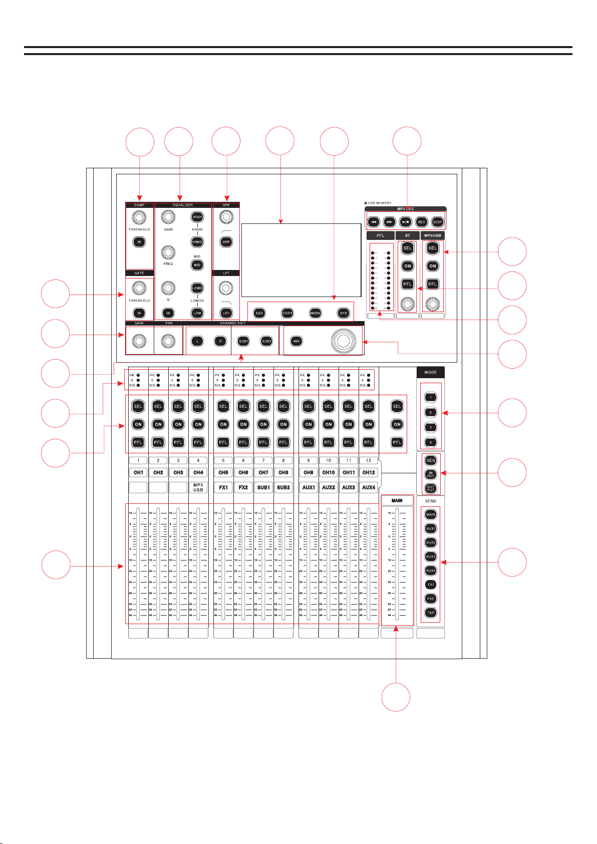
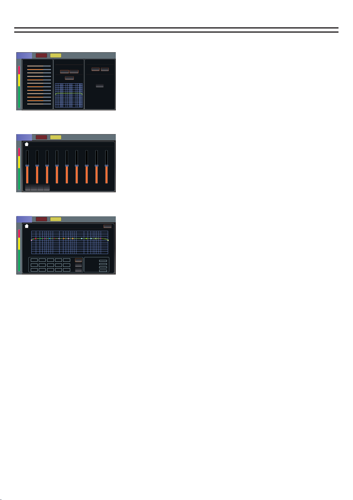
Enter the main page of input channel 1 by default.
Input channel page has noise gate, equalizer, voltage
limiter, send.
1.Gain: Gain/GAIN knob on the panel to control the size.
2.display the current channel signal level.
3. Touch the corresponding function area to enter the
function page.
4. Click to select the parameters to be adjusted, and then
use the multi-function knob to adjust.
5. Click the upper left corner of the function page to return
to the main page of the channel.
Channel main plane
Channel noise page
Channel equalizer page
Channel Limiter page
Channel sending page
1
3
4
20H z
Bwo rth- 12d B
200 00H z
Bwo rth- 12d B
CH1<->CH2 Linked
CH1<->CH2 Linked
CH1<->CH2 Linked
CH1<->CH2 Linked
CH1<->CH2 Linked
5
0.00
DCA
1
5678
234
CLIF
+10
+4
+2
0
-2
-4
-7
-16
-22
-38
-60
1
DCA
5678
234
CLIF
+10
+4
+2
0
-2
-4
-7
-16
-22
-38
-60
1
DCA
5678
234
CLIF
+10
+4
+2
0
-2
-4
-7
-16
-22
-38
-60
1
DCA
5678
234
CLIF
+10
+4
+2
0
-2
-4
-7
-16
-22
-38
-60
1
DCA
5678
234
CLIF
+10
+4
+2
0
-2
-4
-7
-16
-22
-38
-60
F:50 G:50 Q :50 Q
11
PAD
6
2
XY

房间1
用户-1
用户-6
用户-11
用户-16
用户-2
用户-7
用户-12
用户-17
用户-3
用户-8
用户-13
用户-18
用户-4
用户-9
用户-14
用户-19
用户-5
用户-10
用户-15
用户-20
房间2小房间1小房间2大房间 厅堂1厅堂2
混响+延时1混响+延时2混 响+延时3混响+延时4混响+延时5混响+延 时6
双延时+混响1双延 时+混响2双延时+混响3专业 实力 会 议
Preset Mode
Preset Mode
User Mode
User Mode
Close
厅堂3
Load Protect
The effect of channel
Fx1 MUTE PFL
INPUT EQ SEND
HP-TYPE LP-T YPE
ON
Bwo rt h-12 dB Bw or th-1 2dB M AIN
AUX 1
AUX 2
AXU 3
AUX 4
AUX 5/6
Fx1MUTE PFL
INPUT
ON
Wah-Wah
Auto Wah 1
OFF
Distortion
Disto rtion
OFF
Pitch-shif t
Light D etlay
OFF
Reverb/Delay
Small P late
OFF
Mod-FX
choru s
Fx1MUTE PFL
EQ RESET
ON
20k
12
5k 10k
0
6
2k
-6
1k
-12
500200
-18
100
-24
5020
dB:
Fpre:
Q:
Type:
LOW LOW -MID MID HI-MID H I
0.0 dB
80H z 250 Hz 100 0Hz 20 00H z
0.6 0 .6
PEQ PEQ P EQ
0.6 0.6 0 .6
120 00H z
0.0 dB 0.0 dB 0.0 dB 0.0 dB 20H z
Bwo rth- 12d B
200 00H z
Bwo rth- 12d B
PEQ P EQ
HP :
HP-TYPE :
LP :
LP-TYPE :
12 3 45
Fx1MUTE PFL
SEND
-24.0-2 4.0-24.0-2 4.0-24 .0-24.0-24 .0-24.0-24 .0
-24.0
Main
Ch1 Ch2 Ch3 Ch4 Ch5 Ch6 Ch7 Ch8 Ch9
-24.0
AUX1
-24.0
AUX2
-24.0
AUX3/4
-24.0
AUX5/6
-24.0
AUX7/8
-24.0
AUX9/10
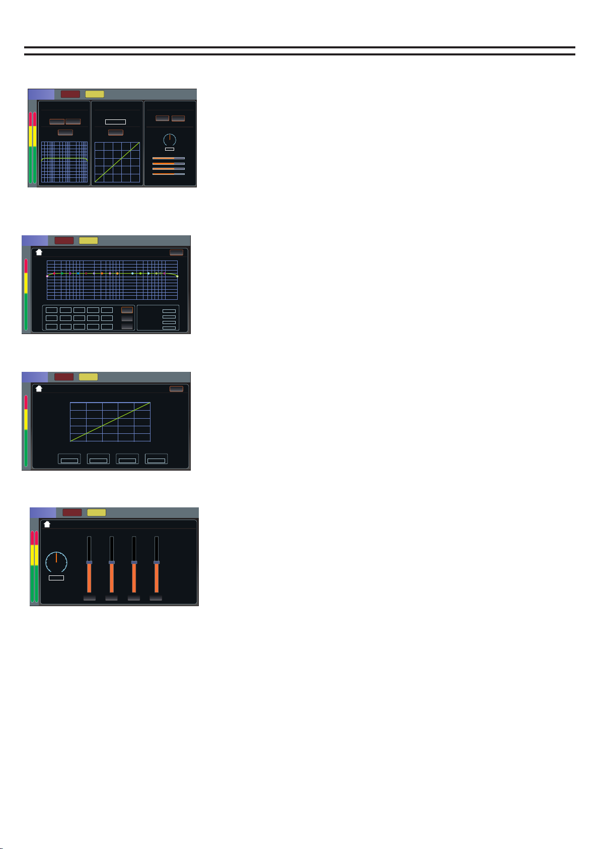
Main page of effect
Effect volume source page
Displays the status of the input channel
sent to the current effect
Effect equalizer page
Effects user effects parameter page
The effect is sent to the output channel page
CH1
CH2
CH3
CH4
CH5
CH6
CH7
CH8
CH9
CH1 0
CH1 1
CH1 2
USER -1
FOOT SW FX1
FOOT SW FX1
FOOT SW FX1
1234
FOOT SW FX1
FOOT SW FX1
SEND
ON
Wah-Wah
Auto Wah 1
OFF
Distortion
Disto rtion
OFF
Pitch-shif t
Light D etlay
OFF
Reverb/Delay
Small P late
OFF
Mod-FX
choru s
RO OM -1
Paramerer
Type
Filter:500Hz
Resonance:50%
Auto Wah:50 %
LPF BPF
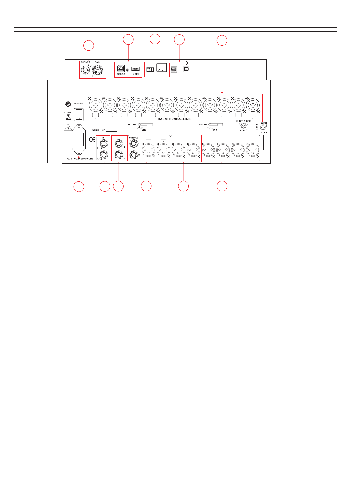
How to enter the effector page.
Find the word "Write (FX) effect channel" on the screen print on
the right output push layer board, and click the SEL button to
turn on FX effect to enter the main page.
Effects channel page has volume source, equalizer, user effects,
send.
1. Touch the corresponding function area to enter the function
page.
2. Click to select the parameters to be adjusted, and then use
the multi-function knob to adjust.
3. Click the homepage icon in the upper left corner to return to
the main page of the channel.
Foot SwitCH
Wah-Wah
Distortion
Pitch-shift
Reverb/Delay
Mod-FX
Effect of name Effect type/value
Fx1 FX2FX1+2
Filter 0Hz-8000Hz
0Hz-8000Hz
0Hz-1200Hz
0Hz-1200Hz 0.02Hz-5.80Hz
-12—+12 0—127
0ms—127ms
0ms—127ms
0—127
0%-100%
0%-100%
0%-100%
0%-100%
0%-100%
0%-100%
0%-100%
0%-100% 0%-100%
0%-200% -22.0dB-+22.0dB
0%-100%
0%-100%
Auto Resonance
Filter Type
1 / 2 Tone
Resonance
Spring
Vibrato
Hall
StepPhaser
Cathedral
Tremolo
Slap-Back
SineChorus
Short-Delay
Phaser
Medium-Delay
Panning
Long-Delay
Flanger
Delay Reverb 1
Choeus
Delay Reverb 1
LevelRev
Level
PreHP
PreHP
Depth Tremshape
PreDelay
DelTime Feedback
TimeRev HDamp
HDamp Rate
Tone
ToneFreq
Type:
Type:
Dry/Wet-Mix
Fine Tune Filter
LPF
BPF
On/off
Type of effect parameter
Effects Mode (Preset Effects Mode and User Effects Mode)
Click Load or Save Effects
1
DCA
5678
234
CLIF
+10
+4
+2
0
-2
-4
-7
-16
-22
-38
-60
1
DCA
5678
234
CLIF
+10
+4
+2
0
-2
-4
-7
-16
-22
-38
-60
1
DCA
5678
234
CLIF
+10
+4
+2
0
-2
-4
-7
-16
-22
-38
-60
1
DCA
5678
234
CLIF
+10
+4
+2
0
-2
-4
-7
-16
-22
-38
-60
F:50 G:50 Q :50 Q
MAI N
AUX 1
AUX 2
AXU 3
AUX 4
AUX 5/6
AUX 7/8
AUX 9/10
12
Marshal the output channels
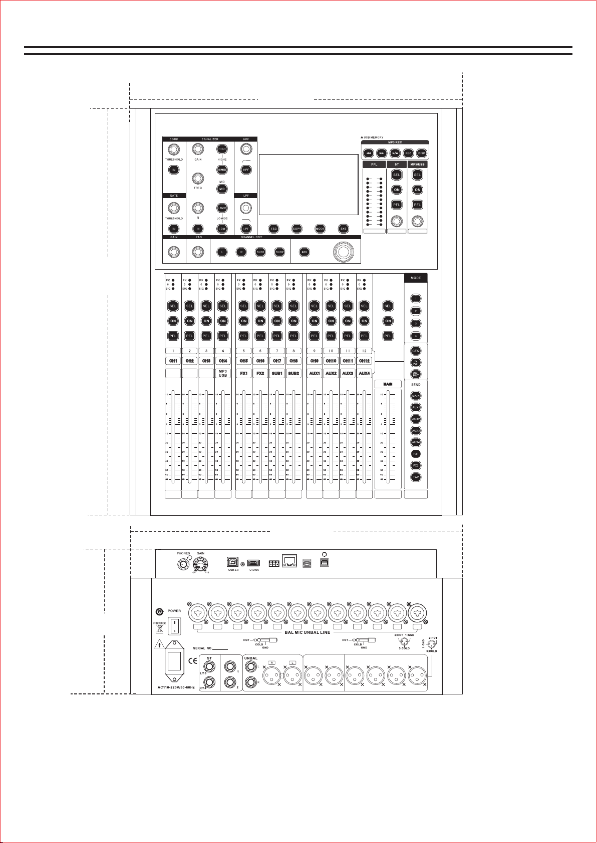
How to enter the marshalling output page.
Press the button "Out" and click to open the output layer
(when it is bright, it means it is already in the output layer).
Find the word "write SUB" grouping on the screen print,
and click the SEL button to open the SUB to enter the
main page.
Effect channel page has equalizer, pressure limiter, send.
1. Touch the corresponding function area to enter the
function page.
2. Click to select the parameters to be adjusted, and then
use the multi-function knob to adjust.
3. Click the homepage icon in the upper left corner to
return to the main page of the channel.
The main page for marshalling output channels
The equalizer page
Pressure limiter page
MUTE PFL
EQ ON
20k
12
5k 10k
0
6
2k
-6
1k
-12
500200
-18
100
-24
5020
20H z
Bwo rth- 12d B
200 00H z
Bwo rth- 12d B
HP :
HP-TYPE :
LP :
LP-TYPE :
1 2 3 4 10
5 7 8 11 13 14
6912 15
SUB1
dB
Fpre
Q
40H z
1
400 Hz
6
400 0Hz
11
63H z
2
630 Hz
7
630 0Hz
12
100 Hz
3
100 0Hz
8
100 00H z
13
160 Hz
4
160 0Hz
9
140 00Hz
14
250 Hz
5
250 0Hz
10
160 00Hz
15
MUTE PFL
COMP ON
0
0
-20
20
20(dB)
-20
-40
-40
-60
-60
-80
(dB)
SUB1
SUB1 MUTE PFL
EQ Send
hp-type lp-type
ON
Bwo rt h-12 dB Bw or th-1 2dB
COMP
-12dB
LEVEL
ON
LR
DELAY
0.0ms
FBX
Phase
OFF
0
0
0.0dB
250 Hz
0.0
13
Level
-135dB
Radio
1.00:1
Hold Time
-135dB
Rel Time
-135dB
Auxiliary output channel
Auxiliary output main page
Sends to the source page of the
secondary output channel
Secondary output equalizer page
MUTE PFL
Input
-24.0-2 4.0-24.0-2 4.0-24 .0-24.0-24 .0-24.0-24 .0
Ch1 Ch2 Ch3 Ch4 Ch5 Ch6 Ch7 Ch8 Ch9
1234
AUX1
MUTE PFL
EQ ON
20k
12
5k 10k
0
6
2k
-6
1k
-12
500200
-18
100
-24
5020
20H z
Bwo rth- 12d B
200 00H z
Bwo rth- 12d B
HP :
HP-TYPE :
LP :
LP-TYPE :
1 2 3 4 10
5 7 8 11 13 14
6912 15
AUX1
dB
Fpre
Q
40H z
1
400 Hz
6
400 0Hz
11
63H z
2
630 Hz
7
630 0Hz
12
100 Hz
3
100 0Hz
8
100 00H z
13
160 Hz
4
160 0Hz
9
140 00H z
14
250 Hz
5
250 0Hz
10
160 00H z
15
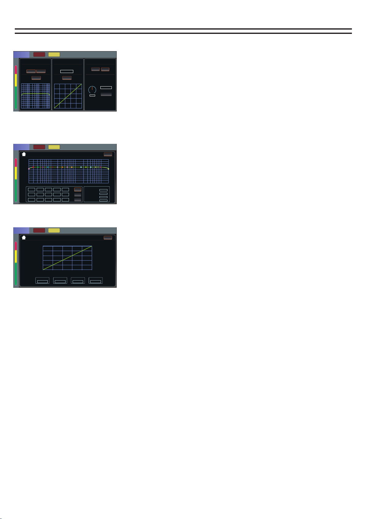
How to enter the secondary output page.
Press the button "Out" to turn over pages, click to
open the output layer (when it is bright, it means you
are already in the output layer), find the words with
AUX assistance on the screen print, and click the SEL
button to open AUX assistance to enter the main
page.
Auxiliary output channel pages are volume source,
equalizer, and send.
1. Touch the corresponding function area to enter the
function page.
2. Click to select the parameters to be adjusted, and
then use the multi-function knob to adjust.
3. Click the homepage icon in the upper left corner to
return to the main page of the channel.
AUX1MUTE PFL
Input
CH1
CH2
CH3
CH4
CH5
CH6
CH7
CH8
CH9
CH1 0
CH1 1
CH1 2
Send
EQ
HP-TYPE LP-T YPE
ON
Bwo rt h-12 dB Bw or th-1 2dB
LR
Phase
0
0
0.0dB
250 Hz
0.0
14
Digital channel
Digital channel home page
The equalizer page
Pressure limiter page
Digital channel signals are routed to the output page
Digital MUTE PFL
EQ SEND
HP-TYPE LP-TYPE
ON
Bwo rt h-12 dB Bw or th-1 2dB
COMP
-12dB
LEVEL
ON
LR
PAN
L=R
MUTE PFL
Send
How to access the digital channel page.
Under Digital In on the right side of the screen, click the
SEL button to open the DIGITAL channel to enter the main
page.
Digital channel page has equalizer, voltage limiter, send.
MP3 and sound card playback control is through the
digital channel to adjust
The upper right corner is the volume display of the digital
channel. The volume can be adjusted by the volume knob
of the digital channel
1. Touch the corresponding function area to enter the
function page.
2. Click to select the parameters to be adjusted, and then
use the multi-function knob to adjust.
3. Click the homepage icon in the upper left corner to
return to the main page of the channel.
A1 Po st
A2 Po st
A3 Po st
A4 Po st
VOLUME -120 .0dB
VO LUME - 120.0dB
-24.0-2 4.0-24.0-2 4.0
PAN
L=R
POSTPOSTPOSTPOST
AUX1 AUX2 AUX3 AUX4
15
MUTE PFL
EQ ON
20k
12
5k 10k
0
6
2k
-6
1k
-12
500200
-18
100
-24
5020
20H z
Bwo rth- 12d B
200 00H z
Bwo rth- 12d B
HP :
HP-TYPE :
LP :
LP-TYPE :
1 2 3 4 10
5 7 8 11 13 14
6912 15
Digital
dB
Fpre
Q
40H z
1
400 Hz
6
400 0Hz
11
63H z
2
630 Hz
7
630 0Hz
12
100 Hz
3
100 0Hz
8
100 00H z
13
160 Hz
4
160 0Hz
9
140 00Hz
14
250 Hz
5
250 0Hz
10
160 00Hz
15
0.0dB
250 Hz
0.0
VOLUME -120 .0dB
MUTE PFL
COMP ON
0
0
-20
20
20(dB)
-20
-40
-40
-60
-60
-80
(dB)
Level
-135dB
Radio
1.00:1
Hold Time
-135dB
Rel Time
-135dB
VOLUME -120 .0dB
Digital
Digital

System Settings
Mp3/ sound card playback and recording
1. About the machine: here you can view the machine model, firmware version number, application
version number, serial number of information.
2. Network: You can change the network IP address here.
3. Custom layer: set the custom channel in the custom layer, and then press the INPUT/OUTPUT button
together to enable the function of the custom layer.
4. Language: Here to modify the language, the machine supports Chinese language and English language.
5. Update: Software can be updated here.
Download the update software to the USB flash drive, then plug the USB flash drive into the mixer, click
the button to open the update, it will automatically recognize that the software will automatically update,
you need to wait.
6. Restore factory Settings: one key can be pressed to restore the machine parameters to the original
factory Settings.
System setting
Network
Language
Custom Layer
Factory Reset
About
Software Update
V:T16-1.6.7
Press the SYS button to enter the system setting page
How to access the MP3 page:
1. Press the DISP button in the MP3 operation area to enter the MP3 page.
2. Plug in the U disk with the song, and the U disk will be automatically identified.So that the song is displayed.
Learn about MP3 pages:
1. The directory area can be swiped up and down to turn pages.
2. This area is Last, Pause/Play, Next, Random/Single Loop/Sequence.
3. Start recording and pause recording, recording will automatically appear the name of the recording file,
recording is REC button will keep flashing.
4. The total pause (can pause the playback or recording pause), song positioning, song deletion.
Play page
USB STICK Item
Lyrics 00.012132
File 1.4441131
File 2.454564564
File 3.46274646
File 4.79134
File 5.248643
File 6.156876216348
00:00
234
16
last song The next song
Play/Pause
The recording
Enter the page button
Note:
When recording, the recording signal is the main output signal, so the recording must ensure that the main
output signal output is normal, otherwise it will not record the sound
Sound card recording needs to be connected to the computer through the USB cable, open the recording
software on the computer, select the sound card of the mixer,MP3 recording directly to the U disk inside.

Load/save mode
Local page
Load / Save Mode USB Disk
U disk page
SAVE MODE LOAD MODE
File 1.154141
File 2.155341
File 3.152214
File 4.535431
File 5.1512.351
File 6.1124458
File 7.15653
How to use load and save
The following loading and saving pages are local and U disk pages respectively.
How to save user data:
1. Set parameter data such as input, output and effect, and click Open Mode button.
2. There are altogether 20 scenes for the user to save. Click the scene number to be saved, and then press the
"Save Mode" button.
How to load user data:
1. Go to the Loading/Preservation page, select the user to be loaded, and then click the "Loading Mode" button.
2.There are 4 buttons in the MODE area of the control panel, where you can quickly call up the first 4 users of user
data, and then press "OK" on the screen
Complete the call up of user data.
User's USB disk data:
1. Set the input, output, effect and other parameters, to load and save the page, click the U disk symbol in the
lower left corner to enter the U disk page (orange indicates there is a U disk
Insert).
2. Press the save key, write the name after the completion of the virtual keyboard ENTE (Enter key), and then press
the confirm key can be saved to the U disk.
3. Insert U disk will automatically identify. Load the user data from the U disk, and the blue area is to select the
current user data. After selecting it, press the Load button, and then you can confirm it
To load user data to the current channel.
Channel replication page
COPY TO
Ch1
Ch9
Ch2
Ch10
Ch3
Ch11
Ch4
Ch12
Ch5 Ch6
Ch7 Ch8
1. Set parameter data such as input, output and effect in the current channel, and then click Open Copy to enter
the COPY page.
2. Select the channel and click the Copy button to complete the COPY.
SAVE/LOAD
SAVE MODE Load mode
1
2
3
4
5
6
7
8
9
10
11
12
13
14
15
16
17
18
19
20
17
This manual suits for next models
1
Table of contents
Popular Music Mixer manuals by other brands


Audio Technica
Audio Technica AT-DMM828 installation instructions

Radio Shack
Radio Shack 4-CHANNEL STEREO SSM-1750 owner's manual

Air Comm Systems
Air Comm Systems ACS 775SL-100 Installation and operation manual

SoundCraft
SoundCraft BVE100 user guide

sescom
sescom SES-DSLR-PROMIX user manual

Behringer
Behringer XENYX QX1204USB quick start guide


