EUROPOLE ALIMENTATION SMART 4 in 1 User manual
1
EUROPOLE - 19, avenue ZAC de Chassagne - 69360 TERNAY - Fax : +33 (0)4 72 24 73 42 - www.europole.net
Digita l display
AC power /
Tria c signal input
1 chane l LED outpu t
DALI/AC push intput
0-60 -9
SEC :
Outpu t Voltage=24VDC
Irated=8.3A max
Prated=200 W max
INPU T:
220-240V~ 1A 50/60Hz
NC=None connec t Suitable for Dam p Location s (CONVIEN T AUX EMPLACEMENTS HUMIDES )
>0.95@230V AC
90
45
LED OUTP UT
L
N
AC INPU T
FG
DA
DA
DALI I NPUT
NC
NC
NC
PUSH DIM
L
N
DA
DA
NC
NC
0/1 -10V
GND 0/1-10V signa l input
ALIMENTATION SMART 4 in 1 - 24 VDC
AVERTISSEMENT : L’installation doit être réalisée par des personnes qualifiées en respectant les normes et réglementations en vigueur. Il est rappelé que la décision d’installation des produits dans un environnement compatible et conforme aux normes et règles de l’art, est de la responsabilité pleine
et entière de l’acheteur et de l’installateur. Lisez et respectez les instructions avant d’installer, de mettre sous tension ou d’utiliser les produits. Nous déclinons toute responsabilité résultant d’une mise en œuvre ou d’une installation inappropriée des produits.
Les appareils ne doivent pas être modifiés, même partiellement, faute de quoi la garantie ne pourra s’appliquer.
IMPORTANT : Toujours couper le courant au niveau du réseau avant chaque opération d’installation ou de maintenance.
1. SPÉCIFICATIONS TECHNIQUES
Sortie
Sortie commande LED 1 (avec 2 groupes de sortie en parallèle)
Tension constante 24V DC
Courant Max Max 4,16A/groupe de sortie (groupe1+groupe2 =
8,32A)
Tolerance de tension ± 1%
Puissance max 200W
Entrée
Plage de tension 220-240V AC
Plage de fréquence 50/60Hz
Facteur de puissance >0,95@230VAC
Distorsion harmonique totale THD⩽15% (@chargé / 230VAC)
Rendement 93% @ 230VAC chargé
Courant AC 1A @ 230VAC
Pic de courant 65A @230VAC
Courant de fuite < 0,5mA/230VAC
Variation
Interface de variation DALI/Bouton+Triac+0/1-10V
Plage de variation 0,1%-100%
Méthode de variation Modulation de largeur d’impulsion
Protection
Court circuit Oui, rétablissement automatique après la fin du
défaut
Surintensité Oui, rétablissement automatique après la fin du
défaut
Surchauffe Oui, rétablissement automatique après la fin du
défaut
2. SCHÉMA DE CÂBLAGE
TRIAC
FR
Sortie commande LED
Sortie signal 0/1-10V
Ecran digital
Entrée Commande
DALI/AC
Alimentation AC /
Entrée signal Triac
Environ-
nement
Température de fonctionnement -25°C ~ +45°C
Température max du boitier 90°C
Humidité de fonctionnement 10%~ 95% Humidité relative
Température de stockage et
humidité -40°C ~ +80°C, 10%~ 95% HR
Sécurité et
CEM
Standard de sécurité EN61347-1,EN61347-3-13 approuvé
Tension de tenu I/P-O/P:3,75KVAC
Résistance d’isolement I/P-O/P:100M Ohms / 500VDC / 25°C / 70% HR
Emission CEM EN61347-1, EN61000-3-2,EN6111-3-3
Immunité CEM EN61547,EN61000-4-2,3,4,5,6,8,11, immunité
surtention ligne-ligne 1kV
Autre
Temps moyen entre panne 193,6k Heures minimum @230VAC chargé et 25°C
Dimensions 240*72*36mm(L*l*H)
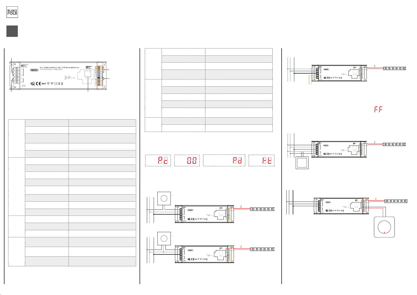
1. 4 possibilités de variation : DALI, Bouton poussoir, Triac, 0/1-10V
2. N’utiliser qu’une seule solution de variation à la fois
3. L’écran affichera automatiquement un code correspondant à la solution de variation câblée
sur le produit :
Note: DALI address can be manually assigned from 00-63-FF, by factory defaults, no DALI
address is assigned for the driver, and the display shows . Setting DALI address as
will reset the dimmer to factory defaults.
3.1 DALI address can also be assigned by DALI Master controller automatically, please refer to user manuals of
compatible DALI Masters for specific operations.
Note: The digital display will show when the DALI master is assigning addresses.
3. DALI Address Assigned by DALI Masters
4.PUSH Dimmer Mode
While connected with a AC push switch, the digital display will show “PD” which means Push Dimmer
Mode, operations under PUSH Mode are as follows:
4.1. Click the button to switch ON/OFF
4.2. Press and hold down the button to increase or decrease light intensity to desired level and release it, then
repeat the operation to adjust light intensity to opposite direction. The dimming range is from 1% to 100%.
4.3. Memory function after power off or power failure enables the device to memorize the status before power
off while power on again.
2.1 Press and hold down any of the two buttons until numeric digital display flashes, then release
the button.
2.2 Click any of the two buttons once to select a digit, click again to change the digit until the
desired DALI address appears. Click first button to set “tens” position and second button to set
“units” position. The address can be set from 00~63.
2.3 Then press and hold down any of the 2 buttons until the numeric digital display stops flashing
to confirm the setting.
0-6 0-9
2. Set DALI Address Manually While Connected with DALI Input
While connected with a Triac dimmer, different Triac dimmers from different suppliers may have different
minimum dimming levels which the driver can not be dimmed below. To dim to 1%, please make sure the
dimmer supports 1% minimum dimming level.
5. Triac Dimming Input
240.00 mm
72.00 mm 36.00 m m
Product Dimension
0-6 0-9
Wiring diagram
1.With DALI bus
2.With PUSH dimmer
3.With Triac Dimmer
4.With 0/1-10V dimmer
(AWG18-10 )
(0.55-0.86in)
(AWG20-14 )
(0.24-0.28in)
Tria c & DALI & AC Pu sh & 0/1- 10V Dim mable D river
SEC:
Output Voltage=24VDC
Irated=8.3A max
Pout=200W max
INPUT:
220-240V~ 1A 50/60Hz
LED CL ASS 1 (CL ASSE 1) P OWER SU PPLY
ta
λ>0.95@230VAC:
90
45
L
N
AC INPUT
LED OUTPUT
FG
NC
DA
DA
DALI INP UT
PUSH DI M
L
N
DA
DA
NC
NC
NC=None connect Suitable for Damp Locations (CONVIENT AUX EMPLACEMENTS HUMIDES)
NC
NC
0/1-10V
GND
0-6 0-9
L N GND
DALI bus
LED light
(AWG18-10 )
(0.55-0.86in)
(AWG20-14 )
(0.24-0.28in)
Tria c & DALI & AC Pu sh & 0/1- 10V Dim mable D river
SEC:
Output Voltage=24VDC
Irated=8.3A max
Pout=200W max
INPUT:
220-240V~ 1A 50/60Hz
LED CL ASS 1 (CL ASSE 1) P OWER SU PPLY
ta
λ>0.95@230VAC:
90
45
L
N
AC INPUT
LED OUTPUT
FG
NC
DA
DA
DALI INP UT
PUSH DI M
L
N
DA
DA
NC
NC
NC=None connect Suitable for Damp Locations (CONVIENT AUX EMPLACEMENTS HUMIDES)
NC
NC
0/1-10V
GND
0-6 0-9
L N GND
AC PUS H
(AWG18-10 )
(0.55-0.86in)
(AWG20-14 )
(0.24-0.28in)
Tria c & DALI & AC Pu sh & 0/1- 10V Dim mable D river
SEC:
Output Voltage=24VDC
Irated=8.3A max
Pout=200W max
INPUT:
220-240V~ 1A 50/60Hz
LED CL ASS 1 (CL ASSE 1) P OWER SU PPLY
ta
λ>0.95@230VAC:
90
45
L
N
AC INPUT
LED OUTPUT
FG
NC
DA
DA
DALI INP UT
PUSH DI M
L
N
DA
DA
NC
NC
NC=None connect Suitable for Damp Locations (CONVIENT AUX EMPLACEMENTS HUMIDES)
NC
NC
0/1-10V
GND
0-6 0-9
L N GND Triac dimmer (No Neutral Wire)
(AWG18-10 )
(0.55-0.86in)
(AWG20-14 )
(0.24-0.28in)
Tria c & DALI & AC Pu sh & 0/1- 10V Dim mable D river
SEC:
Output Voltage=24VDC
Irated=8.3A max
Pout=200W max
INPUT:
220-240V~ 1A 50/60Hz
LED CL ASS 1 (CL ASSE 1) P OWER SU PPLY
ta
λ>0.95@230VAC:
90
45
L
N
AC INPUT
LED OUTPUT
FG
NC
DA
DA
DALI INPUT
PUSH DI M
L
N
DA
DA
NC
NC
NC=None connect Suitable for Damp Locations (CONVIENT AUX EMPLACEMENTS HUMIDES)
NC
NC
0/1-10V
GND
0-6 0-9
L N GND
0/1-10V
Control Unit
V+ V+
V- V-
LED light
V+ V+
V- V-
LED light
V+ V+
V- V-
(AWG18-10 )
(0.55-0.86in)
(AWG20-14 )
(0.24-0.28in)
Tria c & DALI & AC Pu sh & 0/1- 10V Dim mable D river
SEC:
Output Voltage=24VDC
Irated=8.3A max
Pout=200W max
INPUT:
220-240V~ 1A 50/60Hz
LED CL ASS 1 (CL ASSE 1) P OWER SU PPLY
ta
λ>0.95@230VAC:
90
45
L
N
AC INPUT
LED OUTPUT
FG
NC
DA
DA
DALI INPUT
PUSH DI M
L
N
DA
DA
NC
NC
NC=None connect Suitable for Damp Locations (CONVIENT AUX EMPLACEMENTS HUMIDES)
NC
NC
0/1-10V
GND
0-6 0-9
L N GND Triac dimmer (With Neutral Wire)
LED light
V+ V+
V- V-
LED light
V+ V+
V- V-
Note: DALI address can be manually assigned from 00-63-FF, by factory defaults, no DALI
address is assigned for the driver, and the display shows . Setting DALI address as
will reset the dimmer to factory defaults.
3.1 DALI address can also be assigned by DALI Master controller automatically, please refer to user manuals of
compatible DALI Masters for specific operations.
Note: The digital display will show when the DALI master is assigning addresses.
3. DALI Address Assigned by DALI Masters
4.PUSH Dimmer Mode
While connected with a AC push switch, the digital display will show “PD” which means Push Dimmer
Mode, operations under PUSH Mode are as follows:
4.1. Click the button to switch ON/OFF
4.2. Press and hold down the button to increase or decrease light intensity to desired level and release it, then
repeat the operation to adjust light intensity to opposite direction. The dimming range is from 1% to 100%.
4.3. Memory function after power off or power failure enables the device to memorize the status before power
off while power on again.
2.1 Press and hold down any of the two buttons until numeric digital display flashes, then release
the button.
2.2 Click any of the two buttons once to select a digit, click again to change the digit until the
desired DALI address appears. Click first button to set “tens” position and second button to set
“units” position. The address can be set from 00~63.
2.3 Then press and hold down any of the 2 buttons until the numeric digital display stops flashing
to confirm the setting.
0-6 0-9
2. Set DALI Address Manually While Connected with DALI Input
While connected with a Triac dimmer, different Triac dimmers from different suppliers may have different
minimum dimming levels which the driver can not be dimmed below. To dim to 1%, please make sure the
dimmer supports 1% minimum dimming level.
5. Triac Dimming Input
240.0 0 mm
72.00 m m 36.00 m m
Product Dimension
0-6 0-9
Wiring diagram
1.With DALI bus
2.With PUSH dimmer
3.With Triac Dimmer
4.With 0/1-10V dimmer
(AWG18-10 )
(0.55-0.86in)
(AWG20-14 )
(0.24-0.28in)
Tria c & DALI & AC Pu sh & 0/1- 10V Dim mable D river
SEC:
Output Voltage=24VDC
Irated=8.3A max
Pout=200W max
INPUT:
220-240V~ 1A 50/60Hz
LED CL ASS 1 (CL ASSE 1) P OWER SU PPLY
ta
λ>0.95@230VAC:
90
45
L
N
AC INPUT
LED OUTPUT
FG
NC
DA
DA
DALI INP UT
PUSH DIM
L
N
DA
DA
NC
NC
NC=None connect Suitable for Damp Locations (CONVIENT AUX EMPLACEMENTS HUMIDES)
NC
NC
0/1-10V
GND
0-6 0-9
L N GND
DALI bu s
LED light
(AWG18-10 )
(0.55-0.86in)
(AWG20-14 )
(0.24-0.28in)
Tria c & DALI & AC Pu sh & 0/1- 10V Dim mable D river
SEC:
Output Voltage=24VDC
Irated=8.3A max
Pout=200W max
INPUT:
220-240V~ 1A 50/60Hz
LED CL ASS 1 (CL ASSE 1) P OWER SU PPLY
ta
λ>0.95@230VAC:
90
45
L
N
AC INPUT
LED OUTPUT
FG
NC
DA
DA
DALI INP UT
PUSH DIM
L
N
DA
DA
NC
NC
NC=None connect Suitable for Damp Locations (CONVIENT AUX EMPLACEMENTS HUMIDES)
NC
NC
0/1-10V
GND
0-6 0-9
L N GND
AC PUSH
(AWG18-10 )
(0.55-0.86in)
(AWG20-14 )
(0.24-0.28in)
Tria c & DALI & AC Pu sh & 0/1- 10V Dim mable D river
SEC:
Output Voltage=24VDC
Irated=8.3A max
Pout=200W max
INPUT:
220-240V~ 1A 50/60Hz
LED CL ASS 1 (CL ASSE 1) P OWER SU PPLY
ta
λ>0.95@230VAC:
90
45
L
N
AC INPUT
LED OUTPUT
FG
NC
DA
DA
DALI INP UT
PUSH DIM
L
N
DA
DA
NC
NC
NC=None connect Suitable for Damp Locations (CONVIENT AUX EMPLACEMENTS HUMIDES)
NC
NC
0/1-10V
GND
0-6 0-9
L N GND Triac dimmer (No Neutral Wire)
(AWG18-10 )
(0.55-0.86in)
(AWG20-14 )
(0.24-0.28in)
Tria c & DALI & AC Pu sh & 0/1- 10V Dim mable D river
SEC:
Output Voltage=24VDC
Irated=8.3A max
Pout=200W max
INPUT:
220-240V~ 1A 50/60Hz
LED CL ASS 1 (CL ASSE 1) P OWER SU PPLY
ta
λ>0.95@230VAC:
90
45
L
N
AC INPUT
LED OUTPUT
FG
NC
DA
DA
DALI INPUT
PUSH DIM
L
N
DA
DA
NC
NC
NC=None connect Suitable for Damp Locations (CONVIENT AUX EMPLACEMENTS HUMIDES)
NC
NC
0/1-10V
GND
0-6 0-9
L N GND
0/1-10V
Control Unit
V+ V+
V- V-
LED light
V+ V+
V- V-
LED light
V+ V+
V- V-
(AWG18-10 )
(0.55-0.86in)
(AWG20-14 )
(0.24-0.28in)
Tria c & DALI & AC Pu sh & 0/1- 10V Dim mable D river
SEC:
Output Voltage=24VDC
Irated=8.3A max
Pout=200W max
INPUT:
220-240V~ 1A 50/60Hz
LED CL ASS 1 (CL ASSE 1) P OWER SU PPLY
ta
λ>0.95@230VAC:
90
45
L
N
AC INPUT
LED OUTPUT
FG
NC
DA
DA
DALI INPUT
PUSH DIM
L
N
DA
DA
NC
NC
NC=None connect Suitable for Damp Locations (CONVIENT AUX EMPLACEMENTS HUMIDES)
NC
NC
0/1-10V
GND
0-6 0-9
L N GND Triac dimmer (With Neutral Wire)
LED light
V+ V+
V- V-
LED light
V+ V+
V- V-
DALI
BOUTON POUSSOIR
BOUTON POUSSOIR 0/1-10V
Modifier l’adresse DALI lorsque que le produit est contrôlé par un bus DALI :
- Appuyer sur l’un des 2 boutons jusqu’à ce que l’écran digital clignote
- Appuyer sur le bouton sous le chiffre à modifier, l’adresse dois être comprise entre 00 et 63
- Appuyer sur l’un des 2 boutons jusqu’à ce que l’écran digital arrête de clignoter
Note : Par défaut le contrôleur n’a pas d’adresse assigné. Assigner remet le contrôleur aux
paramètres d’usine.
Variateur Triac (sans fil neutre)
Variateur Triac (avec fil neutre)
Variateur
0/1-10V
NOTICE D’UTILISATION MULTILINGUE EUROPOLE - n°246 - V1 - 02/05/2019 - ALIMENTATION SMART 4 in 1 - 24 VDC
TRIAC DALI Bouton poussoir
(Push dim) 1-10V

2
EUROPOLE - 19, avenue ZAC de Chassagne - 69360 TERNAY - Fax : +33 (0)4 72 24 73 42 - www.europole.net
EN
ALIMENTATION SMART 4 in 1 - 24 VDC
Digita l display
AC power /
Tria c signal input
1 chane l LED outpu t
DALI/AC push intput
0-60 -9
SEC :
Outpu t Voltage=24VDC
Irated=8.3A max
Prated=200 W ma x
INPU T:
220-240V~ 1A 50/60Hz
NC=None c onnec t S uitable for D am p Location s (CONVIEN T AU X EMPLACEMENTS HUMIDES )
>0.95@230V AC
90
45
LED OUTP UT
L
N
AC INPU T
FG
DA
DA
DALI I NPUT
NC
NC
NC
PUSH DIM
L
N
DA
DA
NC
NC
0/1 -10V
GND 0/1-10V signa l input
WARNING: The installation must be carried out by qualified persons in accordance with the standards and regulations in force. It is recalled that the decision to install the products in an environment compatible and in compliance with the standards and good practices is the full responsibility of the
buyer and the installer. Read and follow the instructions before installing, powering on or using the products. We do not accept any liability resulting from improper implementation or installation of the products.
The devices must not be modified, even partially, otherwise the warranty will not apply.
IMPORTANT: Always turn off the power to the network before each installation or maintenance operation.
1. TECHNICAL SPECIFICATIONS
Outlet
LED control outlet 1 (with 2 parallel outlet units)
Constant voltage 24V DC
Maximum current Max. 4.16A/outlet unit (unit1+unit2 = 8.32A)
Voltage tolerance ± 1%
Power max. 200W
Inlet
Voltage range 220-240V AC
Frequency range 50/60Hz
Power factor >0,95@230VAC
Total harmonic distortion THD⩽15% (@charged / 230VAC)
Output 93% @ 230VAC charged
AC current 1A @ 230VAC
Current peak 65A @230VAC
Leakage current < 0,5mA/230VAC
Variation
Variation interface DALI/Button+Triac+0/1-10V
Variation range 0,1%-100%
Variation method Pulse width modulation
Protection
Short circuit Yes, automatic re-establishment once defect is
resolved
Over-intensity Yes, automatic re-establishment once defect is
resolved
Over-heating Yes, automatic re-establishment once defect is
resolved
2. CABLING DIAGRAM
TRIAC
LED control outlet
0/1-10V signal outlet
Digital screen
DALI/AC control
inlet
AC power supply /
Triac signal inlet
Environ-
ment
Operating temperatures -25°C ~ +45°C
Max. casing temperature 90°C
Operating humidity 10%~ 95% relative humidity
Storage temperature and
humidity -40°C ~ +80°C, 10%~ 95% HR
Security
and EMC
(electro-
magnetic
compatibi-
lity)
Security standard EN61347-1, EN61347-3-13 approved
Withstand voltage I/P-O/P:3,75KVAC
Insulation resistance I/P-O/P:100M Ohms / 500VDC / 25°C / 70%
Relative Humidity
EMC emission EN61347-1, EN61000-3-2,EN6111-3-3
EMC immunity EN61547,EN61000-4-2,3,4,5,6,8,11, 1kV line-line
surge immunity
Other
Average time between malfu-
nctions
193.6k hours minimum @230VAC charged and
25°C
Dimensions 240*72*36mm(L*l*H)
1. Four possible variations: DALI, push button, Triac, 0/1-10V
2. Use just one variation solution at a time
3. The screen will automatically display a code corresponding to the cabled variation solution on the
product:
Note: DALI address can be manually assigned from 00-63-FF, by factory defaults, no DALI
address is assigned for the driver, and the display shows . Setting DALI address as
will reset the dimmer to factory defaults.
3.1 DALI address can also be assigned by DALI Master controller automatically, please refer to user manuals of
compatible DALI Masters for specific operations.
Note: The digital display will show when the DALI master is assigning addresses.
3. DALI Address Assigned by DALI Masters
4.PUSH Dimmer Mode
While connected with a AC push switch, the digital display will show “PD” which means Push Dimmer
Mode, operations under PUSH Mode are as follows:
4.1. Click the button to switch ON/OFF
4.2. Press and hold down the button to increase or decrease light intensity to desired level and release it, then
repeat the operation to adjust light intensity to opposite direction. The dimming range is from 1% to 100%.
4.3. Memory function after power off or power failure enables the device to memorize the status before power
off while power on again.
2.1 Press and hold down any of the two buttons until numeric digital display flashes, then release
the button.
2.2 Click any of the two buttons once to select a digit, click again to change the digit until the
desired DALI address appears. Click first button to set “tens” position and second button to set
“units” position. The address can be set from 00~63.
2.3 Then press and hold down any of the 2 buttons until the numeric digital display stops flashing
to confirm the setting.
0-6 0-9
2. Set DALI Address Manually While Connected with DALI Input
While connected with a Triac dimmer, different Triac dimmers from different suppliers may have different
minimum dimming levels which the driver can not be dimmed below. To dim to 1%, please make sure the
dimmer supports 1% minimum dimming level.
5. Triac Dimming Input
240.00 mm
72.00 mm 36.00 m m
Product Dimension
0-6 0-9
Wiring diagram
1.With DALI bus
2.With PUSH dimmer
3.With Triac Dimmer
4.With 0/1-10V dimmer
(AWG18-10 )
(0.55-0.86in)
(AWG20-14 )
(0.24-0.28in)
Tria c & DALI & AC Pu sh & 0/1- 10V Dim mable D river
SEC:
Output Voltage=24VDC
Irated=8.3A max
Pout=200W max
INPUT:
220-240V~ 1A 50/60Hz
LED CL ASS 1 (CL ASSE 1) P OWER SU PPLY
ta
λ>0.95@230VAC:
90
45
L
N
AC INPUT
LED OUTPUT
FG
NC
DA
DA
DALI INP UT
PUSH DI M
L
N
DA
DA
NC
NC
NC=None connect Suitable for Damp Locations (CONVIENT AUX EMPLACEMENTS HUMIDES)
NC
NC
0/1-10V
GND
0-6 0-9
L N GND
DALI bus
LED light
(AWG18-10 )
(0.55-0.86in)
(AWG20-14 )
(0.24-0.28in)
Tria c & DALI & AC Pu sh & 0/1- 10V Dim mable D river
SEC:
Output Voltage=24VDC
Irated=8.3A max
Pout=200W max
INPUT:
220-240V~ 1A 50/60Hz
LED CL ASS 1 (CL ASSE 1) P OWER SU PPLY
ta
λ>0.95@230VAC:
90
45
L
N
AC INPUT
LED OUTPUT
FG
NC
DA
DA
DALI INP UT
PUSH DI M
L
N
DA
DA
NC
NC
NC=None connect Suitable for Damp Locations (CONVIENT AUX EMPLACEMENTS HUMIDES)
NC
NC
0/1-10V
GND
0-6 0-9
L N GND
AC PUS H
(AWG18-10 )
(0.55-0.86in)
(AWG20-14 )
(0.24-0.28in)
Tria c & DALI & AC Pu sh & 0/1- 10V Dim mable D river
SEC:
Output Voltage=24VDC
Irated=8.3A max
Pout=200W max
INPUT:
220-240V~ 1A 50/60Hz
LED CL ASS 1 (CL ASSE 1) P OWER SU PPLY
ta
λ>0.95@230VAC:
90
45
L
N
AC INPUT
LED OUTPUT
FG
NC
DA
DA
DALI INP UT
PUSH DI M
L
N
DA
DA
NC
NC
NC=None connect Suitable for Damp Locations (CONVIENT AUX EMPLACEMENTS HUMIDES)
NC
NC
0/1-10V
GND
0-6 0-9
L N GND Triac dimmer (No Neutral Wire)
(AWG18-10 )
(0.55-0.86in)
(AWG20-14 )
(0.24-0.28in)
Tria c & DALI & AC Pu sh & 0/1- 10V Dim mable D river
SEC:
Output Voltage=24VDC
Irated=8.3A max
Pout=200W max
INPUT:
220-240V~ 1A 50/60Hz
LED CL ASS 1 (CL ASSE 1) P OWER SU PPLY
ta
λ>0.95@230VAC:
90
45
L
N
AC INPUT
LED OUTPUT
FG
NC
DA
DA
DALI INPUT
PUSH DI M
L
N
DA
DA
NC
NC
NC=None connect Suitable for Damp Locations (CONVIENT AUX EMPLACEMENTS HUMIDES)
NC
NC
0/1-10V
GND
0-6 0-9
L N GND
0/1-10V
Control Unit
V+ V+
V- V-
LED light
V+ V+
V- V-
LED light
V+ V+
V- V-
(AWG18-10 )
(0.55-0.86in)
(AWG20-14 )
(0.24-0.28in)
Tria c & DALI & AC Pu sh & 0/1- 10V Dim mable D river
SEC:
Output Voltage=24VDC
Irated=8.3A max
Pout=200W max
INPUT:
220-240V~ 1A 50/60Hz
LED CL ASS 1 (CL ASSE 1) P OWER SU PPLY
ta
λ>0.95@230VAC:
90
45
L
N
AC INPUT
LED OUTPUT
FG
NC
DA
DA
DALI INPUT
PUSH DI M
L
N
DA
DA
NC
NC
NC=None connect Suitable for Damp Locations (CONVIENT AUX EMPLACEMENTS HUMIDES)
NC
NC
0/1-10V
GND
0-6 0-9
L N GND Triac dimmer (With Neutral Wire)
LED light
V+ V+
V- V-
LED light
V+ V+
V- V-
Note: DALI address can be manually assigned from 00-63-FF, by factory defaults, no DALI
address is assigned for the driver, and the display shows . Setting DALI address as
will reset the dimmer to factory defaults.
3.1 DALI address can also be assigned by DALI Master controller automatically, please refer to user manuals of
compatible DALI Masters for specific operations.
Note: The digital display will show when the DALI master is assigning addresses.
3. DALI Address Assigned by DALI Masters
4.PUSH Dimmer Mode
While connected with a AC push switch, the digital display will show “PD” which means Push Dimmer
Mode, operations under PUSH Mode are as follows:
4.1. Click the button to switch ON/OFF
4.2. Press and hold down the button to increase or decrease light intensity to desired level and release it, then
repeat the operation to adjust light intensity to opposite direction. The dimming range is from 1% to 100%.
4.3. Memory function after power off or power failure enables the device to memorize the status before power
off while power on again.
2.1 Press and hold down any of the two buttons until numeric digital display flashes, then release
the button.
2.2 Click any of the two buttons once to select a digit, click again to change the digit until the
desired DALI address appears. Click first button to set “tens” position and second button to set
“units” position. The address can be set from 00~63.
2.3 Then press and hold down any of the 2 buttons until the numeric digital display stops flashing
to confirm the setting.
0-6 0-9
2. Set DALI Address Manually While Connected with DALI Input
While connected with a Triac dimmer, different Triac dimmers from different suppliers may have different
minimum dimming levels which the driver can not be dimmed below. To dim to 1%, please make sure the
dimmer supports 1% minimum dimming level.
5. Triac Dimming Input
240.0 0 mm
72.00 m m 36.00 m m
Product Dimension
0-6 0-9
Wiring diagram
1.With DALI bus
2.With PUSH dimmer
3.With Triac Dimmer
4.With 0/1-10V dimmer
(AWG18-10 )
(0.55-0.86in)
(AWG20-14 )
(0.24-0.28in)
Tria c & DALI & AC Pu sh & 0/1- 10V Dim mable D river
SEC:
Output Voltage=24VDC
Irated=8.3A max
Pout=200W max
INPUT:
220-240V~ 1A 50/60Hz
LED CL ASS 1 (CL ASSE 1) P OWER SU PPLY
ta
λ>0.95@230VAC:
90
45
L
N
AC INPUT
LED OUTPUT
FG
NC
DA
DA
DALI INP UT
PUSH DIM
L
N
DA
DA
NC
NC
NC=None connect Suitable for Damp Locations (CONVIENT AUX EMPLACEMENTS HUMIDES)
NC
NC
0/1-10V
GND
0-6 0-9
L N GND
DALI bu s
LED light
(AWG18-10 )
(0.55-0.86in)
(AWG20-14 )
(0.24-0.28in)
Tria c & DALI & AC Pu sh & 0/1- 10V Dim mable D river
SEC:
Output Voltage=24VDC
Irated=8.3A max
Pout=200W max
INPUT:
220-240V~ 1A 50/60Hz
LED CL ASS 1 (CL ASSE 1) P OWER SU PPLY
ta
λ>0.95@230VAC:
90
45
L
N
AC INPUT
LED OUTPUT
FG
NC
DA
DA
DALI INP UT
PUSH DIM
L
N
DA
DA
NC
NC
NC=None connect Suitable for Damp Locations (CONVIENT AUX EMPLACEMENTS HUMIDES)
NC
NC
0/1-10V
GND
0-6 0-9
L N GND
AC PUSH
(AWG18-10 )
(0.55-0.86in)
(AWG20-14 )
(0.24-0.28in)
Tria c & DALI & AC Pu sh & 0/1- 10V Dim mable D river
SEC:
Output Voltage=24VDC
Irated=8.3A max
Pout=200W max
INPUT:
220-240V~ 1A 50/60Hz
LED CL ASS 1 (CL ASSE 1) P OWER SU PPLY
ta
λ>0.95@230VAC:
90
45
L
N
AC INPUT
LED OUTPUT
FG
NC
DA
DA
DALI INP UT
PUSH DIM
L
N
DA
DA
NC
NC
NC=None connect Suitable for Damp Locations (CONVIENT AUX EMPLACEMENTS HUMIDES)
NC
NC
0/1-10V
GND
0-6 0-9
L N GND Triac dimmer (No Neutral Wire)
(AWG18-10 )
(0.55-0.86in)
(AWG20-14 )
(0.24-0.28in)
Tria c & DALI & AC Pu sh & 0/1- 10V Dim mable D river
SEC:
Output Voltage=24VDC
Irated=8.3A max
Pout=200W max
INPUT:
220-240V~ 1A 50/60Hz
LED CL ASS 1 (CL ASSE 1) P OWER SU PPLY
ta
λ>0.95@230VAC:
90
45
L
N
AC INPUT
LED OUTPUT
FG
NC
DA
DA
DALI INPUT
PUSH DIM
L
N
DA
DA
NC
NC
NC=None connect Suitable for Damp Locations (CONVIENT AUX EMPLACEMENTS HUMIDES)
NC
NC
0/1-10V
GND
0-6 0-9
L N GND
0/1-10V
Control Unit
V+ V+
V- V-
LED light
V+ V+
V- V-
LED light
V+ V+
V- V-
(AWG18-10 )
(0.55-0.86in)
(AWG20-14 )
(0.24-0.28in)
Tria c & DALI & AC Pu sh & 0/1- 10V Dim mable D river
SEC:
Output Voltage=24VDC
Irated=8.3A max
Pout=200W max
INPUT:
220-240V~ 1A 50/60Hz
LED CL ASS 1 (CL ASSE 1) P OWER SU PPLY
ta
λ>0.95@230VAC:
90
45
L
N
AC INPUT
LED OUTPUT
FG
NC
DA
DA
DALI INPUT
PUSH DIM
L
N
DA
DA
NC
NC
NC=None connect Suitable for Damp Locations (CONVIENT AUX EMPLACEMENTS HUMIDES)
NC
NC
0/1-10V
GND
0-6 0-9
L N GND Triac dimmer (With Neutral Wire)
LED light
V+ V+
V- V-
LED light
V+ V+
V- V-
Note: DALI address can be manually assigned from 00-63-FF, by factory defaults, no DALI
address is assigned for the driver, and the display shows . Setting DALI address as
will reset the dimmer to factory defaults.
3.1 DALI address can also be assigned by DALI Master controller automatically, please refer to user manuals of
compatible DALI Masters for specific operations.
Note: The digital display will show when the DALI master is assigning addresses.
3. DALI Address Assigned by DALI Masters
4.PUSH Dimmer Mode
While connected with a AC push switch, the digital display will show “PD” which means Push Dimmer
Mode, operations under PUSH Mode are as follows:
4.1. Click the button to switch ON/OFF
4.2. Press and hold down the button to increase or decrease light intensity to desired level and release it, then
repeat the operation to adjust light intensity to opposite direction. The dimming range is from 1% to 100%.
4.3. Memory function after power off or power failure enables the device to memorize the status before power
off while power on again.
2.1 Press and hold down any of the two buttons until numeric digital display flashes, then release
the button.
2.2 Click any of the two buttons once to select a digit, click again to change the digit until the
desired DALI address appears. Click first button to set “tens” position and second button to set
“units” position. The address can be set from 00~63.
2.3 Then press and hold down any of the 2 buttons until the numeric digital display stops flashing
to confirm the setting.
0-6 0-9
2. Set DALI Address Manually While Connected with DALI Input
While connected with a Triac dimmer, different Triac dimmers from different suppliers may have different
minimum dimming levels which the driver can not be dimmed below. To dim to 1%, please make sure the
dimmer supports 1% minimum dimming level.
5. Triac Dimming Input
240.0 0 mm
72.00 m m 36.00 m m
Product Dimension
0-6 0-9
Wiring diagram
1.With DALI bus
2.With PUSH dimmer
3.With Triac Dimmer
4.With 0/1-10V dimmer
(AWG18-10 )
(0.55-0.86in)
(AWG20-14 )
(0.24-0.28in)
Tria c & DALI & AC Pu sh & 0/1- 10V Dim mable D river
SEC:
Output Voltage=24VDC
Irated=8.3A max
Pout=200W max
INPUT:
220-240V~ 1A 50/60Hz
LED CL ASS 1 (CL ASSE 1) P OWER SU PPLY
ta
λ>0.95@230VAC:
90
45
L
N
AC INPUT
LED OUTPUT
FG
NC
DA
DA
DALI INP UT
PUSH DIM
L
N
DA
DA
NC
NC
NC=None connect Suitable for Damp Locations (CONVIENT AUX EMPLACEMENTS HUMIDES)
NC
NC
0/1-10V
GND
0-6 0-9
L N GND
DALI bu s
LED light
(AWG18-10 )
(0.55-0.86in)
(AWG20-14 )
(0.24-0.28in)
Tria c & DALI & AC Pu sh & 0/1- 10V Dim mable D river
SEC:
Output Voltage=24VDC
Irated=8.3A max
Pout=200W max
INPUT:
220-240V~ 1A 50/60Hz
LED CL ASS 1 (CL ASSE 1) P OWER SU PPLY
ta
λ>0.95@230VAC:
90
45
L
N
AC INPUT
LED OUTPUT
FG
NC
DA
DA
DALI INP UT
PUSH DIM
L
N
DA
DA
NC
NC
NC=None connect Suitable for Damp Locations (CONVIENT AUX EMPLACEMENTS HUMIDES)
NC
NC
0/1-10V
GND
0-6 0-9
L N GND
AC PUSH
(AWG18-10 )
(0.55-0.86in)
(AWG20-14 )
(0.24-0.28in)
Tria c & DALI & AC Pu sh & 0/1- 10V Dim mable D river
SEC:
Output Voltage=24VDC
Irated=8.3A max
Pout=200W max
INPUT:
220-240V~ 1A 50/60Hz
LED CL ASS 1 (CL ASSE 1) P OWER SU PPLY
ta
λ>0.95@230VAC:
90
45
L
N
AC INPUT
LED OUTPUT
FG
NC
DA
DA
DALI INP UT
PUSH DIM
L
N
DA
DA
NC
NC
NC=None connect Suitable for Damp Locations (CONVIENT AUX EMPLACEMENTS HUMIDES)
NC
NC
0/1-10V
GND
0-6 0-9
L N GND Triac dimmer (No Neutral Wire)
(AWG18-10 )
(0.55-0.86in)
(AWG20-14 )
(0.24-0.28in)
Tria c & DALI & AC Pu sh & 0/1- 10V Dim mable D river
SEC:
Output Voltage=24VDC
Irated=8.3A max
Pout=200W max
INPUT:
220-240V~ 1A 50/60Hz
LED CL ASS 1 (CL ASSE 1) P OWER SU PPLY
ta
λ>0.95@230VAC:
90
45
L
N
AC INPUT
LED OUTPUT
FG
NC
DA
DA
DALI INPUT
PUSH DIM
L
N
DA
DA
NC
NC
NC=None connect Suitable for Damp Locations (CONVIENT AUX EMPLACEMENTS HUMIDES)
NC
NC
0/1-10V
GND
0-6 0-9
L N GND
0/1-10V
Control Unit
V+ V+
V- V-
LED light
V+ V+
V- V-
LED light
V+ V+
V- V-
(AWG18-10 )
(0.55-0.86in)
(AWG20-14 )
(0.24-0.28in)
Tria c & DALI & AC Pu sh & 0/1- 10V Dim mable D river
SEC:
Output Voltage=24VDC
Irated=8.3A max
Pout=200W max
INPUT:
220-240V~ 1A 50/60Hz
LED CL ASS 1 (CL ASSE 1) P OWER SU PPLY
ta
λ>0.95@230VAC:
90
45
L
N
AC INPUT
LED OUTPUT
FG
NC
DA
DA
DALI INPUT
PUSH DIM
L
N
DA
DA
NC
NC
NC=None connect Suitable for Damp Locations (CONVIENT AUX EMPLACEMENTS HUMIDES)
NC
NC
0/1-10V
GND
0-6 0-9
L N GND Triac dimmer (With Neutral Wire)
LED light
V+ V+
V- V-
LED light
V+ V+
V- V-
Note: DALI address can be manually assigned from 00-63-FF, by factory defaults, no DALI
address is assigned for the driver, and the display shows . Setting DALI address as
will reset the dimmer to factory defaults.
3.1 DALI address can also be assigned by DALI Master controller automatically, please refer to user manuals of
compatible DALI Masters for specific operations.
Note: The digital display will show when the DALI master is assigning addresses.
3. DALI Address Assigned by DALI Masters
4.PUSH Dimmer Mode
While connected with a AC push switch, the digital display will show “PD” which means Push Dimmer
Mode, operations under PUSH Mode are as follows:
4.1. Click the button to switch ON/OFF
4.2. Press and hold down the button to increase or decrease light intensity to desired level and release it, then
repeat the operation to adjust light intensity to opposite direction. The dimming range is from 1% to 100%.
4.3. Memory function after power off or power failure enables the device to memorize the status before power
off while power on again.
2.1 Press and hold down any of the two buttons until numeric digital display flashes, then release
the button.
2.2 Click any of the two buttons once to select a digit, click again to change the digit until the
desired DALI address appears. Click first button to set “tens” position and second button to set
“units” position. The address can be set from 00~63.
2.3 Then press and hold down any of the 2 buttons until the numeric digital display stops flashing
to confirm the setting.
0-6 0-9
2. Set DALI Address Manually While Connected with DALI Input
While connected with a Triac dimmer, different Triac dimmers from different suppliers may have different
minimum dimming levels which the driver can not be dimmed below. To dim to 1%, please make sure the
dimmer supports 1% minimum dimming level.
5. Triac Dimming Input
240.0 0 mm
72.00 m m 36.00 m m
Product Dimension
0-6 0-9
Wiring diagram
1.With DALI bus
2.With PUSH dimmer
3.With Triac Dimmer
4.With 0/1-10V dimmer
(AWG18-10 )
(0.55-0.86in)
(AWG20-14 )
(0.24-0.28in)
Tria c & DALI & AC Pu sh & 0/1- 10V Dim mable D river
SEC:
Output Voltage=24VDC
Irated=8.3A max
Pout=200W max
INPUT:
220-240V~ 1A 50/60Hz
LED CL ASS 1 (CL ASSE 1) P OWER SU PPLY
ta
λ>0.95@230VAC:
90
45
L
N
AC INPUT
LED OUTPUT
FG
NC
DA
DA
DALI INP UT
PUSH DIM
L
N
DA
DA
NC
NC
NC=None connect Suitable for Damp Locations (CONVIENT AUX EMPLACEMENTS HUMIDES)
NC
NC
0/1-10V
GND
0-6 0-9
L N GND
DALI bu s
LED light
(AWG18-10 )
(0.55-0.86in)
(AWG20-14 )
(0.24-0.28in)
Tria c & DALI & AC Pu sh & 0/1- 10V Dim mable D river
SEC:
Output Voltage=24VDC
Irated=8.3A max
Pout=200W max
INPUT:
220-240V~ 1A 50/60Hz
LED CL ASS 1 (CL ASSE 1) P OWER SU PPLY
ta
λ>0.95@230VAC:
90
45
L
N
AC INPUT
LED OUTPUT
FG
NC
DA
DA
DALI INP UT
PUSH DIM
L
N
DA
DA
NC
NC
NC=None connect Suitable for Damp Locations (CONVIENT AUX EMPLACEMENTS HUMIDES)
NC
NC
0/1-10V
GND
0-6 0-9
L N GND
AC PUSH
(AWG18-10 )
(0.55-0.86in)
(AWG20-14 )
(0.24-0.28in)
Tria c & DALI & AC Pu sh & 0/1- 10V Dim mable D river
SEC:
Output Voltage=24VDC
Irated=8.3A max
Pout=200W max
INPUT:
220-240V~ 1A 50/60Hz
LED CL ASS 1 (CL ASSE 1) P OWER SU PPLY
ta
λ>0.95@230VAC:
90
45
L
N
AC INPUT
LED OUTPUT
FG
NC
DA
DA
DALI INP UT
PUSH DIM
L
N
DA
DA
NC
NC
NC=None connect Suitable for Damp Locations (CONVIENT AUX EMPLACEMENTS HUMIDES)
NC
NC
0/1-10V
GND
0-6 0-9
L N GND Triac dimmer (No Neutral Wire)
(AWG18-10 )
(0.55-0.86in)
(AWG20-14 )
(0.24-0.28in)
Tria c & DALI & AC Pu sh & 0/1- 10V Dim mable D river
SEC:
Output Voltage=24VDC
Irated=8.3A max
Pout=200W max
INPUT:
220-240V~ 1A 50/60Hz
LED CL ASS 1 (CL ASSE 1) P OWER SU PPLY
ta
λ>0.95@230VAC:
90
45
L
N
AC INPUT
LED OUTPUT
FG
NC
DA
DA
DALI INPUT
PUSH DIM
L
N
DA
DA
NC
NC
NC=None connect Suitable for Damp Locations (CONVIENT AUX EMPLACEMENTS HUMIDES)
NC
NC
0/1-10V
GND
0-6 0-9
L N GND
0/1-10V
Control Unit
V+ V+
V- V-
LED light
V+ V+
V- V-
LED light
V+ V+
V- V-
(AWG18-10 )
(0.55-0.86in)
(AWG20-14 )
(0.24-0.28in)
Tria c & DALI & AC Pu sh & 0/1- 10V Dim mable D river
SEC:
Output Voltage=24VDC
Irated=8.3A max
Pout=200W max
INPUT:
220-240V~ 1A 50/60Hz
LED CL ASS 1 (CL ASSE 1) P OWER SU PPLY
ta
λ>0.95@230VAC:
90
45
L
N
AC INPUT
LED OUTPUT
FG
NC
DA
DA
DALI INPUT
PUSH DIM
L
N
DA
DA
NC
NC
NC=None connect Suitable for Damp Locations (CONVIENT AUX EMPLACEMENTS HUMIDES)
NC
NC
0/1-10V
GND
0-6 0-9
L N GND Triac dimmer (With Neutral Wire)
LED light
V+ V+
V- V-
LED light
V+ V+
V- V-
DALI
PUSH BUTTON
PUSH BUTTON 0/1-10V
Modify the DALI address when the product is controlled by a DALI bus:
- Press one of the two buttons until the digital screen flashes
- Press the button beneath the figure to be modified. The address must be between 00 and 63
- Press one of the two buttons until the digital screen stops flashing
Note: By default, no address is assigned to the controller. Assigning restores the controller
to factory settings.
Triac dimmer (without neutral wire)
Triac dimmer (with neutral wire)
Dimmer
0/1-10V
TRIAC DALI Push button
(Push dim) 1-10V

3
EUROPOLE - 19, avenue ZAC de Chassagne - 69360 TERNAY - Fax : +33 (0)4 72 24 73 42 - www.europole.net
Digita l display
AC power /
Tria c signal input
1 chane l LED outpu t
DALI/AC push intput
0-60 -9
SEC :
Outpu t Voltage=24VDC
Irated=8.3A max
Prated=200 W ma x
INPU T:
220-240V~ 1A 50/60Hz
NC=None c onnec t S uitable for D am p Location s (CONVIEN T AU X EMPLACEMENTS HUMIDES )
>0.95@230V AC
90
45
LED OUTP UT
L
N
AC INPU T
FG
DA
DA
DALI I NPUT
NC
NC
NC
PUSH DIM
L
N
DA
DA
NC
NC
0/1 -10V
GND 0/1-10V signa l input
ALIMENTATION SMART 4 in 1 - 24 VDC
WAARSCHUWING: Mag alleen door gekwalificeerde personen worden geïnstalleerd, die de geldende normen en voorschriften naleven. Wij willen eraan herinneren dat de koper en de installateur algeheel verantwoordelijk en aansprakelijk zijn wat betreft de beslissing om producten in een omgeving te
installeren die aan de normen en voorschriften voldoet. Wij verzoeken u de instructies te lezen alvorens met de installatie te beginnen, het product aan de stroom aan te sluiten of te gebruiken. Wij kunnen niet aansprakelijk worden gesteld voor producten die op verkeerde wijze worden gebruikt of niet
conform zijn geïnstalleerd. De apparaten mogen niet worden gewijzigd, ook al betreft het slechts een gedeeltelijke wijziging: gebeurt dit toch dan vervalt de garantie.
BELANGRIJK: Voor installatie of onderhoud moet de elektriciteit altijd worden uitgezet.
1.
TECHNISCHE SPECIFICATIES
Uitgang
Uitgang led-bediening 1 (met twee groepen van parallelle uitgangen)
Constante spanning 24V DC
Max. stroom Max. 4,16A/uitgangsgroep (groep 1 + groep 2 =
8,32 A)
Spanningstolerantie ± 1%
Vermogen max 200W
Ingang
Spanningsbereik 220-240V AC
Frequentiebereik 50/60Hz
Vermogensfactor >0,95@230VAC
Totale harmonische vervorming THD⩽15% (@opgeladen / 230VAC)
Rendement 93% @ 230VAC opgeladen
AC-stroom 1A @ 230VAC
Stroompiek 65A @230VAC
Lekstroom < 0,5mA/230VAC
Regeling
Regelinterface DALI/Knop+Triac+0/1-10V
Afwijkingsbereik 0,1%-100%
Afwijkingsmethode Modulatie van de impulsbreedte
Bescher-
ming
Kortsluiting Ja, automatisch herstel na het einde van de fout
Overbelasting Ja, automatisch herstel na het einde van de fout
Oververhitting Ja, automatisch herstel na het einde van de fout
2. BEKABELINGSSCHEMA
TRIAC
NL
Uitgang led-bediening
Uitgang signaal
0/1-10V
Digitaal
scherm
Ingang
DALI/AC-bediening
AC-voeding/
ingang Triac-signaal
Omgeving
Betriebstemperatur -25°C ~ +45°C
Max. temperatuur van de
behuizing 90°C
Bedrijfsvochtigheid 10%~ 95% relatieve vochtigheid
Opslagtemperatuur en -voch-
tigheid -40°C ~ +80°C, 10%~ 95% relatieve vochtigheid
Beveiliging
en EMC
(elektro-
magne-
tische
compatibi-
liteit)
Veiligheidsnorm EN61347-1,EN61347-3-13 goedgekeurd
Stabiele spanning I/P-O/P:3,75KVAC
Isolatieweerstand I/P-O/P:100M Ohms / 500VDC / 25°C / 70%
relatieve vochtigheid
EMC-emissie EN61347-1, EN61000-3-2,EN6111-3-3
EMC-immuniteit EN61547,EN61000-4-2,3,4,5,6,8,11, Overspan-
ningsimmuniteit lijn-lijn 1 kV
Andere
Gemiddelde tijd tussen pannes Minimaal 193,6k uur @ 230 VAC, opgeladen en
25°C
Afmetingen 240*72*36mm(L*l*H)
1. 4 regelmogelijkheden: DALI, drukknop, Triac, 0/1-10V
2. Gebruik slechts een regeloplossing tegelijk
3. Het scherm geeft automatisch een code weer die overeenkomt met de bekabelde regelo-
plossing op het product.
Note: DALI address can be manually assigned from 00-63-FF, by factory defaults, no DALI
address is assigned for the driver, and the display shows . Setting DALI address as
will reset the dimmer to factory defaults.
3.1 DALI address can also be assigned by DALI Master controller automatically, please refer to user manuals of
compatible DALI Masters for specific operations.
Note: The digital display will show when the DALI master is assigning addresses.
3. DALI Address Assigned by DALI Masters
4.PUSH Dimmer Mode
While connected with a AC push switch, the digital display will show “PD” which means Push Dimmer
Mode, operations under PUSH Mode are as follows:
4.1. Click the button to switch ON/OFF
4.2. Press and hold down the button to increase or decrease light intensity to desired level and release it, then
repeat the operation to adjust light intensity to opposite direction. The dimming range is from 1% to 100%.
4.3. Memory function after power off or power failure enables the device to memorize the status before power
off while power on again.
2.1 Press and hold down any of the two buttons until numeric digital display flashes, then release
the button.
2.2 Click any of the two buttons once to select a digit, click again to change the digit until the
desired DALI address appears. Click first button to set “tens” position and second button to set
“units” position. The address can be set from 00~63.
2.3 Then press and hold down any of the 2 buttons until the numeric digital display stops flashing
to confirm the setting.
0-6 0-9
2. Set DALI Address Manually While Connected with DALI Input
While connected with a Triac dimmer, different Triac dimmers from different suppliers may have different
minimum dimming levels which the driver can not be dimmed below. To dim to 1%, please make sure the
dimmer supports 1% minimum dimming level.
5. Triac Dimming Input
240.00 mm
72.00 mm 36.00 m m
Product Dimension
0-6 0-9
Wiring diagram
1.With DALI bus
2.With PUSH dimmer
3.With Triac Dimmer
4.With 0/1-10V dimmer
(AWG18-10 )
(0.55-0.86in)
(AWG20-14 )
(0.24-0.28in)
Tria c & DALI & AC Pu sh & 0/1- 10V Dim mable D river
SEC:
Output Voltage=24VDC
Irated=8.3A max
Pout=200W max
INPUT:
220-240V~ 1A 50/60Hz
LED CL ASS 1 (CL ASSE 1) P OWER SU PPLY
ta
λ>0.95@230VAC:
90
45
L
N
AC INPUT
LED OUTPUT
FG
NC
DA
DA
DALI INP UT
PUSH DI M
L
N
DA
DA
NC
NC
NC=None connect Suitable for Damp Locations (CONVIENT AUX EMPLACEMENTS HUMIDES)
NC
NC
0/1-10V
GND
0-6 0-9
L N GND
DALI bus
LED light
(AWG18-10 )
(0.55-0.86in)
(AWG20-14 )
(0.24-0.28in)
Tria c & DALI & AC Pu sh & 0/1- 10V Dim mable D river
SEC:
Output Voltage=24VDC
Irated=8.3A max
Pout=200W max
INPUT:
220-240V~ 1A 50/60Hz
LED CL ASS 1 (CL ASSE 1) P OWER SU PPLY
ta
λ>0.95@230VAC:
90
45
L
N
AC INPUT
LED OUTPUT
FG
NC
DA
DA
DALI INP UT
PUSH DI M
L
N
DA
DA
NC
NC
NC=None connect Suitable for Damp Locations (CONVIENT AUX EMPLACEMENTS HUMIDES)
NC
NC
0/1-10V
GND
0-6 0-9
L N GND
AC PUS H
(AWG18-10 )
(0.55-0.86in)
(AWG20-14 )
(0.24-0.28in)
Tria c & DALI & AC Pu sh & 0/1- 10V Dim mable D river
SEC:
Output Voltage=24VDC
Irated=8.3A max
Pout=200W max
INPUT:
220-240V~ 1A 50/60Hz
LED CL ASS 1 (CL ASSE 1) P OWER SU PPLY
ta
λ>0.95@230VAC:
90
45
L
N
AC INPUT
LED OUTPUT
FG
NC
DA
DA
DALI INP UT
PUSH DI M
L
N
DA
DA
NC
NC
NC=None connect Suitable for Damp Locations (CONVIENT AUX EMPLACEMENTS HUMIDES)
NC
NC
0/1-10V
GND
0-6 0-9
L N GND Triac dimmer (No Neutral Wire)
(AWG18-10 )
(0.55-0.86in)
(AWG20-14 )
(0.24-0.28in)
Tria c & DALI & AC Pu sh & 0/1- 10V Dim mable D river
SEC:
Output Voltage=24VDC
Irated=8.3A max
Pout=200W max
INPUT:
220-240V~ 1A 50/60Hz
LED CL ASS 1 (CL ASSE 1) P OWER SU PPLY
ta
λ>0.95@230VAC:
90
45
L
N
AC INPUT
LED OUTPUT
FG
NC
DA
DA
DALI INPUT
PUSH DI M
L
N
DA
DA
NC
NC
NC=None connect Suitable for Damp Locations (CONVIENT AUX EMPLACEMENTS HUMIDES)
NC
NC
0/1-10V
GND
0-6 0-9
L N GND
0/1-10V
Control Unit
V+ V+
V- V-
LED light
V+ V+
V- V-
LED light
V+ V+
V- V-
(AWG18-10 )
(0.55-0.86in)
(AWG20-14 )
(0.24-0.28in)
Tria c & DALI & AC Pu sh & 0/1- 10V Dim mable D river
SEC:
Output Voltage=24VDC
Irated=8.3A max
Pout=200W max
INPUT:
220-240V~ 1A 50/60Hz
LED CL ASS 1 (CL ASSE 1) P OWER SU PPLY
ta
λ>0.95@230VAC:
90
45
L
N
AC INPUT
LED OUTPUT
FG
NC
DA
DA
DALI INPUT
PUSH DI M
L
N
DA
DA
NC
NC
NC=None connect Suitable for Damp Locations (CONVIENT AUX EMPLACEMENTS HUMIDES)
NC
NC
0/1-10V
GND
0-6 0-9
L N GND Triac dimmer (With Neutral Wire)
LED light
V+ V+
V- V-
LED light
V+ V+
V- V-
Note: DALI address can be manually assigned from 00-63-FF, by factory defaults, no DALI
address is assigned for the driver, and the display shows . Setting DALI address as
will reset the dimmer to factory defaults.
3.1 DALI address can also be assigned by DALI Master controller automatically, please refer to user manuals of
compatible DALI Masters for specific operations.
Note: The digital display will show when the DALI master is assigning addresses.
3. DALI Address Assigned by DALI Masters
4.PUSH Dimmer Mode
While connected with a AC push switch, the digital display will show “PD” which means Push Dimmer
Mode, operations under PUSH Mode are as follows:
4.1. Click the button to switch ON/OFF
4.2. Press and hold down the button to increase or decrease light intensity to desired level and release it, then
repeat the operation to adjust light intensity to opposite direction. The dimming range is from 1% to 100%.
4.3. Memory function after power off or power failure enables the device to memorize the status before power
off while power on again.
2.1 Press and hold down any of the two buttons until numeric digital display flashes, then release
the button.
2.2 Click any of the two buttons once to select a digit, click again to change the digit until the
desired DALI address appears. Click first button to set “tens” position and second button to set
“units” position. The address can be set from 00~63.
2.3 Then press and hold down any of the 2 buttons until the numeric digital display stops flashing
to confirm the setting.
0-6 0-9
2. Set DALI Address Manually While Connected with DALI Input
While connected with a Triac dimmer, different Triac dimmers from different suppliers may have different
minimum dimming levels which the driver can not be dimmed below. To dim to 1%, please make sure the
dimmer supports 1% minimum dimming level.
5. Triac Dimming Input
240.0 0 mm
72.00 m m 36.00 m m
Product Dimension
0-6 0-9
Wiring diagram
1.With DALI bus
2.With PUSH dimmer
3.With Triac Dimmer
4.With 0/1-10V dimmer
(AWG18-10 )
(0.55-0.86in)
(AWG20-14 )
(0.24-0.28in)
Tria c & DALI & AC Pu sh & 0/1- 10V Dim mable D river
SEC:
Output Voltage=24VDC
Irated=8.3A max
Pout=200W max
INPUT:
220-240V~ 1A 50/60Hz
LED CL ASS 1 (CL ASSE 1) P OWER SU PPLY
ta
λ>0.95@230VAC:
90
45
L
N
AC INPUT
LED OUTPUT
FG
NC
DA
DA
DALI INP UT
PUSH DIM
L
N
DA
DA
NC
NC
NC=None connect Suitable for Damp Locations (CONVIENT AUX EMPLACEMENTS HUMIDES)
NC
NC
0/1-10V
GND
0-6 0-9
L N GND
DALI bu s
LED light
(AWG18-10 )
(0.55-0.86in)
(AWG20-14 )
(0.24-0.28in)
Tria c & DALI & AC Pu sh & 0/1- 10V Dim mable D river
SEC:
Output Voltage=24VDC
Irated=8.3A max
Pout=200W max
INPUT:
220-240V~ 1A 50/60Hz
LED CL ASS 1 (CL ASSE 1) P OWER SU PPLY
ta
λ>0.95@230VAC:
90
45
L
N
AC INPUT
LED OUTPUT
FG
NC
DA
DA
DALI INP UT
PUSH DIM
L
N
DA
DA
NC
NC
NC=None connect Suitable for Damp Locations (CONVIENT AUX EMPLACEMENTS HUMIDES)
NC
NC
0/1-10V
GND
0-6 0-9
L N GND
AC PUSH
(AWG18-10 )
(0.55-0.86in)
(AWG20-14 )
(0.24-0.28in)
Tria c & DALI & AC Pu sh & 0/1- 10V Dim mable D river
SEC:
Output Voltage=24VDC
Irated=8.3A max
Pout=200W max
INPUT:
220-240V~ 1A 50/60Hz
LED CL ASS 1 (CL ASSE 1) P OWER SU PPLY
ta
λ>0.95@230VAC:
90
45
L
N
AC INPUT
LED OUTPUT
FG
NC
DA
DA
DALI INP UT
PUSH DIM
L
N
DA
DA
NC
NC
NC=None connect Suitable for Damp Locations (CONVIENT AUX EMPLACEMENTS HUMIDES)
NC
NC
0/1-10V
GND
0-6 0-9
L N GND Triac dimmer (No Neutral Wire)
(AWG18-10 )
(0.55-0.86in)
(AWG20-14 )
(0.24-0.28in)
Tria c & DALI & AC Pu sh & 0/1- 10V Dim mable D river
SEC:
Output Voltage=24VDC
Irated=8.3A max
Pout=200W max
INPUT:
220-240V~ 1A 50/60Hz
LED CL ASS 1 (CL ASSE 1) P OWER SU PPLY
ta
λ>0.95@230VAC:
90
45
L
N
AC INPUT
LED OUTPUT
FG
NC
DA
DA
DALI INPUT
PUSH DIM
L
N
DA
DA
NC
NC
NC=None connect Suitable for Damp Locations (CONVIENT AUX EMPLACEMENTS HUMIDES)
NC
NC
0/1-10V
GND
0-6 0-9
L N GND
0/1-10V
Control Unit
V+ V+
V- V-
LED light
V+ V+
V- V-
LED light
V+ V+
V- V-
(AWG18-10 )
(0.55-0.86in)
(AWG20-14 )
(0.24-0.28in)
Tria c & DALI & AC Pu sh & 0/1- 10V Dim mable D river
SEC:
Output Voltage=24VDC
Irated=8.3A max
Pout=200W max
INPUT:
220-240V~ 1A 50/60Hz
LED CL ASS 1 (CL ASSE 1) P OWER SU PPLY
ta
λ>0.95@230VAC:
90
45
L
N
AC INPUT
LED OUTPUT
FG
NC
DA
DA
DALI INPUT
PUSH DIM
L
N
DA
DA
NC
NC
NC=None connect Suitable for Damp Locations (CONVIENT AUX EMPLACEMENTS HUMIDES)
NC
NC
0/1-10V
GND
0-6 0-9
L N GND Triac dimmer (With Neutral Wire)
LED light
V+ V+
V- V-
LED light
V+ V+
V- V-
Note: DALI address can be manually assigned from 00-63-FF, by factory defaults, no DALI
address is assigned for the driver, and the display shows . Setting DALI address as
will reset the dimmer to factory defaults.
3.1 DALI address can also be assigned by DALI Master controller automatically, please refer to user manuals of
compatible DALI Masters for specific operations.
Note: The digital display will show when the DALI master is assigning addresses.
3. DALI Address Assigned by DALI Masters
4.PUSH Dimmer Mode
While connected with a AC push switch, the digital display will show “PD” which means Push Dimmer
Mode, operations under PUSH Mode are as follows:
4.1. Click the button to switch ON/OFF
4.2. Press and hold down the button to increase or decrease light intensity to desired level and release it, then
repeat the operation to adjust light intensity to opposite direction. The dimming range is from 1% to 100%.
4.3. Memory function after power off or power failure enables the device to memorize the status before power
off while power on again.
2.1 Press and hold down any of the two buttons until numeric digital display flashes, then release
the button.
2.2 Click any of the two buttons once to select a digit, click again to change the digit until the
desired DALI address appears. Click first button to set “tens” position and second button to set
“units” position. The address can be set from 00~63.
2.3 Then press and hold down any of the 2 buttons until the numeric digital display stops flashing
to confirm the setting.
0-6 0-9
2. Set DALI Address Manually While Connected with DALI Input
While connected with a Triac dimmer, different Triac dimmers from different suppliers may have different
minimum dimming levels which the driver can not be dimmed below. To dim to 1%, please make sure the
dimmer supports 1% minimum dimming level.
5. Triac Dimming Input
240.0 0 mm
72.00 m m 36.00 m m
Product Dimension
0-6 0-9
Wiring diagram
1.With DALI bus
2.With PUSH dimmer
3.With Triac Dimmer
4.With 0/1-10V dimmer
(AWG18-10 )
(0.55-0.86in)
(AWG20-14 )
(0.24-0.28in)
Tria c & DALI & AC Pu sh & 0/1- 10V Dim mable D river
SEC:
Output Voltage=24VDC
Irated=8.3A max
Pout=200W max
INPUT:
220-240V~ 1A 50/60Hz
LED CL ASS 1 (CL ASSE 1) P OWER SU PPLY
ta
λ>0.95@230VAC:
90
45
L
N
AC INPUT
LED OUTPUT
FG
NC
DA
DA
DALI INP UT
PUSH DIM
L
N
DA
DA
NC
NC
NC=None connect Suitable for Damp Locations (CONVIENT AUX EMPLACEMENTS HUMIDES)
NC
NC
0/1-10V
GND
0-6 0-9
L N GND
DALI bu s
LED light
(AWG18-10 )
(0.55-0.86in)
(AWG20-14 )
(0.24-0.28in)
Tria c & DALI & AC Pu sh & 0/1- 10V Dim mable D river
SEC:
Output Voltage=24VDC
Irated=8.3A max
Pout=200W max
INPUT:
220-240V~ 1A 50/60Hz
LED CL ASS 1 (CL ASSE 1) P OWER SU PPLY
ta
λ>0.95@230VAC:
90
45
L
N
AC INPUT
LED OUTPUT
FG
NC
DA
DA
DALI INP UT
PUSH DIM
L
N
DA
DA
NC
NC
NC=None connect Suitable for Damp Locations (CONVIENT AUX EMPLACEMENTS HUMIDES)
NC
NC
0/1-10V
GND
0-6 0-9
L N GND
AC PUSH
(AWG18-10 )
(0.55-0.86in)
(AWG20-14 )
(0.24-0.28in)
Tria c & DALI & AC Pu sh & 0/1- 10V Dim mable D river
SEC:
Output Voltage=24VDC
Irated=8.3A max
Pout=200W max
INPUT:
220-240V~ 1A 50/60Hz
LED CL ASS 1 (CL ASSE 1) P OWER SU PPLY
ta
λ>0.95@230VAC:
90
45
L
N
AC INPUT
LED OUTPUT
FG
NC
DA
DA
DALI INP UT
PUSH DIM
L
N
DA
DA
NC
NC
NC=None connect Suitable for Damp Locations (CONVIENT AUX EMPLACEMENTS HUMIDES)
NC
NC
0/1-10V
GND
0-6 0-9
L N GND Triac dimmer (No Neutral Wire)
(AWG18-10 )
(0.55-0.86in)
(AWG20-14 )
(0.24-0.28in)
Tria c & DALI & AC Pu sh & 0/1- 10V Dim mable D river
SEC:
Output Voltage=24VDC
Irated=8.3A max
Pout=200W max
INPUT:
220-240V~ 1A 50/60Hz
LED CL ASS 1 (CL ASSE 1) P OWER SU PPLY
ta
λ>0.95@230VAC:
90
45
L
N
AC INPUT
LED OUTPUT
FG
NC
DA
DA
DALI INPUT
PUSH DIM
L
N
DA
DA
NC
NC
NC=None connect Suitable for Damp Locations (CONVIENT AUX EMPLACEMENTS HUMIDES)
NC
NC
0/1-10V
GND
0-6 0-9
L N GND
0/1-10V
Control Unit
V+ V+
V- V-
LED light
V+ V+
V- V-
LED light
V+ V+
V- V-
(AWG18-10 )
(0.55-0.86in)
(AWG20-14 )
(0.24-0.28in)
Tria c & DALI & AC Pu sh & 0/1- 10V Dim mable D river
SEC:
Output Voltage=24VDC
Irated=8.3A max
Pout=200W max
INPUT:
220-240V~ 1A 50/60Hz
LED CL ASS 1 (CL ASSE 1) P OWER SU PPLY
ta
λ>0.95@230VAC:
90
45
L
N
AC INPUT
LED OUTPUT
FG
NC
DA
DA
DALI INPUT
PUSH DIM
L
N
DA
DA
NC
NC
NC=None connect Suitable for Damp Locations (CONVIENT AUX EMPLACEMENTS HUMIDES)
NC
NC
0/1-10V
GND
0-6 0-9
L N GND Triac dimmer (With Neutral Wire)
LED light
V+ V+
V- V-
LED light
V+ V+
V- V-
Note: DALI address can be manually assigned from 00-63-FF, by factory defaults, no DALI
address is assigned for the driver, and the display shows . Setting DALI address as
will reset the dimmer to factory defaults.
3.1 DALI address can also be assigned by DALI Master controller automatically, please refer to user manuals of
compatible DALI Masters for specific operations.
Note: The digital display will show when the DALI master is assigning addresses.
3. DALI Address Assigned by DALI Masters
4.PUSH Dimmer Mode
While connected with a AC push switch, the digital display will show “PD” which means Push Dimmer
Mode, operations under PUSH Mode are as follows:
4.1. Click the button to switch ON/OFF
4.2. Press and hold down the button to increase or decrease light intensity to desired level and release it, then
repeat the operation to adjust light intensity to opposite direction. The dimming range is from 1% to 100%.
4.3. Memory function after power off or power failure enables the device to memorize the status before power
off while power on again.
2.1 Press and hold down any of the two buttons until numeric digital display flashes, then release
the button.
2.2 Click any of the two buttons once to select a digit, click again to change the digit until the
desired DALI address appears. Click first button to set “tens” position and second button to set
“units” position. The address can be set from 00~63.
2.3 Then press and hold down any of the 2 buttons until the numeric digital display stops flashing
to confirm the setting.
0-6 0-9
2. Set DALI Address Manually While Connected with DALI Input
While connected with a Triac dimmer, different Triac dimmers from different suppliers may have different
minimum dimming levels which the driver can not be dimmed below. To dim to 1%, please make sure the
dimmer supports 1% minimum dimming level.
5. Triac Dimming Input
240.0 0 mm
72.00 m m 36.00 m m
Product Dimension
0-6 0-9
Wiring diagram
1.With DALI bus
2.With PUSH dimmer
3.With Triac Dimmer
4.With 0/1-10V dimmer
(AWG18-10 )
(0.55-0.86in)
(AWG20-14 )
(0.24-0.28in)
Tria c & DALI & AC Pu sh & 0/1- 10V Dim mable D river
SEC:
Output Voltage=24VDC
Irated=8.3A max
Pout=200W max
INPUT:
220-240V~ 1A 50/60Hz
LED CL ASS 1 (CL ASSE 1) P OWER SU PPLY
ta
λ>0.95@230VAC:
90
45
L
N
AC INPUT
LED OUTPUT
FG
NC
DA
DA
DALI INP UT
PUSH DIM
L
N
DA
DA
NC
NC
NC=None connect Suitable for Damp Locations (CONVIENT AUX EMPLACEMENTS HUMIDES)
NC
NC
0/1-10V
GND
0-6 0-9
L N GND
DALI bu s
LED light
(AWG18-10 )
(0.55-0.86in)
(AWG20-14 )
(0.24-0.28in)
Tria c & DALI & AC Pu sh & 0/1- 10V Dim mable D river
SEC:
Output Voltage=24VDC
Irated=8.3A max
Pout=200W max
INPUT:
220-240V~ 1A 50/60Hz
LED CL ASS 1 (CL ASSE 1) P OWER SU PPLY
ta
λ>0.95@230VAC:
90
45
L
N
AC INPUT
LED OUTPUT
FG
NC
DA
DA
DALI INP UT
PUSH DIM
L
N
DA
DA
NC
NC
NC=None connect Suitable for Damp Locations (CONVIENT AUX EMPLACEMENTS HUMIDES)
NC
NC
0/1-10V
GND
0-6 0-9
L N GND
AC PUSH
(AWG18-10 )
(0.55-0.86in)
(AWG20-14 )
(0.24-0.28in)
Tria c & DALI & AC Pu sh & 0/1- 10V Dim mable D river
SEC:
Output Voltage=24VDC
Irated=8.3A max
Pout=200W max
INPUT:
220-240V~ 1A 50/60Hz
LED CL ASS 1 (CL ASSE 1) P OWER SU PPLY
ta
λ>0.95@230VAC:
90
45
L
N
AC INPUT
LED OUTPUT
FG
NC
DA
DA
DALI INP UT
PUSH DIM
L
N
DA
DA
NC
NC
NC=None connect Suitable for Damp Locations (CONVIENT AUX EMPLACEMENTS HUMIDES)
NC
NC
0/1-10V
GND
0-6 0-9
L N GND Triac dimmer (No Neutral Wire)
(AWG18-10 )
(0.55-0.86in)
(AWG20-14 )
(0.24-0.28in)
Tria c & DALI & AC Pu sh & 0/1- 10V Dim mable D river
SEC:
Output Voltage=24VDC
Irated=8.3A max
Pout=200W max
INPUT:
220-240V~ 1A 50/60Hz
LED CL ASS 1 (CL ASSE 1) P OWER SU PPLY
ta
λ>0.95@230VAC:
90
45
L
N
AC INPUT
LED OUTPUT
FG
NC
DA
DA
DALI INPUT
PUSH DIM
L
N
DA
DA
NC
NC
NC=None connect Suitable for Damp Locations (CONVIENT AUX EMPLACEMENTS HUMIDES)
NC
NC
0/1-10V
GND
0-6 0-9
L N GND
0/1-10V
Control Unit
V+ V+
V- V-
LED light
V+ V+
V- V-
LED light
V+ V+
V- V-
(AWG18-10 )
(0.55-0.86in)
(AWG20-14 )
(0.24-0.28in)
Tria c & DALI & AC Pu sh & 0/1- 10V Dim mable D river
SEC:
Output Voltage=24VDC
Irated=8.3A max
Pout=200W max
INPUT:
220-240V~ 1A 50/60Hz
LED CL ASS 1 (CL ASSE 1) P OWER SU PPLY
ta
λ>0.95@230VAC:
90
45
L
N
AC INPUT
LED OUTPUT
FG
NC
DA
DA
DALI INPUT
PUSH DIM
L
N
DA
DA
NC
NC
NC=None connect Suitable for Damp Locations (CONVIENT AUX EMPLACEMENTS HUMIDES)
NC
NC
0/1-10V
GND
0-6 0-9
L N GND Triac dimmer (With Neutral Wire)
LED light
V+ V+
V- V-
LED light
V+ V+
V- V-
DALI
DRUKKNOP
DRUKKNOP 0/1-10V
Wijzig het DALI-adres wanneer het product wordt geregeld door een DALI-bus:
- Druk op een van de twee toetsen tot het digitale scherm knippert
- Druk op de toets onder het aan te passen cijfer, het adres moet tussen 00 en 63 liggen
- Druk op een van de twee toetsen tot het digitale scherm stopt met knipperen
Opmerking: de regelaar heeft geen toegewezen adres. Doo FF toe te wijzen wordt de
regelaar hersteld naar fabrieksinstellingen.
Triac-regeling (zonder nulleider)
Triac-regeling (met nulleider)
Regelaar
0/1-10V
TRIAC DALI Bouton poussoir
(Push dim) 1-10V
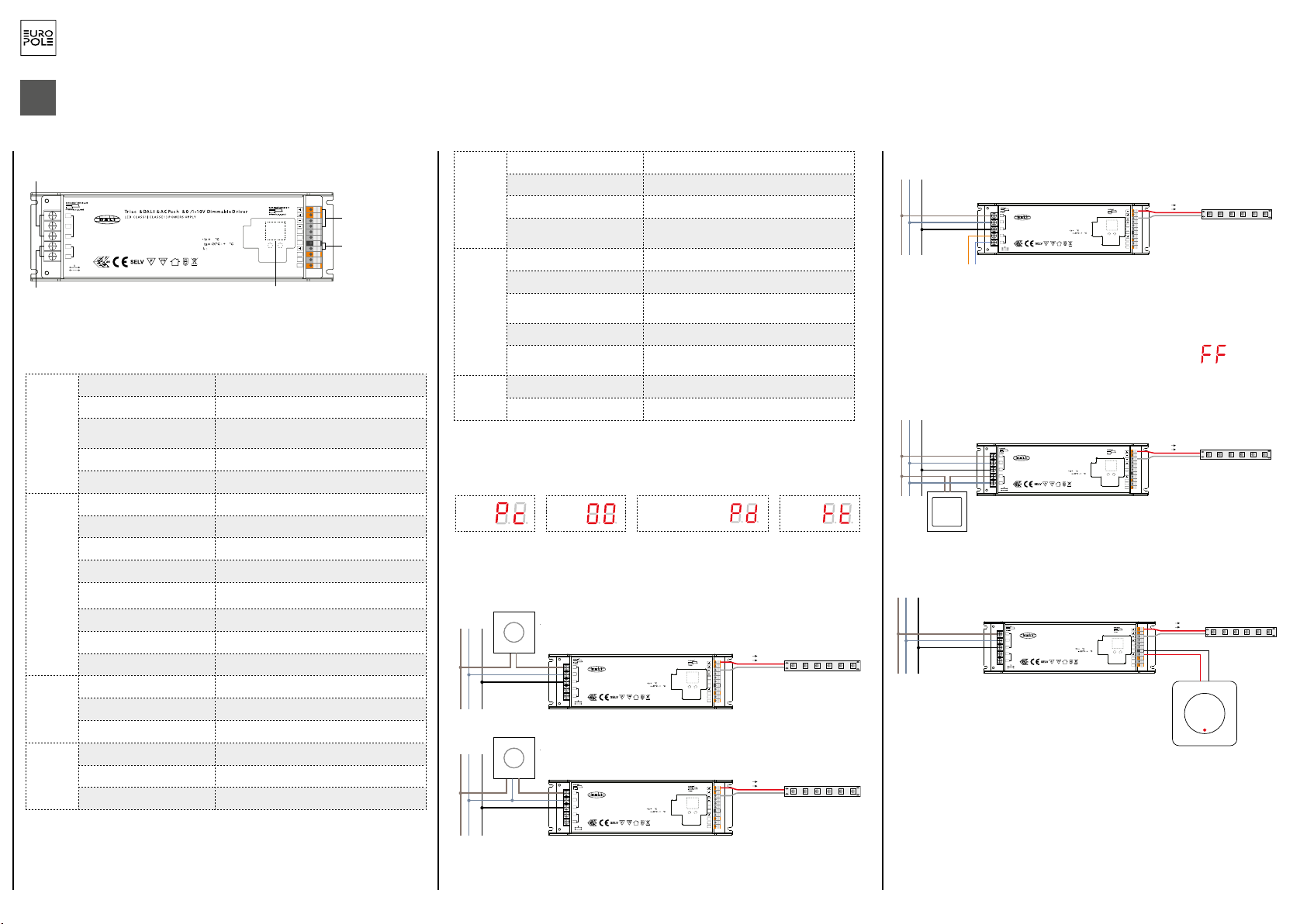
4
EUROPOLE - 19, avenue ZAC de Chassagne - 69360 TERNAY - Fax : +33 (0)4 72 24 73 42 - www.europole.net
Digita l display
AC power /
Tria c signal input
1 chane l LED outpu t
DALI/AC push intput
0-60 -9
SEC :
Outpu t Voltage=24VDC
Irated=8.3A max
Prated=200 W ma x
INPU T:
220-240V~ 1A 50/60Hz
NC=None c onnec t S uitable for D am p Location s (CONVIEN T AU X EMPLACEMENTS HUMIDES )
>0.95@230V AC
90
45
LED OUTP UT
L
N
AC INPU T
FG
DA
DA
DALI I NPUT
NC
NC
NC
PUSH DIM
L
N
DA
DA
NC
NC
0/1 -10V
GND 0/1-10V signa l input
ALIMENTATION SMART 4 in 1 - 24 VDC
ADVERTENCIA: La instalación debe realizarla una persona debidamente cualificada, y con arreglo a la normativa y reglamentación vigentes. Le recordamos que la decisión de instalar los productos en un entorno compatible y conforme a las normas de la profesión es responsabilidad exclusiva del
comprador y del instalador. Antes de instalar los dispositivos, de conectarlos a la red eléctrica o de utilizarlos, lea atentamente las instrucciones y siga sus indicaciones. Declinamos cualquier responsabilidad derivada del uso o instalación inadecuados de los productos.
La modificación de los dispositivos, aunque sea de forma parcial, anula la aplicación de la garantía.
IMPORTANTE: antes de realizar cualquier operación de instalación o mantenimiento, se debe cortar la corriente de la red eléctrica.
1. ESPECIFICACIONES TÉCNICAS
Salida
Salida de control led 1 (con 2 grupos de salida en paralelo)
Tensión constante 24V DC
Corriente máxima Máx. 4,16 A/grupo de salida (grupo1+grupo2 =
8,32 A)
Tolerancia de tensión ± 1%
Potencia máx. 200 W
Entrada
Rango de tensión 220-240V AC
Rango de frecuencia 50/60Hz
Factor de potencia >0,95@230VAC
Distorsión armónica total THD⩽15% (en carga / 230VCA)
Rendimiento 93% @ 230VCA en carga
Corriente alterna 1A @ 230VAC
Pico de corriente 65A @230VAC
Corriente de fuga < 0,5mA/230VAC
Variación
Interfaz de variación DALI/botón+Triac+0/1-10V
Rango de variación 0,1%-100%
Método de variación Modulación de ancho de pulso
Protec-
ción
Cortocircuito Sí, restablecer automáticamente tras finalizar el fallo
Sobreintensidad Sí, restablecer automáticamente tras finalizar el fallo
Sobrecalentamiento Sí, restablecer automáticamente tras finalizar el fallo
2. DIAGRAMA DE CABLEADO
TRIAC
ES
Salida de control led
Salida de señal
0/1-10V
Pantalla digital
Entrada de control
DALI/CA
Alimentación CA /
Entrada de señal
Triac
Entorno
Temperaturas de funcionamiento -25°C ~ +45°C
Temperatura máx. de la caja 90°C
Humedad de funcionamiento 10%~ 95% de humedad relativa
Temperatura y humedad de
almacenamiento -40°C ~ +80°C, 10%~ 95% humedad relativa
Seguridad y
CEM (com-
patibilidad
electroma-
gnética)
Norma de seguridad Aprobado según EN61347-1, EN61347-3-13
Tensión soportada I/P-O/P:3,75KVAC
Resistencia de aislamiento I/P-O/P:100M Ohms / 500VDC / 25°C / 70%
humedad relativa
Emisión CEM EN61347-1, EN61000-3-2,EN6111-3-3
Inmunidad CEM EN61547,EN61000-4-2,3,4,5,6,8,11, inmunidad a
la sobretensión de línea a línea de 1kV
Otros
Tiempo medio entre fallos 193,6k horas mínimo a 230VCA en carga y a 25 °C
Dimensiones 240*72*36mm(L*l*H)
1. 4 posibilidades de variación: DALI, botón pulsador, Triac, 0/1-10V
2. No utilice varias soluciones de variación simultáneamente
3. La pantalla muestra automáticamente el código correspondiente a la solución de variación
conectada al producto:
Note: DALI address can be manually assigned from 00-63-FF, by factory defaults, no DALI
address is assigned for the driver, and the display shows . Setting DALI address as
will reset the dimmer to factory defaults.
3.1 DALI address can also be assigned by DALI Master controller automatically, please refer to user manuals of
compatible DALI Masters for specific operations.
Note: The digital display will show when the DALI master is assigning addresses.
3. DALI Address Assigned by DALI Masters
4.PUSH Dimmer Mode
While connected with a AC push switch, the digital display will show “PD” which means Push Dimmer
Mode, operations under PUSH Mode are as follows:
4.1. Click the button to switch ON/OFF
4.2. Press and hold down the button to increase or decrease light intensity to desired level and release it, then
repeat the operation to adjust light intensity to opposite direction. The dimming range is from 1% to 100%.
4.3. Memory function after power off or power failure enables the device to memorize the status before power
off while power on again.
2.1 Press and hold down any of the two buttons until numeric digital display flashes, then release
the button.
2.2 Click any of the two buttons once to select a digit, click again to change the digit until the
desired DALI address appears. Click first button to set “tens” position and second button to set
“units” position. The address can be set from 00~63.
2.3 Then press and hold down any of the 2 buttons until the numeric digital display stops flashing
to confirm the setting.
0-6 0-9
2. Set DALI Address Manually While Connected with DALI Input
While connected with a Triac dimmer, different Triac dimmers from different suppliers may have different
minimum dimming levels which the driver can not be dimmed below. To dim to 1%, please make sure the
dimmer supports 1% minimum dimming level.
5. Triac Dimming Input
240.00 mm
72.00 mm 36.00 m m
Product Dimension
0-6 0-9
Wiring diagram
1.With DALI bus
2.With PUSH dimmer
3.With Triac Dimmer
4.With 0/1-10V dimmer
(AWG18-10 )
(0.55-0.86in)
(AWG20-14 )
(0.24-0.28in)
Tria c & DALI & AC Pu sh & 0/1- 10V Dim mable D river
SEC:
Output Voltage=24VDC
Irated=8.3A max
Pout=200W max
INPUT:
220-240V~ 1A 50/60Hz
LED CL ASS 1 (CL ASSE 1) P OWER SU PPLY
ta
λ>0.95@230VAC:
90
45
L
N
AC INPUT
LED OUTPUT
FG
NC
DA
DA
DALI INP UT
PUSH DI M
L
N
DA
DA
NC
NC
NC=None connect Suitable for Damp Locations (CONVIENT AUX EMPLACEMENTS HUMIDES)
NC
NC
0/1-10V
GND
0-6 0-9
L N GND
DALI bus
LED light
(AWG18-10 )
(0.55-0.86in)
(AWG20-14 )
(0.24-0.28in)
Tria c & DALI & AC Pu sh & 0/1- 10V Dim mable D river
SEC:
Output Voltage=24VDC
Irated=8.3A max
Pout=200W max
INPUT:
220-240V~ 1A 50/60Hz
LED CL ASS 1 (CL ASSE 1) P OWER SU PPLY
ta
λ>0.95@230VAC:
90
45
L
N
AC INPUT
LED OUTPUT
FG
NC
DA
DA
DALI INP UT
PUSH DI M
L
N
DA
DA
NC
NC
NC=None connect Suitable for Damp Locations (CONVIENT AUX EMPLACEMENTS HUMIDES)
NC
NC
0/1-10V
GND
0-6 0-9
L N GND
AC PUS H
(AWG18-10 )
(0.55-0.86in)
(AWG20-14 )
(0.24-0.28in)
Tria c & DALI & AC Pu sh & 0/1- 10V Dim mable D river
SEC:
Output Voltage=24VDC
Irated=8.3A max
Pout=200W max
INPUT:
220-240V~ 1A 50/60Hz
LED CL ASS 1 (CL ASSE 1) P OWER SU PPLY
ta
λ>0.95@230VAC:
90
45
L
N
AC INPUT
LED OUTPUT
FG
NC
DA
DA
DALI INP UT
PUSH DI M
L
N
DA
DA
NC
NC
NC=None connect Suitable for Damp Locations (CONVIENT AUX EMPLACEMENTS HUMIDES)
NC
NC
0/1-10V
GND
0-6 0-9
L N GND Triac dimmer (No Neutral Wire)
(AWG18-10 )
(0.55-0.86in)
(AWG20-14 )
(0.24-0.28in)
Tria c & DALI & AC Pu sh & 0/1- 10V Dim mable D river
SEC:
Output Voltage=24VDC
Irated=8.3A max
Pout=200W max
INPUT:
220-240V~ 1A 50/60Hz
LED CL ASS 1 (CL ASSE 1) P OWER SU PPLY
ta
λ>0.95@230VAC:
90
45
L
N
AC INPUT
LED OUTPUT
FG
NC
DA
DA
DALI INPUT
PUSH DI M
L
N
DA
DA
NC
NC
NC=None connect Suitable for Damp Locations (CONVIENT AUX EMPLACEMENTS HUMIDES)
NC
NC
0/1-10V
GND
0-6 0-9
L N GND
0/1-10V
Control Unit
V+ V+
V- V-
LED light
V+ V+
V- V-
LED light
V+ V+
V- V-
(AWG18-10 )
(0.55-0.86in)
(AWG20-14 )
(0.24-0.28in)
Tria c & DALI & AC Pu sh & 0/1- 10V Dim mable D river
SEC:
Output Voltage=24VDC
Irated=8.3A max
Pout=200W max
INPUT:
220-240V~ 1A 50/60Hz
LED CL ASS 1 (CL ASSE 1) P OWER SU PPLY
ta
λ>0.95@230VAC:
90
45
L
N
AC INPUT
LED OUTPUT
FG
NC
DA
DA
DALI INPUT
PUSH DI M
L
N
DA
DA
NC
NC
NC=None connect Suitable for Damp Locations (CONVIENT AUX EMPLACEMENTS HUMIDES)
NC
NC
0/1-10V
GND
0-6 0-9
L N GND Triac dimmer (With Neutral Wire)
LED light
V+ V+
V- V-
LED light
V+ V+
V- V-
Note: DALI address can be manually assigned from 00-63-FF, by factory defaults, no DALI
address is assigned for the driver, and the display shows . Setting DALI address as
will reset the dimmer to factory defaults.
3.1 DALI address can also be assigned by DALI Master controller automatically, please refer to user manuals of
compatible DALI Masters for specific operations.
Note: The digital display will show when the DALI master is assigning addresses.
3. DALI Address Assigned by DALI Masters
4.PUSH Dimmer Mode
While connected with a AC push switch, the digital display will show “PD” which means Push Dimmer
Mode, operations under PUSH Mode are as follows:
4.1. Click the button to switch ON/OFF
4.2. Press and hold down the button to increase or decrease light intensity to desired level and release it, then
repeat the operation to adjust light intensity to opposite direction. The dimming range is from 1% to 100%.
4.3. Memory function after power off or power failure enables the device to memorize the status before power
off while power on again.
2.1 Press and hold down any of the two buttons until numeric digital display flashes, then release
the button.
2.2 Click any of the two buttons once to select a digit, click again to change the digit until the
desired DALI address appears. Click first button to set “tens” position and second button to set
“units” position. The address can be set from 00~63.
2.3 Then press and hold down any of the 2 buttons until the numeric digital display stops flashing
to confirm the setting.
0-6 0-9
2. Set DALI Address Manually While Connected with DALI Input
While connected with a Triac dimmer, different Triac dimmers from different suppliers may have different
minimum dimming levels which the driver can not be dimmed below. To dim to 1%, please make sure the
dimmer supports 1% minimum dimming level.
5. Triac Dimming Input
240.0 0 mm
72.00 m m 36.00 m m
Product Dimension
0-6 0-9
Wiring diagram
1.With DALI bus
2.With PUSH dimmer
3.With Triac Dimmer
4.With 0/1-10V dimmer
(AWG18-10 )
(0.55-0.86in)
(AWG20-14 )
(0.24-0.28in)
Tria c & DALI & AC Pu sh & 0/1- 10V Dim mable D river
SEC:
Output Voltage=24VDC
Irated=8.3A max
Pout=200W max
INPUT:
220-240V~ 1A 50/60Hz
LED CL ASS 1 (CL ASSE 1) P OWER SU PPLY
ta
λ>0.95@230VAC:
90
45
L
N
AC INPUT
LED OUTPUT
FG
NC
DA
DA
DALI INP UT
PUSH DIM
L
N
DA
DA
NC
NC
NC=None connect Suitable for Damp Locations (CONVIENT AUX EMPLACEMENTS HUMIDES)
NC
NC
0/1-10V
GND
0-6 0-9
L N GND
DALI bu s
LED light
(AWG18-10 )
(0.55-0.86in)
(AWG20-14 )
(0.24-0.28in)
Tria c & DALI & AC Pu sh & 0/1- 10V Dim mable D river
SEC:
Output Voltage=24VDC
Irated=8.3A max
Pout=200W max
INPUT:
220-240V~ 1A 50/60Hz
LED CL ASS 1 (CL ASSE 1) P OWER SU PPLY
ta
λ>0.95@230VAC:
90
45
L
N
AC INPUT
LED OUTPUT
FG
NC
DA
DA
DALI INP UT
PUSH DIM
L
N
DA
DA
NC
NC
NC=None connect Suitable for Damp Locations (CONVIENT AUX EMPLACEMENTS HUMIDES)
NC
NC
0/1-10V
GND
0-6 0-9
L N GND
AC PUSH
(AWG18-10 )
(0.55-0.86in)
(AWG20-14 )
(0.24-0.28in)
Tria c & DALI & AC Pu sh & 0/1- 10V Dim mable D river
SEC:
Output Voltage=24VDC
Irated=8.3A max
Pout=200W max
INPUT:
220-240V~ 1A 50/60Hz
LED CL ASS 1 (CL ASSE 1) P OWER SU PPLY
ta
λ>0.95@230VAC:
90
45
L
N
AC INPUT
LED OUTPUT
FG
NC
DA
DA
DALI INP UT
PUSH DIM
L
N
DA
DA
NC
NC
NC=None connect Suitable for Damp Locations (CONVIENT AUX EMPLACEMENTS HUMIDES)
NC
NC
0/1-10V
GND
0-6 0-9
L N GND Triac dimmer (No Neutral Wire)
(AWG18-10 )
(0.55-0.86in)
(AWG20-14 )
(0.24-0.28in)
Tria c & DALI & AC Pu sh & 0/1- 10V Dim mable D river
SEC:
Output Voltage=24VDC
Irated=8.3A max
Pout=200W max
INPUT:
220-240V~ 1A 50/60Hz
LED CL ASS 1 (CL ASSE 1) P OWER SU PPLY
ta
λ>0.95@230VAC:
90
45
L
N
AC INPUT
LED OUTPUT
FG
NC
DA
DA
DALI INPUT
PUSH DIM
L
N
DA
DA
NC
NC
NC=None connect Suitable for Damp Locations (CONVIENT AUX EMPLACEMENTS HUMIDES)
NC
NC
0/1-10V
GND
0-6 0-9
L N GND
0/1-10V
Control Unit
V+ V+
V- V-
LED light
V+ V+
V- V-
LED light
V+ V+
V- V-
(AWG18-10 )
(0.55-0.86in)
(AWG20-14 )
(0.24-0.28in)
Tria c & DALI & AC Pu sh & 0/1- 10V Dim mable D river
SEC:
Output Voltage=24VDC
Irated=8.3A max
Pout=200W max
INPUT:
220-240V~ 1A 50/60Hz
LED CL ASS 1 (CL ASSE 1) P OWER SU PPLY
ta
λ>0.95@230VAC:
90
45
L
N
AC INPUT
LED OUTPUT
FG
NC
DA
DA
DALI INPUT
PUSH DIM
L
N
DA
DA
NC
NC
NC=None connect Suitable for Damp Locations (CONVIENT AUX EMPLACEMENTS HUMIDES)
NC
NC
0/1-10V
GND
0-6 0-9
L N GND Triac dimmer (With Neutral Wire)
LED light
V+ V+
V- V-
LED light
V+ V+
V- V-
Note: DALI address can be manually assigned from 00-63-FF, by factory defaults, no DALI
address is assigned for the driver, and the display shows . Setting DALI address as
will reset the dimmer to factory defaults.
3.1 DALI address can also be assigned by DALI Master controller automatically, please refer to user manuals of
compatible DALI Masters for specific operations.
Note: The digital display will show when the DALI master is assigning addresses.
3. DALI Address Assigned by DALI Masters
4.PUSH Dimmer Mode
While connected with a AC push switch, the digital display will show “PD” which means Push Dimmer
Mode, operations under PUSH Mode are as follows:
4.1. Click the button to switch ON/OFF
4.2. Press and hold down the button to increase or decrease light intensity to desired level and release it, then
repeat the operation to adjust light intensity to opposite direction. The dimming range is from 1% to 100%.
4.3. Memory function after power off or power failure enables the device to memorize the status before power
off while power on again.
2.1 Press and hold down any of the two buttons until numeric digital display flashes, then release
the button.
2.2 Click any of the two buttons once to select a digit, click again to change the digit until the
desired DALI address appears. Click first button to set “tens” position and second button to set
“units” position. The address can be set from 00~63.
2.3 Then press and hold down any of the 2 buttons until the numeric digital display stops flashing
to confirm the setting.
0-6 0-9
2. Set DALI Address Manually While Connected with DALI Input
While connected with a Triac dimmer, different Triac dimmers from different suppliers may have different
minimum dimming levels which the driver can not be dimmed below. To dim to 1%, please make sure the
dimmer supports 1% minimum dimming level.
5. Triac Dimming Input
240.0 0 mm
72.00 m m 36.00 m m
Product Dimension
0-6 0-9
Wiring diagram
1.With DALI bus
2.With PUSH dimmer
3.With Triac Dimmer
4.With 0/1-10V dimmer
(AWG18-10 )
(0.55-0.86in)
(AWG20-14 )
(0.24-0.28in)
Tria c & DALI & AC Pu sh & 0/1- 10V Dim mable D river
SEC:
Output Voltage=24VDC
Irated=8.3A max
Pout=200W max
INPUT:
220-240V~ 1A 50/60Hz
LED CL ASS 1 (CL ASSE 1) P OWER SU PPLY
ta
λ>0.95@230VAC:
90
45
L
N
AC INPUT
LED OUTPUT
FG
NC
DA
DA
DALI INP UT
PUSH DIM
L
N
DA
DA
NC
NC
NC=None connect Suitable for Damp Locations (CONVIENT AUX EMPLACEMENTS HUMIDES)
NC
NC
0/1-10V
GND
0-6 0-9
L N GND
DALI bu s
LED light
(AWG18-10 )
(0.55-0.86in)
(AWG20-14 )
(0.24-0.28in)
Tria c & DALI & AC Pu sh & 0/1- 10V Dim mable D river
SEC:
Output Voltage=24VDC
Irated=8.3A max
Pout=200W max
INPUT:
220-240V~ 1A 50/60Hz
LED CL ASS 1 (CL ASSE 1) P OWER SU PPLY
ta
λ>0.95@230VAC:
90
45
L
N
AC INPUT
LED OUTPUT
FG
NC
DA
DA
DALI INP UT
PUSH DIM
L
N
DA
DA
NC
NC
NC=None connect Suitable for Damp Locations (CONVIENT AUX EMPLACEMENTS HUMIDES)
NC
NC
0/1-10V
GND
0-6 0-9
L N GND
AC PUSH
(AWG18-10 )
(0.55-0.86in)
(AWG20-14 )
(0.24-0.28in)
Tria c & DALI & AC Pu sh & 0/1- 10V Dim mable D river
SEC:
Output Voltage=24VDC
Irated=8.3A max
Pout=200W max
INPUT:
220-240V~ 1A 50/60Hz
LED CL ASS 1 (CL ASSE 1) P OWER SU PPLY
ta
λ>0.95@230VAC:
90
45
L
N
AC INPUT
LED OUTPUT
FG
NC
DA
DA
DALI INP UT
PUSH DIM
L
N
DA
DA
NC
NC
NC=None connect Suitable for Damp Locations (CONVIENT AUX EMPLACEMENTS HUMIDES)
NC
NC
0/1-10V
GND
0-6 0-9
L N GND Triac dimmer (No Neutral Wire)
(AWG18-10 )
(0.55-0.86in)
(AWG20-14 )
(0.24-0.28in)
Tria c & DALI & AC Pu sh & 0/1- 10V Dim mable D river
SEC:
Output Voltage=24VDC
Irated=8.3A max
Pout=200W max
INPUT:
220-240V~ 1A 50/60Hz
LED CL ASS 1 (CL ASSE 1) P OWER SU PPLY
ta
λ>0.95@230VAC:
90
45
L
N
AC INPUT
LED OUTPUT
FG
NC
DA
DA
DALI INPUT
PUSH DIM
L
N
DA
DA
NC
NC
NC=None connect Suitable for Damp Locations (CONVIENT AUX EMPLACEMENTS HUMIDES)
NC
NC
0/1-10V
GND
0-6 0-9
L N GND
0/1-10V
Control Unit
V+ V+
V- V-
LED light
V+ V+
V- V-
LED light
V+ V+
V- V-
(AWG18-10 )
(0.55-0.86in)
(AWG20-14 )
(0.24-0.28in)
Tria c & DALI & AC Pu sh & 0/1- 10V Dim mable D river
SEC:
Output Voltage=24VDC
Irated=8.3A max
Pout=200W max
INPUT:
220-240V~ 1A 50/60Hz
LED CL ASS 1 (CL ASSE 1) P OWER SU PPLY
ta
λ>0.95@230VAC:
90
45
L
N
AC INPUT
LED OUTPUT
FG
NC
DA
DA
DALI INPUT
PUSH DIM
L
N
DA
DA
NC
NC
NC=None connect Suitable for Damp Locations (CONVIENT AUX EMPLACEMENTS HUMIDES)
NC
NC
0/1-10V
GND
0-6 0-9
L N GND Triac dimmer (With Neutral Wire)
LED light
V+ V+
V- V-
LED light
V+ V+
V- V-
Note: DALI address can be manually assigned from 00-63-FF, by factory defaults, no DALI
address is assigned for the driver, and the display shows . Setting DALI address as
will reset the dimmer to factory defaults.
3.1 DALI address can also be assigned by DALI Master controller automatically, please refer to user manuals of
compatible DALI Masters for specific operations.
Note: The digital display will show when the DALI master is assigning addresses.
3. DALI Address Assigned by DALI Masters
4.PUSH Dimmer Mode
While connected with a AC push switch, the digital display will show “PD” which means Push Dimmer
Mode, operations under PUSH Mode are as follows:
4.1. Click the button to switch ON/OFF
4.2. Press and hold down the button to increase or decrease light intensity to desired level and release it, then
repeat the operation to adjust light intensity to opposite direction. The dimming range is from 1% to 100%.
4.3. Memory function after power off or power failure enables the device to memorize the status before power
off while power on again.
2.1 Press and hold down any of the two buttons until numeric digital display flashes, then release
the button.
2.2 Click any of the two buttons once to select a digit, click again to change the digit until the
desired DALI address appears. Click first button to set “tens” position and second button to set
“units” position. The address can be set from 00~63.
2.3 Then press and hold down any of the 2 buttons until the numeric digital display stops flashing
to confirm the setting.
0-6 0-9
2. Set DALI Address Manually While Connected with DALI Input
While connected with a Triac dimmer, different Triac dimmers from different suppliers may have different
minimum dimming levels which the driver can not be dimmed below. To dim to 1%, please make sure the
dimmer supports 1% minimum dimming level.
5. Triac Dimming Input
240.0 0 mm
72.00 m m 36.00 m m
Product Dimension
0-6 0-9
Wiring diagram
1.With DALI bus
2.With PUSH dimmer
3.With Triac Dimmer
4.With 0/1-10V dimmer
(AWG18-10 )
(0.55-0.86in)
(AWG20-14 )
(0.24-0.28in)
Tria c & DALI & AC Pu sh & 0/1- 10V Dim mable D river
SEC:
Output Voltage=24VDC
Irated=8.3A max
Pout=200W max
INPUT:
220-240V~ 1A 50/60Hz
LED CL ASS 1 (CL ASSE 1) P OWER SU PPLY
ta
λ>0.95@230VAC:
90
45
L
N
AC INPUT
LED OUTPUT
FG
NC
DA
DA
DALI INP UT
PUSH DIM
L
N
DA
DA
NC
NC
NC=None connect Suitable for Damp Locations (CONVIENT AUX EMPLACEMENTS HUMIDES)
NC
NC
0/1-10V
GND
0-6 0-9
L N GND
DALI bu s
LED light
(AWG18-10 )
(0.55-0.86in)
(AWG20-14 )
(0.24-0.28in)
Tria c & DALI & AC Pu sh & 0/1- 10V Dim mable D river
SEC:
Output Voltage=24VDC
Irated=8.3A max
Pout=200W max
INPUT:
220-240V~ 1A 50/60Hz
LED CL ASS 1 (CL ASSE 1) P OWER SU PPLY
ta
λ>0.95@230VAC:
90
45
L
N
AC INPUT
LED OUTPUT
FG
NC
DA
DA
DALI INP UT
PUSH DIM
L
N
DA
DA
NC
NC
NC=None connect Suitable for Damp Locations (CONVIENT AUX EMPLACEMENTS HUMIDES)
NC
NC
0/1-10V
GND
0-6 0-9
L N GND
AC PUSH
(AWG18-10 )
(0.55-0.86in)
(AWG20-14 )
(0.24-0.28in)
Tria c & DALI & AC Pu sh & 0/1- 10V Dim mable D river
SEC:
Output Voltage=24VDC
Irated=8.3A max
Pout=200W max
INPUT:
220-240V~ 1A 50/60Hz
LED CL ASS 1 (CL ASSE 1) P OWER SU PPLY
ta
λ>0.95@230VAC:
90
45
L
N
AC INPUT
LED OUTPUT
FG
NC
DA
DA
DALI INP UT
PUSH DIM
L
N
DA
DA
NC
NC
NC=None connect Suitable for Damp Locations (CONVIENT AUX EMPLACEMENTS HUMIDES)
NC
NC
0/1-10V
GND
0-6 0-9
L N GND Triac dimmer (No Neutral Wire)
(AWG18-10 )
(0.55-0.86in)
(AWG20-14 )
(0.24-0.28in)
Tria c & DALI & AC Pu sh & 0/1- 10V Dim mable D river
SEC:
Output Voltage=24VDC
Irated=8.3A max
Pout=200W max
INPUT:
220-240V~ 1A 50/60Hz
LED CL ASS 1 (CL ASSE 1) P OWER SU PPLY
ta
λ>0.95@230VAC:
90
45
L
N
AC INPUT
LED OUTPUT
FG
NC
DA
DA
DALI INPUT
PUSH DIM
L
N
DA
DA
NC
NC
NC=None connect Suitable for Damp Locations (CONVIENT AUX EMPLACEMENTS HUMIDES)
NC
NC
0/1-10V
GND
0-6 0-9
L N GND
0/1-10V
Control Unit
V+ V+
V- V-
LED light
V+ V+
V- V-
LED light
V+ V+
V- V-
(AWG18-10 )
(0.55-0.86in)
(AWG20-14 )
(0.24-0.28in)
Tria c & DALI & AC Pu sh & 0/1- 10V Dim mable D river
SEC:
Output Voltage=24VDC
Irated=8.3A max
Pout=200W max
INPUT:
220-240V~ 1A 50/60Hz
LED CL ASS 1 (CL ASSE 1) P OWER SU PPLY
ta
λ>0.95@230VAC:
90
45
L
N
AC INPUT
LED OUTPUT
FG
NC
DA
DA
DALI INPUT
PUSH DIM
L
N
DA
DA
NC
NC
NC=None connect Suitable for Damp Locations (CONVIENT AUX EMPLACEMENTS HUMIDES)
NC
NC
0/1-10V
GND
0-6 0-9
L N GND Triac dimmer (With Neutral Wire)
LED light
V+ V+
V- V-
LED light
V+ V+
V- V-
DALI
BOTÓN PULSADOR
BOTÓN PULSADOR 0/1-10 V
Cambie la dirección DALI cuando el producto esté controlado por un bus DALI:
- Mantenga pulsado uno de los dos botones hasta que la pantalla digital parpadee
- Mantenga pulsado el botón debajo del número que desee modificar; la dirección debe estar
comprendida entre 00 y 63
- Mantenga pulsado uno de los dos botones hasta que la pantalla digital deje de parpadear
Nota: Por defecto, el controlador no tiene una dirección asignada. El valor devuelve el
controlador a los valores predeterminados de fábrica.
Regulador Triac (sin conductor neutro)
Regulador Triac (con conductor neutro)
Regulador
0/1-10 V
TRIAC DALI Botón pulsador
(Push dim) 1-10V

5
EUROPOLE - 19, avenue ZAC de Chassagne - 69360 TERNAY - Fax : +33 (0)4 72 24 73 42 - www.europole.net
Digita l display
AC power /
Tria c signal input
1 chane l LED outpu t
DALI/AC push intput
0-60 -9
SEC :
Outpu t Voltage=24VDC
Irated=8.3A max
Prated=200 W ma x
INPU T:
220-240V~ 1A 50/60Hz
NC=None c onnec t S uitable for D am p Location s (CONVIEN T AU X EMPLACEMENTS HUMIDES )
>0.95@230V AC
90
45
LED OUTP UT
L
N
AC INPU T
FG
DA
DA
DALI I NPUT
NC
NC
NC
PUSH DIM
L
N
DA
DA
NC
NC
0/1 -10V
GND 0/1-10V signa l input
ALIMENTATION SMART 4 in 1 - 24 VDC
WARNUNG: Die Installation muss von qualifizierten Fachleuten unter Einhaltung der geltenden Normen und Vorschriften durchgeführt werden. Es wird daran erinnert, dass der Käufer und Installateur die volle Verantwortung dafür tragen, dass die Produkte in einer Umgebung installiert werden, die mit
den Normen und einschlägigen Regeln kompatibel und konform ist. Lesen und befolgen Sie die Anweisungen, bevor Sie die Produkte installieren, einschalten oder verwenden. Wir übernehmen keinerlei Haftung bei einer unsachgemäßen Durchführung oder Installation der Produkte.
Die Geräte dürfen weder gänzlich noch teilweise modifiziert werden, da anderenfalls der Garantieanspruch erlischt.
WICHTIG: Schalten Sie vor allen Installations- oder Wartungsarbeiten den Netzstrom ab.
1.
TECHNISCHE SPEZIFIKATIONEN
Ausgang
LED-Steuerungsausgang 1 (mit 2 parallel geschalteten Ausgangsgruppen)
konstante Spannung 24V DC
max. Stromstärke max. 4,16 A/Ausgangsgruppe (Gruppe 1 + Gruppe
2 = 8,32 A)
Spannungstoleranz ± 1%
Leistung max. 200 W
Eingang
Spannungsbereich 220-240V AC
Frequenzbereich 50/60Hz
Leistungsfaktor >0,95@230VAC
Klirrfaktor (THD) THD⩽15% (@bei Last / 230 VAC)
Lichtausbeute 93% @ 230 VAC Last
AC-Spannung 1A @ 230VAC
Einschaltstrom 65A @230VAC
Kriechstrom < 0,5mA/230VAC
Variation
Variationsinterface DALI/Tastschalter+Triac+0/1-10V
Variationsbereich 0,1%-100%
Variationsmethode Pulsweitenmodulation
Schutz
Kurzschluss Ja, automatische Wiederherstellung nach Ende des
Fehlers
Überstrom Ja, automatische Wiederherstellung nach Ende des
Fehlers
Überhitzung Ja, automatische Wiederherstellung nach Ende des
Fehlers
2. KABELANSCHLUSSPLAN
TRIAC
DE
LED-Steuerungsaus-
gang
0/1-10V-Signalaus-
gang
Digitaldisplay
DALI/
AC-Steuerungsein-
gang
AC-Stromanschluss/
Triac-Signaleingang
Umge-
bung
Betriebstemperatur -25°C ~ +45°C
Höchsttemperatur Gehäuse 90°C
Betriebsluftfeuchtigkeit 10 % ~ 95 % relative Luftfeuchtigkeit
Lagertemperatur und Luftfeuch-
tigkeit -40°C ~ +80°C, 10%~ 95% elative Luftfeuchtigkeit
Sicherheit
und EMV
(elektro-
magne-
tische
Verträglich-
keit)
Sicherheitsstandard EN61347-1, EN61347-3-13 zugelassen
Haltespannung I/P-O/P:3,75KVAC
Isolationswiderstand I/P-O/P:100M Ohms / 500VDC / 25°C / 70%
relative Luftfeuchtigkeit
EMV-Emissionsfestigkeit EN61347-1, EN61000-3-2,EN6111-3-3
EMV-Störfestigkeit EN61547,EN61000-4-2,3,4,5,6,8,11, Übers-
pannschutz zwischen Leitungen 1 kV
Sonstiges
Mean Time Between Failures 193,6 k Stunden mindestens bei 230 VAC Last
und 25 °C
Abmessungen 240*72*36mm(L*l*H)
1. 4 Variationsmöglichkeiten: DALI, Tastschalter, Triac, 0/1-10V
2. Immer nur 1 Variationslösung gleichzeitig benutzen
3. Das Display zeigt automatisch den Code der Variationslösung an, für die das Produkt gekabelt ist:
Note: DALI address can be manually assigned from 00-63-FF, by factory defaults, no DALI
address is assigned for the driver, and the display shows . Setting DALI address as
will reset the dimmer to factory defaults.
3.1 DALI address can also be assigned by DALI Master controller automatically, please refer to user manuals of
compatible DALI Masters for specific operations.
Note: The digital display will show when the DALI master is assigning addresses.
3. DALI Address Assigned by DALI Masters
4.PUSH Dimmer Mode
While connected with a AC push switch, the digital display will show “PD” which means Push Dimmer
Mode, operations under PUSH Mode are as follows:
4.1. Click the button to switch ON/OFF
4.2. Press and hold down the button to increase or decrease light intensity to desired level and release it, then
repeat the operation to adjust light intensity to opposite direction. The dimming range is from 1% to 100%.
4.3. Memory function after power off or power failure enables the device to memorize the status before power
off while power on again.
2.1 Press and hold down any of the two buttons until numeric digital display flashes, then release
the button.
2.2 Click any of the two buttons once to select a digit, click again to change the digit until the
desired DALI address appears. Click first button to set “tens” position and second button to set
“units” position. The address can be set from 00~63.
2.3 Then press and hold down any of the 2 buttons until the numeric digital display stops flashing
to confirm the setting.
0-6 0-9
2. Set DALI Address Manually While Connected with DALI Input
While connected with a Triac dimmer, different Triac dimmers from different suppliers may have different
minimum dimming levels which the driver can not be dimmed below. To dim to 1%, please make sure the
dimmer supports 1% minimum dimming level.
5. Triac Dimming Input
240.00 mm
72.00 mm 36.00 m m
Product Dimension
0-6 0-9
Wiring diagram
1.With DALI bus
2.With PUSH dimmer
3.With Triac Dimmer
4.With 0/1-10V dimmer
(AWG18-10 )
(0.55-0.86in)
(AWG20-14 )
(0.24-0.28in)
Tria c & DALI & AC Pu sh & 0/1- 10V Dim mable D river
SEC:
Output Voltage=24VDC
Irated=8.3A max
Pout=200W max
INPUT:
220-240V~ 1A 50/60Hz
LED CL ASS 1 (CL ASSE 1) P OWER SU PPLY
ta
λ>0.95@230VAC:
90
45
L
N
AC INPUT
LED OUTPUT
FG
NC
DA
DA
DALI INP UT
PUSH DI M
L
N
DA
DA
NC
NC
NC=None connect Suitable for Damp Locations (CONVIENT AUX EMPLACEMENTS HUMIDES)
NC
NC
0/1-10V
GND
0-6 0-9
L N GND
DALI bus
LED light
(AWG18-10 )
(0.55-0.86in)
(AWG20-14 )
(0.24-0.28in)
Tria c & DALI & AC Pu sh & 0/1- 10V Dim mable D river
SEC:
Output Voltage=24VDC
Irated=8.3A max
Pout=200W max
INPUT:
220-240V~ 1A 50/60Hz
LED CL ASS 1 (CL ASSE 1) P OWER SU PPLY
ta
λ>0.95@230VAC:
90
45
L
N
AC INPUT
LED OUTPUT
FG
NC
DA
DA
DALI INP UT
PUSH DI M
L
N
DA
DA
NC
NC
NC=None connect Suitable for Damp Locations (CONVIENT AUX EMPLACEMENTS HUMIDES)
NC
NC
0/1-10V
GND
0-6 0-9
L N GND
AC PUS H
(AWG18-10 )
(0.55-0.86in)
(AWG20-14 )
(0.24-0.28in)
Tria c & DALI & AC Pu sh & 0/1- 10V Dim mable D river
SEC:
Output Voltage=24VDC
Irated=8.3A max
Pout=200W max
INPUT:
220-240V~ 1A 50/60Hz
LED CL ASS 1 (CL ASSE 1) P OWER SU PPLY
ta
λ>0.95@230VAC:
90
45
L
N
AC INPUT
LED OUTPUT
FG
NC
DA
DA
DALI INP UT
PUSH DI M
L
N
DA
DA
NC
NC
NC=None connect Suitable for Damp Locations (CONVIENT AUX EMPLACEMENTS HUMIDES)
NC
NC
0/1-10V
GND
0-6 0-9
L N GND Triac dimmer (No Neutral Wire)
(AWG18-10 )
(0.55-0.86in)
(AWG20-14 )
(0.24-0.28in)
Tria c & DALI & AC Pu sh & 0/1- 10V Dim mable D river
SEC:
Output Voltage=24VDC
Irated=8.3A max
Pout=200W max
INPUT:
220-240V~ 1A 50/60Hz
LED CL ASS 1 (CL ASSE 1) P OWER SU PPLY
ta
λ>0.95@230VAC:
90
45
L
N
AC INPUT
LED OUTPUT
FG
NC
DA
DA
DALI INPUT
PUSH DI M
L
N
DA
DA
NC
NC
NC=None connect Suitable for Damp Locations (CONVIENT AUX EMPLACEMENTS HUMIDES)
NC
NC
0/1-10V
GND
0-6 0-9
L N GND
0/1-10V
Control Unit
V+ V+
V- V-
LED light
V+ V+
V- V-
LED light
V+ V+
V- V-
(AWG18-10 )
(0.55-0.86in)
(AWG20-14 )
(0.24-0.28in)
Tria c & DALI & AC Pu sh & 0/1- 10V Dim mable D river
SEC:
Output Voltage=24VDC
Irated=8.3A max
Pout=200W max
INPUT:
220-240V~ 1A 50/60Hz
LED CL ASS 1 (CL ASSE 1) P OWER SU PPLY
ta
λ>0.95@230VAC:
90
45
L
N
AC INPUT
LED OUTPUT
FG
NC
DA
DA
DALI INPUT
PUSH DI M
L
N
DA
DA
NC
NC
NC=None connect Suitable for Damp Locations (CONVIENT AUX EMPLACEMENTS HUMIDES)
NC
NC
0/1-10V
GND
0-6 0-9
L N GND Triac dimmer (With Neutral Wire)
LED light
V+ V+
V- V-
LED light
V+ V+
V- V-
Note: DALI address can be manually assigned from 00-63-FF, by factory defaults, no DALI
address is assigned for the driver, and the display shows . Setting DALI address as
will reset the dimmer to factory defaults.
3.1 DALI address can also be assigned by DALI Master controller automatically, please refer to user manuals of
compatible DALI Masters for specific operations.
Note: The digital display will show when the DALI master is assigning addresses.
3. DALI Address Assigned by DALI Masters
4.PUSH Dimmer Mode
While connected with a AC push switch, the digital display will show “PD” which means Push Dimmer
Mode, operations under PUSH Mode are as follows:
4.1. Click the button to switch ON/OFF
4.2. Press and hold down the button to increase or decrease light intensity to desired level and release it, then
repeat the operation to adjust light intensity to opposite direction. The dimming range is from 1% to 100%.
4.3. Memory function after power off or power failure enables the device to memorize the status before power
off while power on again.
2.1 Press and hold down any of the two buttons until numeric digital display flashes, then release
the button.
2.2 Click any of the two buttons once to select a digit, click again to change the digit until the
desired DALI address appears. Click first button to set “tens” position and second button to set
“units” position. The address can be set from 00~63.
2.3 Then press and hold down any of the 2 buttons until the numeric digital display stops flashing
to confirm the setting.
0-6 0-9
2. Set DALI Address Manually While Connected with DALI Input
While connected with a Triac dimmer, different Triac dimmers from different suppliers may have different
minimum dimming levels which the driver can not be dimmed below. To dim to 1%, please make sure the
dimmer supports 1% minimum dimming level.
5. Triac Dimming Input
240.0 0 mm
72.00 m m 36.00 m m
Product Dimension
0-6 0-9
Wiring diagram
1.With DALI bus
2.With PUSH dimmer
3.With Triac Dimmer
4.With 0/1-10V dimmer
(AWG18-10 )
(0.55-0.86in)
(AWG20-14 )
(0.24-0.28in)
Tria c & DALI & AC Pu sh & 0/1- 10V Dim mable D river
SEC:
Output Voltage=24VDC
Irated=8.3A max
Pout=200W max
INPUT:
220-240V~ 1A 50/60Hz
LED CL ASS 1 (CL ASSE 1) P OWER SU PPLY
ta
λ>0.95@230VAC:
90
45
L
N
AC INPUT
LED OUTPUT
FG
NC
DA
DA
DALI INP UT
PUSH DIM
L
N
DA
DA
NC
NC
NC=None connect Suitable for Damp Locations (CONVIENT AUX EMPLACEMENTS HUMIDES)
NC
NC
0/1-10V
GND
0-6 0-9
L N GND
DALI bu s
LED light
(AWG18-10 )
(0.55-0.86in)
(AWG20-14 )
(0.24-0.28in)
Tria c & DALI & AC Pu sh & 0/1- 10V Dim mable D river
SEC:
Output Voltage=24VDC
Irated=8.3A max
Pout=200W max
INPUT:
220-240V~ 1A 50/60Hz
LED CL ASS 1 (CL ASSE 1) P OWER SU PPLY
ta
λ>0.95@230VAC:
90
45
L
N
AC INPUT
LED OUTPUT
FG
NC
DA
DA
DALI INP UT
PUSH DIM
L
N
DA
DA
NC
NC
NC=None connect Suitable for Damp Locations (CONVIENT AUX EMPLACEMENTS HUMIDES)
NC
NC
0/1-10V
GND
0-6 0-9
L N GND
AC PUSH
(AWG18-10 )
(0.55-0.86in)
(AWG20-14 )
(0.24-0.28in)
Tria c & DALI & AC Pu sh & 0/1- 10V Dim mable D river
SEC:
Output Voltage=24VDC
Irated=8.3A max
Pout=200W max
INPUT:
220-240V~ 1A 50/60Hz
LED CL ASS 1 (CL ASSE 1) P OWER SU PPLY
ta
λ>0.95@230VAC:
90
45
L
N
AC INPUT
LED OUTPUT
FG
NC
DA
DA
DALI INP UT
PUSH DIM
L
N
DA
DA
NC
NC
NC=None connect Suitable for Damp Locations (CONVIENT AUX EMPLACEMENTS HUMIDES)
NC
NC
0/1-10V
GND
0-6 0-9
L N GND Triac dimmer (No Neutral Wire)
(AWG18-10 )
(0.55-0.86in)
(AWG20-14 )
(0.24-0.28in)
Tria c & DALI & AC Pu sh & 0/1- 10V Dim mable D river
SEC:
Output Voltage=24VDC
Irated=8.3A max
Pout=200W max
INPUT:
220-240V~ 1A 50/60Hz
LED CL ASS 1 (CL ASSE 1) P OWER SU PPLY
ta
λ>0.95@230VAC:
90
45
L
N
AC INPUT
LED OUTPUT
FG
NC
DA
DA
DALI INPUT
PUSH DIM
L
N
DA
DA
NC
NC
NC=None connect Suitable for Damp Locations (CONVIENT AUX EMPLACEMENTS HUMIDES)
NC
NC
0/1-10V
GND
0-6 0-9
L N GND
0/1-10V
Control Unit
V+ V+
V- V-
LED light
V+ V+
V- V-
LED light
V+ V+
V- V-
(AWG18-10 )
(0.55-0.86in)
(AWG20-14 )
(0.24-0.28in)
Tria c & DALI & AC Pu sh & 0/1- 10V Dim mable D river
SEC:
Output Voltage=24VDC
Irated=8.3A max
Pout=200W max
INPUT:
220-240V~ 1A 50/60Hz
LED CL ASS 1 (CL ASSE 1) P OWER SU PPLY
ta
λ>0.95@230VAC:
90
45
L
N
AC INPUT
LED OUTPUT
FG
NC
DA
DA
DALI INPUT
PUSH DIM
L
N
DA
DA
NC
NC
NC=None connect Suitable for Damp Locations (CONVIENT AUX EMPLACEMENTS HUMIDES)
NC
NC
0/1-10V
GND
0-6 0-9
L N GND Triac dimmer (With Neutral Wire)
LED light
V+ V+
V- V-
LED light
V+ V+
V- V-
Note: DALI address can be manually assigned from 00-63-FF, by factory defaults, no DALI
address is assigned for the driver, and the display shows . Setting DALI address as
will reset the dimmer to factory defaults.
3.1 DALI address can also be assigned by DALI Master controller automatically, please refer to user manuals of
compatible DALI Masters for specific operations.
Note: The digital display will show when the DALI master is assigning addresses.
3. DALI Address Assigned by DALI Masters
4.PUSH Dimmer Mode
While connected with a AC push switch, the digital display will show “PD” which means Push Dimmer
Mode, operations under PUSH Mode are as follows:
4.1. Click the button to switch ON/OFF
4.2. Press and hold down the button to increase or decrease light intensity to desired level and release it, then
repeat the operation to adjust light intensity to opposite direction. The dimming range is from 1% to 100%.
4.3. Memory function after power off or power failure enables the device to memorize the status before power
off while power on again.
2.1 Press and hold down any of the two buttons until numeric digital display flashes, then release
the button.
2.2 Click any of the two buttons once to select a digit, click again to change the digit until the
desired DALI address appears. Click first button to set “tens” position and second button to set
“units” position. The address can be set from 00~63.
2.3 Then press and hold down any of the 2 buttons until the numeric digital display stops flashing
to confirm the setting.
0-6 0-9
2. Set DALI Address Manually While Connected with DALI Input
While connected with a Triac dimmer, different Triac dimmers from different suppliers may have different
minimum dimming levels which the driver can not be dimmed below. To dim to 1%, please make sure the
dimmer supports 1% minimum dimming level.
5. Triac Dimming Input
240.0 0 mm
72.00 m m 36.00 m m
Product Dimension
0-6 0-9
Wiring diagram
1.With DALI bus
2.With PUSH dimmer
3.With Triac Dimmer
4.With 0/1-10V dimmer
(AWG18-10 )
(0.55-0.86in)
(AWG20-14 )
(0.24-0.28in)
Tria c & DALI & AC Pu sh & 0/1- 10V Dim mable D river
SEC:
Output Voltage=24VDC
Irated=8.3A max
Pout=200W max
INPUT:
220-240V~ 1A 50/60Hz
LED CL ASS 1 (CL ASSE 1) P OWER SU PPLY
ta
λ>0.95@230VAC:
90
45
L
N
AC INPUT
LED OUTPUT
FG
NC
DA
DA
DALI INP UT
PUSH DIM
L
N
DA
DA
NC
NC
NC=None connect Suitable for Damp Locations (CONVIENT AUX EMPLACEMENTS HUMIDES)
NC
NC
0/1-10V
GND
0-6 0-9
L N GND
DALI bu s
LED light
(AWG18-10 )
(0.55-0.86in)
(AWG20-14 )
(0.24-0.28in)
Tria c & DALI & AC Pu sh & 0/1- 10V Dim mable D river
SEC:
Output Voltage=24VDC
Irated=8.3A max
Pout=200W max
INPUT:
220-240V~ 1A 50/60Hz
LED CL ASS 1 (CL ASSE 1) P OWER SU PPLY
ta
λ>0.95@230VAC:
90
45
L
N
AC INPUT
LED OUTPUT
FG
NC
DA
DA
DALI INP UT
PUSH DIM
L
N
DA
DA
NC
NC
NC=None connect Suitable for Damp Locations (CONVIENT AUX EMPLACEMENTS HUMIDES)
NC
NC
0/1-10V
GND
0-6 0-9
L N GND
AC PUSH
(AWG18-10 )
(0.55-0.86in)
(AWG20-14 )
(0.24-0.28in)
Tria c & DALI & AC Pu sh & 0/1- 10V Dim mable D river
SEC:
Output Voltage=24VDC
Irated=8.3A max
Pout=200W max
INPUT:
220-240V~ 1A 50/60Hz
LED CL ASS 1 (CL ASSE 1) P OWER SU PPLY
ta
λ>0.95@230VAC:
90
45
L
N
AC INPUT
LED OUTPUT
FG
NC
DA
DA
DALI INP UT
PUSH DIM
L
N
DA
DA
NC
NC
NC=None connect Suitable for Damp Locations (CONVIENT AUX EMPLACEMENTS HUMIDES)
NC
NC
0/1-10V
GND
0-6 0-9
L N GND Triac dimmer (No Neutral Wire)
(AWG18-10 )
(0.55-0.86in)
(AWG20-14 )
(0.24-0.28in)
Tria c & DALI & AC Pu sh & 0/1- 10V Dim mable D river
SEC:
Output Voltage=24VDC
Irated=8.3A max
Pout=200W max
INPUT:
220-240V~ 1A 50/60Hz
LED CL ASS 1 (CL ASSE 1) P OWER SU PPLY
ta
λ>0.95@230VAC:
90
45
L
N
AC INPUT
LED OUTPUT
FG
NC
DA
DA
DALI INPUT
PUSH DIM
L
N
DA
DA
NC
NC
NC=None connect Suitable for Damp Locations (CONVIENT AUX EMPLACEMENTS HUMIDES)
NC
NC
0/1-10V
GND
0-6 0-9
L N GND
0/1-10V
Control Unit
V+ V+
V- V-
LED light
V+ V+
V- V-
LED light
V+ V+
V- V-
(AWG18-10 )
(0.55-0.86in)
(AWG20-14 )
(0.24-0.28in)
Tria c & DALI & AC Pu sh & 0/1- 10V Dim mable D river
SEC:
Output Voltage=24VDC
Irated=8.3A max
Pout=200W max
INPUT:
220-240V~ 1A 50/60Hz
LED CL ASS 1 (CL ASSE 1) P OWER SU PPLY
ta
λ>0.95@230VAC:
90
45
L
N
AC INPUT
LED OUTPUT
FG
NC
DA
DA
DALI INPUT
PUSH DIM
L
N
DA
DA
NC
NC
NC=None connect Suitable for Damp Locations (CONVIENT AUX EMPLACEMENTS HUMIDES)
NC
NC
0/1-10V
GND
0-6 0-9
L N GND Triac dimmer (With Neutral Wire)
LED light
V+ V+
V- V-
LED light
V+ V+
V- V-
Note: DALI address can be manually assigned from 00-63-FF, by factory defaults, no DALI
address is assigned for the driver, and the display shows . Setting DALI address as
will reset the dimmer to factory defaults.
3.1 DALI address can also be assigned by DALI Master controller automatically, please refer to user manuals of
compatible DALI Masters for specific operations.
Note: The digital display will show when the DALI master is assigning addresses.
3. DALI Address Assigned by DALI Masters
4.PUSH Dimmer Mode
While connected with a AC push switch, the digital display will show “PD” which means Push Dimmer
Mode, operations under PUSH Mode are as follows:
4.1. Click the button to switch ON/OFF
4.2. Press and hold down the button to increase or decrease light intensity to desired level and release it, then
repeat the operation to adjust light intensity to opposite direction. The dimming range is from 1% to 100%.
4.3. Memory function after power off or power failure enables the device to memorize the status before power
off while power on again.
2.1 Press and hold down any of the two buttons until numeric digital display flashes, then release
the button.
2.2 Click any of the two buttons once to select a digit, click again to change the digit until the
desired DALI address appears. Click first button to set “tens” position and second button to set
“units” position. The address can be set from 00~63.
2.3 Then press and hold down any of the 2 buttons until the numeric digital display stops flashing
to confirm the setting.
0-6 0-9
2. Set DALI Address Manually While Connected with DALI Input
While connected with a Triac dimmer, different Triac dimmers from different suppliers may have different
minimum dimming levels which the driver can not be dimmed below. To dim to 1%, please make sure the
dimmer supports 1% minimum dimming level.
5. Triac Dimming Input
240.0 0 mm
72.00 m m 36.00 m m
Product Dimension
0-6 0-9
Wiring diagram
1.With DALI bus
2.With PUSH dimmer
3.With Triac Dimmer
4.With 0/1-10V dimmer
(AWG18-10 )
(0.55-0.86in)
(AWG20-14 )
(0.24-0.28in)
Tria c & DALI & AC Pu sh & 0/1- 10V Dim mable D river
SEC:
Output Voltage=24VDC
Irated=8.3A max
Pout=200W max
INPUT:
220-240V~ 1A 50/60Hz
LED CL ASS 1 (CL ASSE 1) P OWER SU PPLY
ta
λ>0.95@230VAC:
90
45
L
N
AC INPUT
LED OUTPUT
FG
NC
DA
DA
DALI INP UT
PUSH DIM
L
N
DA
DA
NC
NC
NC=None connect Suitable for Damp Locations (CONVIENT AUX EMPLACEMENTS HUMIDES)
NC
NC
0/1-10V
GND
0-6 0-9
L N GND
DALI bu s
LED light
(AWG18-10 )
(0.55-0.86in)
(AWG20-14 )
(0.24-0.28in)
Tria c & DALI & AC Pu sh & 0/1- 10V Dim mable D river
SEC:
Output Voltage=24VDC
Irated=8.3A max
Pout=200W max
INPUT:
220-240V~ 1A 50/60Hz
LED CL ASS 1 (CL ASSE 1) P OWER SU PPLY
ta
λ>0.95@230VAC:
90
45
L
N
AC INPUT
LED OUTPUT
FG
NC
DA
DA
DALI INP UT
PUSH DIM
L
N
DA
DA
NC
NC
NC=None connect Suitable for Damp Locations (CONVIENT AUX EMPLACEMENTS HUMIDES)
NC
NC
0/1-10V
GND
0-6 0-9
L N GND
AC PUSH
(AWG18-10 )
(0.55-0.86in)
(AWG20-14 )
(0.24-0.28in)
Tria c & DALI & AC Pu sh & 0/1- 10V Dim mable D river
SEC:
Output Voltage=24VDC
Irated=8.3A max
Pout=200W max
INPUT:
220-240V~ 1A 50/60Hz
LED CL ASS 1 (CL ASSE 1) P OWER SU PPLY
ta
λ>0.95@230VAC:
90
45
L
N
AC INPUT
LED OUTPUT
FG
NC
DA
DA
DALI INP UT
PUSH DIM
L
N
DA
DA
NC
NC
NC=None connect Suitable for Damp Locations (CONVIENT AUX EMPLACEMENTS HUMIDES)
NC
NC
0/1-10V
GND
0-6 0-9
L N GND Triac dimmer (No Neutral Wire)
(AWG18-10 )
(0.55-0.86in)
(AWG20-14 )
(0.24-0.28in)
Tria c & DALI & AC Pu sh & 0/1- 10V Dim mable D river
SEC:
Output Voltage=24VDC
Irated=8.3A max
Pout=200W max
INPUT:
220-240V~ 1A 50/60Hz
LED CL ASS 1 (CL ASSE 1) P OWER SU PPLY
ta
λ>0.95@230VAC:
90
45
L
N
AC INPUT
LED OUTPUT
FG
NC
DA
DA
DALI INPUT
PUSH DIM
L
N
DA
DA
NC
NC
NC=None connect Suitable for Damp Locations (CONVIENT AUX EMPLACEMENTS HUMIDES)
NC
NC
0/1-10V
GND
0-6 0-9
L N GND
0/1-10V
Control Unit
V+ V+
V- V-
LED light
V+ V+
V- V-
LED light
V+ V+
V- V-
(AWG18-10 )
(0.55-0.86in)
(AWG20-14 )
(0.24-0.28in)
Tria c & DALI & AC Pu sh & 0/1- 10V Dim mable D river
SEC:
Output Voltage=24VDC
Irated=8.3A max
Pout=200W max
INPUT:
220-240V~ 1A 50/60Hz
LED CL ASS 1 (CL ASSE 1) P OWER SU PPLY
ta
λ>0.95@230VAC:
90
45
L
N
AC INPUT
LED OUTPUT
FG
NC
DA
DA
DALI INPUT
PUSH DIM
L
N
DA
DA
NC
NC
NC=None connect Suitable for Damp Locations (CONVIENT AUX EMPLACEMENTS HUMIDES)
NC
NC
0/1-10V
GND
0-6 0-9
L N GND Triac dimmer (With Neutral Wire)
LED light
V+ V+
V- V-
LED light
V+ V+
V- V-
DALI
TASTSCHALTER
TASTSCHALTER 0/1-10V
DALI-Adresse ändern, wenn das Produkt über DALI-Bus gesteuert wird:
- Einen der zwei Tastschalter drücken, bis das Digitaldisplay blinkt
- Den Tastschalter unter der zu ändernden Ziffer drücken, die Adresse muss zwischen 00 und 63
liegen
- Einen der zwei Tastschalter drücken, bis das Digitaldisplay nicht mehr blinkt
Hinweis: Dem Steuergerät ist werkseitig keine Adresse zugeteilt. Bei Zuteilung von wird
das Steuergerät auf die Standardeinstellungen zurückgesetzt.
Triac-Dimmer (ohne Nullleiter)
Triac-Dimmer (mit Nullleiter)
Dimmer
0/1-10V
TRIAC DALI Tastschalter
(Push dim) 1-10V
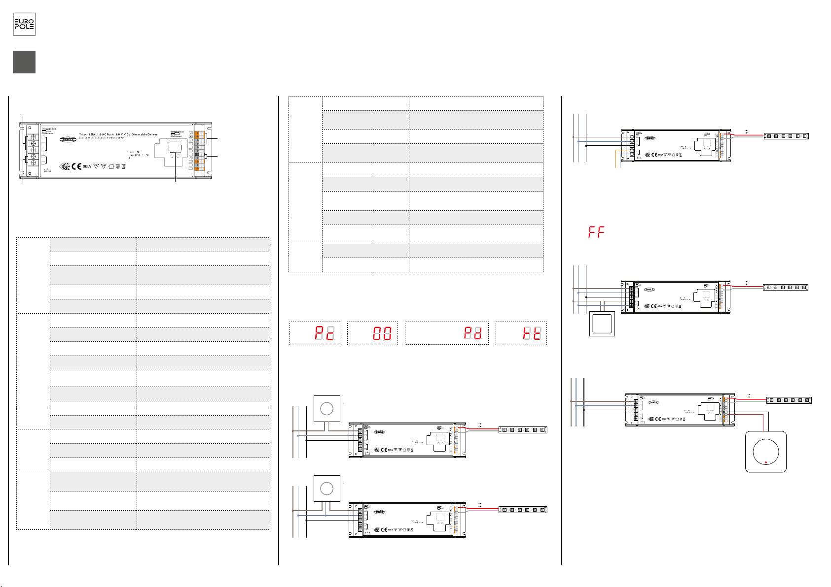
6
EUROPOLE - 19, avenue ZAC de Chassagne - 69360 TERNAY - Fax : +33 (0)4 72 24 73 42 - www.europole.net
Digita l display
AC power /
Tria c signal input
1 chane l LED outpu t
DALI/AC push intput
0-60 -9
SEC :
Outpu t Voltage=24VDC
Irated=8.3A max
Prated=200 W ma x
INPU T:
220-240V~ 1A 50/60Hz
NC=None c onnec t S uitable for D am p Location s (CONVIEN T AU X EMPLACEMENTS HUMIDES )
>0.95@230V AC
90
45
LED OUTP UT
L
N
AC INPU T
FG
DA
DA
DALI I NPUT
NC
NC
NC
PUSH DIM
L
N
DA
DA
NC
NC
0/1 -10V
GND 0/1-10V signa l input
ALIMENTATION SMART 4 in 1 - 24 VDC
ATTENZIONE: L’installazione deve essere effettuata da tecnici qualificati e nel rispetto delle norme e regolamentazioni in vigore. Si ricorda che l’acquirente e l’installatore sono le uniche persone responsabili della decisione di installare i prodotti all’interno di un ambiente che sia idoneo e conforme alle
norme e alle procedure necessarie. Si prega di leggere e seguire le istruzioni prima di procedere all’installazione e di mettere in tensione o utilizzare i prodotti. Eventuali danni causati da montaggio e installazione inadeguati dei prodotti non rientrano nelle nostre responsabilità.
La garanzia si applica soltanto se i prodotti non vengono manomessi, anche solo parzialmente.
IMPORTANTE: Prima di procedere a qualunque operazione di installazione o di manutenzione, staccare sempre la corrente dell’impianto.
1.
SPECIFICHE TECNICHE
Uscita
Uscita di controllo LED 1 (con 2 gruppi di uscita paralleli)
Tensione costante 24V DC
Corrente massima Massimo 4,16 A/gruppo di uscita (gruppo1 +
gruppo2 = 8,32 A)
Tolleranza della tensione ± 1%
Potenza max 200W
Ingresso
Intervallo della tensione 220-240V AC
Intervallo della frequenza 50/60Hz
Fattore della potenza >0,95@230VAC
Distorsione armonica totale THD⩽15% (@A carico / 230 V CA)
Rendimento 93% @ 230 V CA a carico
Corrente alternata 1A @ 230VAC
Picco di corrente 65A @230VAC
Corrente di dispersione < 0,5mA/230VAC
Dimming
Interfaccia di dimming DALI/Pulsante+Triac+0/1-10 V
Intervallo di dimming 0,1%-100%
Metodo di dimming Modulazione della larghezza dell’impulso
Prote-
zione
Corto circuito Sì, recupero automatico dopo la correzione del
difetto
Sovracorrente Sì, recupero automatico dopo la correzione del
difetto
Surriscaldamento Sì, recupero automatico dopo la correzione del
difetto
2. SCHEMA DI CABLAGGIO
TRIAC
IT
Uscita di controllo LED
Uscita del segnale 0
/ 1-10 V
Schermo
digitale
Immissione
controllo DALI/AC
Alimentazione CA
/ Ingresso segnale
Triac
Ambiente
Temperature di funzionamento -25°C ~ +45°C
Temperatura massima dell’in-
volucro 90°C
Umidità di funzionamento 10-95% di umidità relativa
Temperatura e umidità di conser-
vazione -40°C ~ +80°C, 10%~ 95% umidità relativa
Sicurezza
ed EMC
(compatibi-
lità elettro-
magnetica)
Standard di sicurezza Approvazione EN61347-1,EN61347-3-13
Tensione di tenuta I/P-O/P:3,75KVAC
Resistenza dell’isolamento I/P-O/P:100M Ohms / 500VDC / 25°C / 70%
umidità relativa
Emissioni EMC EN61347-1, EN61000-3-2,EN6111-3-3
Immunità EMC EN61547,EN61000-4-2,3,4,5,6,8,11, Immunità alla
sovratensione linea-linea 1 kV
Altro
Tempo medio tra guasti Minimo 193,6k ore a 230 V CA a carico e a 25 °C
Dimensioni 240*72*36mm(L*l*H)
1. 4 opzioni per il dimming: DALI , pulsante, Triac, 0/1-10 V
2. Utilizzare una sola soluzione di dimming alla volta
3. Lo schermo visualizzerà automaticamente un codice corrispondente alla soluzione di dimmi-
ng cablata del prodotto:
Note: DALI address can be manually assigned from 00-63-FF, by factory defaults, no DALI
address is assigned for the driver, and the display shows . Setting DALI address as
will reset the dimmer to factory defaults.
3.1 DALI address can also be assigned by DALI Master controller automatically, please refer to user manuals of
compatible DALI Masters for specific operations.
Note: The digital display will show when the DALI master is assigning addresses.
3. DALI Address Assigned by DALI Masters
4.PUSH Dimmer Mode
While connected with a AC push switch, the digital display will show “PD” which means Push Dimmer
Mode, operations under PUSH Mode are as follows:
4.1. Click the button to switch ON/OFF
4.2. Press and hold down the button to increase or decrease light intensity to desired level and release it, then
repeat the operation to adjust light intensity to opposite direction. The dimming range is from 1% to 100%.
4.3. Memory function after power off or power failure enables the device to memorize the status before power
off while power on again.
2.1 Press and hold down any of the two buttons until numeric digital display flashes, then release
the button.
2.2 Click any of the two buttons once to select a digit, click again to change the digit until the
desired DALI address appears. Click first button to set “tens” position and second button to set
“units” position. The address can be set from 00~63.
2.3 Then press and hold down any of the 2 buttons until the numeric digital display stops flashing
to confirm the setting.
0-6 0-9
2. Set DALI Address Manually While Connected with DALI Input
While connected with a Triac dimmer, different Triac dimmers from different suppliers may have different
minimum dimming levels which the driver can not be dimmed below. To dim to 1%, please make sure the
dimmer supports 1% minimum dimming level.
5. Triac Dimming Input
240.00 mm
72.00 mm 36.00 m m
Product Dimension
0-6 0-9
Wiring diagram
1.With DALI bus
2.With PUSH dimmer
3.With Triac Dimmer
4.With 0/1-10V dimmer
(AWG18-10 )
(0.55-0.86in)
(AWG20-14 )
(0.24-0.28in)
Tria c & DALI & AC Pu sh & 0/1- 10V Dim mable D river
SEC:
Output Voltage=24VDC
Irated=8.3A max
Pout=200W max
INPUT:
220-240V~ 1A 50/60Hz
LED CL ASS 1 (CL ASSE 1) P OWER SU PPLY
ta
λ>0.95@230VAC:
90
45
L
N
AC INPUT
LED OUTPUT
FG
NC
DA
DA
DALI INP UT
PUSH DI M
L
N
DA
DA
NC
NC
NC=None connect Suitable for Damp Locations (CONVIENT AUX EMPLACEMENTS HUMIDES)
NC
NC
0/1-10V
GND
0-6 0-9
L N GND
DALI bus
LED light
(AWG18-10 )
(0.55-0.86in)
(AWG20-14 )
(0.24-0.28in)
Tria c & DALI & AC Pu sh & 0/1- 10V Dim mable D river
SEC:
Output Voltage=24VDC
Irated=8.3A max
Pout=200W max
INPUT:
220-240V~ 1A 50/60Hz
LED CL ASS 1 (CL ASSE 1) P OWER SU PPLY
ta
λ>0.95@230VAC:
90
45
L
N
AC INPUT
LED OUTPUT
FG
NC
DA
DA
DALI INP UT
PUSH DI M
L
N
DA
DA
NC
NC
NC=None connect Suitable for Damp Locations (CONVIENT AUX EMPLACEMENTS HUMIDES)
NC
NC
0/1-10V
GND
0-6 0-9
L N GND
AC PUS H
(AWG18-10 )
(0.55-0.86in)
(AWG20-14 )
(0.24-0.28in)
Tria c & DALI & AC Pu sh & 0/1- 10V Dim mable D river
SEC:
Output Voltage=24VDC
Irated=8.3A max
Pout=200W max
INPUT:
220-240V~ 1A 50/60Hz
LED CL ASS 1 (CL ASSE 1) P OWER SU PPLY
ta
λ>0.95@230VAC:
90
45
L
N
AC INPUT
LED OUTPUT
FG
NC
DA
DA
DALI INP UT
PUSH DI M
L
N
DA
DA
NC
NC
NC=None connect Suitable for Damp Locations (CONVIENT AUX EMPLACEMENTS HUMIDES)
NC
NC
0/1-10V
GND
0-6 0-9
L N GND Triac dimmer (No Neutral Wire)
(AWG18-10 )
(0.55-0.86in)
(AWG20-14 )
(0.24-0.28in)
Tria c & DALI & AC Pu sh & 0/1- 10V Dim mable D river
SEC:
Output Voltage=24VDC
Irated=8.3A max
Pout=200W max
INPUT:
220-240V~ 1A 50/60Hz
LED CL ASS 1 (CL ASSE 1) P OWER SU PPLY
ta
λ>0.95@230VAC:
90
45
L
N
AC INPUT
LED OUTPUT
FG
NC
DA
DA
DALI INPUT
PUSH DI M
L
N
DA
DA
NC
NC
NC=None connect Suitable for Damp Locations (CONVIENT AUX EMPLACEMENTS HUMIDES)
NC
NC
0/1-10V
GND
0-6 0-9
L N GND
0/1-10V
Control Unit
V+ V+
V- V-
LED light
V+ V+
V- V-
LED light
V+ V+
V- V-
(AWG18-10 )
(0.55-0.86in)
(AWG20-14 )
(0.24-0.28in)
Tria c & DALI & AC Pu sh & 0/1- 10V Dim mable D river
SEC:
Output Voltage=24VDC
Irated=8.3A max
Pout=200W max
INPUT:
220-240V~ 1A 50/60Hz
LED CL ASS 1 (CL ASSE 1) P OWER SU PPLY
ta
λ>0.95@230VAC:
90
45
L
N
AC INPUT
LED OUTPUT
FG
NC
DA
DA
DALI INPUT
PUSH DI M
L
N
DA
DA
NC
NC
NC=None connect Suitable for Damp Locations (CONVIENT AUX EMPLACEMENTS HUMIDES)
NC
NC
0/1-10V
GND
0-6 0-9
L N GND Triac dimmer (With Neutral Wire)
LED light
V+ V+
V- V-
LED light
V+ V+
V- V-
Note: DALI address can be manually assigned from 00-63-FF, by factory defaults, no DALI
address is assigned for the driver, and the display shows . Setting DALI address as
will reset the dimmer to factory defaults.
3.1 DALI address can also be assigned by DALI Master controller automatically, please refer to user manuals of
compatible DALI Masters for specific operations.
Note: The digital display will show when the DALI master is assigning addresses.
3. DALI Address Assigned by DALI Masters
4.PUSH Dimmer Mode
While connected with a AC push switch, the digital display will show “PD” which means Push Dimmer
Mode, operations under PUSH Mode are as follows:
4.1. Click the button to switch ON/OFF
4.2. Press and hold down the button to increase or decrease light intensity to desired level and release it, then
repeat the operation to adjust light intensity to opposite direction. The dimming range is from 1% to 100%.
4.3. Memory function after power off or power failure enables the device to memorize the status before power
off while power on again.
2.1 Press and hold down any of the two buttons until numeric digital display flashes, then release
the button.
2.2 Click any of the two buttons once to select a digit, click again to change the digit until the
desired DALI address appears. Click first button to set “tens” position and second button to set
“units” position. The address can be set from 00~63.
2.3 Then press and hold down any of the 2 buttons until the numeric digital display stops flashing
to confirm the setting.
0-6 0-9
2. Set DALI Address Manually While Connected with DALI Input
While connected with a Triac dimmer, different Triac dimmers from different suppliers may have different
minimum dimming levels which the driver can not be dimmed below. To dim to 1%, please make sure the
dimmer supports 1% minimum dimming level.
5. Triac Dimming Input
240.0 0 mm
72.00 m m 36.00 m m
Product Dimension
0-6 0-9
Wiring diagram
1.With DALI bus
2.With PUSH dimmer
3.With Triac Dimmer
4.With 0/1-10V dimmer
(AWG18-10 )
(0.55-0.86in)
(AWG20-14 )
(0.24-0.28in)
Tria c & DALI & AC Pu sh & 0/1- 10V Dim mable D river
SEC:
Output Voltage=24VDC
Irated=8.3A max
Pout=200W max
INPUT:
220-240V~ 1A 50/60Hz
LED CL ASS 1 (CL ASSE 1) P OWER SU PPLY
ta
λ>0.95@230VAC:
90
45
L
N
AC INPUT
LED OUTPUT
FG
NC
DA
DA
DALI INP UT
PUSH DIM
L
N
DA
DA
NC
NC
NC=None connect Suitable for Damp Locations (CONVIENT AUX EMPLACEMENTS HUMIDES)
NC
NC
0/1-10V
GND
0-6 0-9
L N GND
DALI bu s
LED light
(AWG18-10 )
(0.55-0.86in)
(AWG20-14 )
(0.24-0.28in)
Tria c & DALI & AC Pu sh & 0/1- 10V Dim mable D river
SEC:
Output Voltage=24VDC
Irated=8.3A max
Pout=200W max
INPUT:
220-240V~ 1A 50/60Hz
LED CL ASS 1 (CL ASSE 1) P OWER SU PPLY
ta
λ>0.95@230VAC:
90
45
L
N
AC INPUT
LED OUTPUT
FG
NC
DA
DA
DALI INP UT
PUSH DIM
L
N
DA
DA
NC
NC
NC=None connect Suitable for Damp Locations (CONVIENT AUX EMPLACEMENTS HUMIDES)
NC
NC
0/1-10V
GND
0-6 0-9
L N GND
AC PUSH
(AWG18-10 )
(0.55-0.86in)
(AWG20-14 )
(0.24-0.28in)
Tria c & DALI & AC Pu sh & 0/1- 10V Dim mable D river
SEC:
Output Voltage=24VDC
Irated=8.3A max
Pout=200W max
INPUT:
220-240V~ 1A 50/60Hz
LED CL ASS 1 (CL ASSE 1) P OWER SU PPLY
ta
λ>0.95@230VAC:
90
45
L
N
AC INPUT
LED OUTPUT
FG
NC
DA
DA
DALI INP UT
PUSH DIM
L
N
DA
DA
NC
NC
NC=None connect Suitable for Damp Locations (CONVIENT AUX EMPLACEMENTS HUMIDES)
NC
NC
0/1-10V
GND
0-6 0-9
L N GND Triac dimmer (No Neutral Wire)
(AWG18-10 )
(0.55-0.86in)
(AWG20-14 )
(0.24-0.28in)
Tria c & DALI & AC Pu sh & 0/1- 10V Dim mable D river
SEC:
Output Voltage=24VDC
Irated=8.3A max
Pout=200W max
INPUT:
220-240V~ 1A 50/60Hz
LED CL ASS 1 (CL ASSE 1) P OWER SU PPLY
ta
λ>0.95@230VAC:
90
45
L
N
AC INPUT
LED OUTPUT
FG
NC
DA
DA
DALI INPUT
PUSH DIM
L
N
DA
DA
NC
NC
NC=None connect Suitable for Damp Locations (CONVIENT AUX EMPLACEMENTS HUMIDES)
NC
NC
0/1-10V
GND
0-6 0-9
L N GND
0/1-10V
Control Unit
V+ V+
V- V-
LED light
V+ V+
V- V-
LED light
V+ V+
V- V-
(AWG18-10 )
(0.55-0.86in)
(AWG20-14 )
(0.24-0.28in)
Tria c & DALI & AC Pu sh & 0/1- 10V Dim mable D river
SEC:
Output Voltage=24VDC
Irated=8.3A max
Pout=200W max
INPUT:
220-240V~ 1A 50/60Hz
LED CL ASS 1 (CL ASSE 1) P OWER SU PPLY
ta
λ>0.95@230VAC:
90
45
L
N
AC INPUT
LED OUTPUT
FG
NC
DA
DA
DALI INPUT
PUSH DIM
L
N
DA
DA
NC
NC
NC=None connect Suitable for Damp Locations (CONVIENT AUX EMPLACEMENTS HUMIDES)
NC
NC
0/1-10V
GND
0-6 0-9
L N GND Triac dimmer (With Neutral Wire)
LED light
V+ V+
V- V-
LED light
V+ V+
V- V-
Note: DALI address can be manually assigned from 00-63-FF, by factory defaults, no DALI
address is assigned for the driver, and the display shows . Setting DALI address as
will reset the dimmer to factory defaults.
3.1 DALI address can also be assigned by DALI Master controller automatically, please refer to user manuals of
compatible DALI Masters for specific operations.
Note: The digital display will show when the DALI master is assigning addresses.
3. DALI Address Assigned by DALI Masters
4.PUSH Dimmer Mode
While connected with a AC push switch, the digital display will show “PD” which means Push Dimmer
Mode, operations under PUSH Mode are as follows:
4.1. Click the button to switch ON/OFF
4.2. Press and hold down the button to increase or decrease light intensity to desired level and release it, then
repeat the operation to adjust light intensity to opposite direction. The dimming range is from 1% to 100%.
4.3. Memory function after power off or power failure enables the device to memorize the status before power
off while power on again.
2.1 Press and hold down any of the two buttons until numeric digital display flashes, then release
the button.
2.2 Click any of the two buttons once to select a digit, click again to change the digit until the
desired DALI address appears. Click first button to set “tens” position and second button to set
“units” position. The address can be set from 00~63.
2.3 Then press and hold down any of the 2 buttons until the numeric digital display stops flashing
to confirm the setting.
0-6 0-9
2. Set DALI Address Manually While Connected with DALI Input
While connected with a Triac dimmer, different Triac dimmers from different suppliers may have different
minimum dimming levels which the driver can not be dimmed below. To dim to 1%, please make sure the
dimmer supports 1% minimum dimming level.
5. Triac Dimming Input
240.0 0 mm
72.00 m m 36.00 m m
Product Dimension
0-6 0-9
Wiring diagram
1.With DALI bus
2.With PUSH dimmer
3.With Triac Dimmer
4.With 0/1-10V dimmer
(AWG18-10 )
(0.55-0.86in)
(AWG20-14 )
(0.24-0.28in)
Tria c & DALI & AC Pu sh & 0/1- 10V Dim mable D river
SEC:
Output Voltage=24VDC
Irated=8.3A max
Pout=200W max
INPUT:
220-240V~ 1A 50/60Hz
LED CL ASS 1 (CL ASSE 1) P OWER SU PPLY
ta
λ>0.95@230VAC:
90
45
L
N
AC INPUT
LED OUTPUT
FG
NC
DA
DA
DALI INP UT
PUSH DIM
L
N
DA
DA
NC
NC
NC=None connect Suitable for Damp Locations (CONVIENT AUX EMPLACEMENTS HUMIDES)
NC
NC
0/1-10V
GND
0-6 0-9
L N GND
DALI bu s
LED light
(AWG18-10 )
(0.55-0.86in)
(AWG20-14 )
(0.24-0.28in)
Tria c & DALI & AC Pu sh & 0/1- 10V Dim mable D river
SEC:
Output Voltage=24VDC
Irated=8.3A max
Pout=200W max
INPUT:
220-240V~ 1A 50/60Hz
LED CL ASS 1 (CL ASSE 1) P OWER SU PPLY
ta
λ>0.95@230VAC:
90
45
L
N
AC INPUT
LED OUTPUT
FG
NC
DA
DA
DALI INP UT
PUSH DIM
L
N
DA
DA
NC
NC
NC=None connect Suitable for Damp Locations (CONVIENT AUX EMPLACEMENTS HUMIDES)
NC
NC
0/1-10V
GND
0-6 0-9
L N GND
AC PUSH
(AWG18-10 )
(0.55-0.86in)
(AWG20-14 )
(0.24-0.28in)
Tria c & DALI & AC Pu sh & 0/1- 10V Dim mable D river
SEC:
Output Voltage=24VDC
Irated=8.3A max
Pout=200W max
INPUT:
220-240V~ 1A 50/60Hz
LED CL ASS 1 (CL ASSE 1) P OWER SU PPLY
ta
λ>0.95@230VAC:
90
45
L
N
AC INPUT
LED OUTPUT
FG
NC
DA
DA
DALI INP UT
PUSH DIM
L
N
DA
DA
NC
NC
NC=None connect Suitable for Damp Locations (CONVIENT AUX EMPLACEMENTS HUMIDES)
NC
NC
0/1-10V
GND
0-6 0-9
L N GND Triac dimmer (No Neutral Wire)
(AWG18-10 )
(0.55-0.86in)
(AWG20-14 )
(0.24-0.28in)
Tria c & DALI & AC Pu sh & 0/1- 10V Dim mable D river
SEC:
Output Voltage=24VDC
Irated=8.3A max
Pout=200W max
INPUT:
220-240V~ 1A 50/60Hz
LED CL ASS 1 (CL ASSE 1) P OWER SU PPLY
ta
λ>0.95@230VAC:
90
45
L
N
AC INPUT
LED OUTPUT
FG
NC
DA
DA
DALI INPUT
PUSH DIM
L
N
DA
DA
NC
NC
NC=None connect Suitable for Damp Locations (CONVIENT AUX EMPLACEMENTS HUMIDES)
NC
NC
0/1-10V
GND
0-6 0-9
L N GND
0/1-10V
Control Unit
V+ V+
V- V-
LED light
V+ V+
V- V-
LED light
V+ V+
V- V-
(AWG18-10 )
(0.55-0.86in)
(AWG20-14 )
(0.24-0.28in)
Tria c & DALI & AC Pu sh & 0/1- 10V Dim mable D river
SEC:
Output Voltage=24VDC
Irated=8.3A max
Pout=200W max
INPUT:
220-240V~ 1A 50/60Hz
LED CL ASS 1 (CL ASSE 1) P OWER SU PPLY
ta
λ>0.95@230VAC:
90
45
L
N
AC INPUT
LED OUTPUT
FG
NC
DA
DA
DALI INPUT
PUSH DIM
L
N
DA
DA
NC
NC
NC=None connect Suitable for Damp Locations (CONVIENT AUX EMPLACEMENTS HUMIDES)
NC
NC
0/1-10V
GND
0-6 0-9
L N GND Triac dimmer (With Neutral Wire)
LED light
V+ V+
V- V-
LED light
V+ V+
V- V-
Note: DALI address can be manually assigned from 00-63-FF, by factory defaults, no DALI
address is assigned for the driver, and the display shows . Setting DALI address as
will reset the dimmer to factory defaults.
3.1 DALI address can also be assigned by DALI Master controller automatically, please refer to user manuals of
compatible DALI Masters for specific operations.
Note: The digital display will show when the DALI master is assigning addresses.
3. DALI Address Assigned by DALI Masters
4.PUSH Dimmer Mode
While connected with a AC push switch, the digital display will show “PD” which means Push Dimmer
Mode, operations under PUSH Mode are as follows:
4.1. Click the button to switch ON/OFF
4.2. Press and hold down the button to increase or decrease light intensity to desired level and release it, then
repeat the operation to adjust light intensity to opposite direction. The dimming range is from 1% to 100%.
4.3. Memory function after power off or power failure enables the device to memorize the status before power
off while power on again.
2.1 Press and hold down any of the two buttons until numeric digital display flashes, then release
the button.
2.2 Click any of the two buttons once to select a digit, click again to change the digit until the
desired DALI address appears. Click first button to set “tens” position and second button to set
“units” position. The address can be set from 00~63.
2.3 Then press and hold down any of the 2 buttons until the numeric digital display stops flashing
to confirm the setting.
0-6 0-9
2. Set DALI Address Manually While Connected with DALI Input
While connected with a Triac dimmer, different Triac dimmers from different suppliers may have different
minimum dimming levels which the driver can not be dimmed below. To dim to 1%, please make sure the
dimmer supports 1% minimum dimming level.
5. Triac Dimming Input
240.0 0 mm
72.00 m m 36.00 m m
Product Dimension
0-6 0-9
Wiring diagram
1.With DALI bus
2.With PUSH dimmer
3.With Triac Dimmer
4.With 0/1-10V dimmer
(AWG18-10 )
(0.55-0.86in)
(AWG20-14 )
(0.24-0.28in)
Tria c & DALI & AC Pu sh & 0/1- 10V Dim mable D river
SEC:
Output Voltage=24VDC
Irated=8.3A max
Pout=200W max
INPUT:
220-240V~ 1A 50/60Hz
LED CL ASS 1 (CL ASSE 1) P OWER SU PPLY
ta
λ>0.95@230VAC:
90
45
L
N
AC INPUT
LED OUTPUT
FG
NC
DA
DA
DALI INP UT
PUSH DIM
L
N
DA
DA
NC
NC
NC=None connect Suitable for Damp Locations (CONVIENT AUX EMPLACEMENTS HUMIDES)
NC
NC
0/1-10V
GND
0-6 0-9
L N GND
DALI bu s
LED light
(AWG18-10 )
(0.55-0.86in)
(AWG20-14 )
(0.24-0.28in)
Tria c & DALI & AC Pu sh & 0/1- 10V Dim mable D river
SEC:
Output Voltage=24VDC
Irated=8.3A max
Pout=200W max
INPUT:
220-240V~ 1A 50/60Hz
LED CL ASS 1 (CL ASSE 1) P OWER SU PPLY
ta
λ>0.95@230VAC:
90
45
L
N
AC INPUT
LED OUTPUT
FG
NC
DA
DA
DALI INP UT
PUSH DIM
L
N
DA
DA
NC
NC
NC=None connect Suitable for Damp Locations (CONVIENT AUX EMPLACEMENTS HUMIDES)
NC
NC
0/1-10V
GND
0-6 0-9
L N GND
AC PUSH
(AWG18-10 )
(0.55-0.86in)
(AWG20-14 )
(0.24-0.28in)
Tria c & DALI & AC Pu sh & 0/1- 10V Dim mable D river
SEC:
Output Voltage=24VDC
Irated=8.3A max
Pout=200W max
INPUT:
220-240V~ 1A 50/60Hz
LED CL ASS 1 (CL ASSE 1) P OWER SU PPLY
ta
λ>0.95@230VAC:
90
45
L
N
AC INPUT
LED OUTPUT
FG
NC
DA
DA
DALI INP UT
PUSH DIM
L
N
DA
DA
NC
NC
NC=None connect Suitable for Damp Locations (CONVIENT AUX EMPLACEMENTS HUMIDES)
NC
NC
0/1-10V
GND
0-6 0-9
L N GND Triac dimmer (No Neutral Wire)
(AWG18-10 )
(0.55-0.86in)
(AWG20-14 )
(0.24-0.28in)
Tria c & DALI & AC Pu sh & 0/1- 10V Dim mable D river
SEC:
Output Voltage=24VDC
Irated=8.3A max
Pout=200W max
INPUT:
220-240V~ 1A 50/60Hz
LED CL ASS 1 (CL ASSE 1) P OWER SU PPLY
ta
λ>0.95@230VAC:
90
45
L
N
AC INPUT
LED OUTPUT
FG
NC
DA
DA
DALI INPUT
PUSH DIM
L
N
DA
DA
NC
NC
NC=None connect Suitable for Damp Locations (CONVIENT AUX EMPLACEMENTS HUMIDES)
NC
NC
0/1-10V
GND
0-6 0-9
L N GND
0/1-10V
Control Unit
V+ V+
V- V-
LED light
V+ V+
V- V-
LED light
V+ V+
V- V-
(AWG18-10 )
(0.55-0.86in)
(AWG20-14 )
(0.24-0.28in)
Tria c & DALI & AC Pu sh & 0/1- 10V Dim mable D river
SEC:
Output Voltage=24VDC
Irated=8.3A max
Pout=200W max
INPUT:
220-240V~ 1A 50/60Hz
LED CL ASS 1 (CL ASSE 1) P OWER SU PPLY
ta
λ>0.95@230VAC:
90
45
L
N
AC INPUT
LED OUTPUT
FG
NC
DA
DA
DALI INPUT
PUSH DIM
L
N
DA
DA
NC
NC
NC=None connect Suitable for Damp Locations (CONVIENT AUX EMPLACEMENTS HUMIDES)
NC
NC
0/1-10V
GND
0-6 0-9
L N GND Triac dimmer (With Neutral Wire)
LED light
V+ V+
V- V-
LED light
V+ V+
V- V-
DALI
PULSANTE
PULSANTE 0 / 1-10 V
Modificare l’indirizzo DALI se il prodotto viene controllato da un bus DALI:
- Premere uno dei 2 pulsanti fino a quando il display digitale lampeggia
- Premere il pulsante sotto la cifra da modificare. L’indirizzo deve essere compreso tra 00 e 63
- Premere uno dei 2 pulsanti fino a quando il display digitale smette di lampeggiare
Nota: per impostazione predefinita, al controller non viene assegnato un indirizzo. Assegnare il
valore per ripristinare il controller alle impostazioni di fabbrica.
Dimmer Triac (senza filo del neutro)
Dimmer Triac (con filo del neutro)
Dimmer
0/1-10 V
TRIAC DALI Pulsante
(Push dim) 1-10V
Table of contents


