Excalibur Water Systems EWS SUS24BF User manual


1
SOFTENER INSTALLATION AND USER GUIDE
BARRIE • ONTARIO • CANADA 705.733.8900 WWW.EXCALIBURWATER.COM
TABLE OF CONTENTS
1) Installation ............................................................................................................................................ 2
1.1) Pre-installation instructions.......................................................................................................... 2
1.2) General Installation and Service Warnings................................................................................... 2
1.3) Site Requirements......................................................................................................................... 2
1.4) Installation Drawing ...................................................................................................................... 3
1.5) System Drawing ............................................................................................................................ 4
1.6) Plumbing Instructions ................................................................................................................... 4
1.7) Brine Line Connection ................................................................................................................... 5
1.8) Overflow Line Connection............................................................................................................. 5
1.9) Drain Line ...................................................................................................................................... 6
1.10) Bypass Valve.............................................................................................................................. 7
1.11) Start Up Instructions ................................................................................................................. 9
2) Control Valve Programming................................................................................................................ 10
2.1) Regeneration Screens .................................................................................................................10
2.2) Button Operation........................................................................................................................10
2.3) Setting Time of Day..................................................................................................................... 10
2.4) User Displays............................................................................................................................... 11
2.5) Installer Display Settings ............................................................................................................. 12
2.6) Configuration Settings ................................................................................................................13
2.7) Softener System Setup................................................................................................................ 14
3) Model Specifications and Components .............................................................................................. 16
3.1) Flow Controls and Injectors ........................................................................................................ 16
3.2) Specifications ..............................................................................................................................16
4) Control Valve Cycles............................................................................................................................ 17
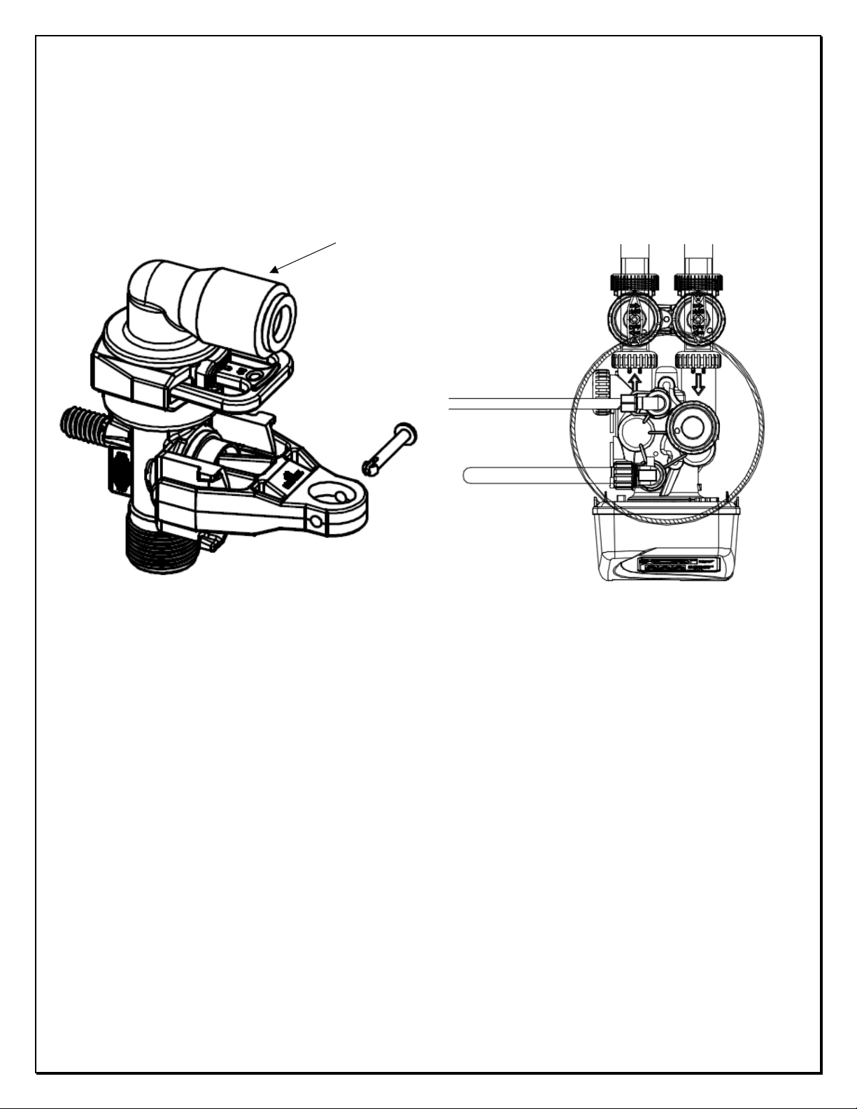
5) Components of Control Valve............................................................................................................. 19
5.1) Front Cover and PC Board...........................................................................................................19
5.2) Drive assembly, Piston and Spacer stack .................................................................................... 20
5.3) Injector Assembly........................................................................................................................ 21
5.4) Brine Tank Line Flow Control ...................................................................................................... 22
5.5) Drain Line Flow Control Assembly .............................................................................................. 23
5.6) Outlet Meter Assembly............................................................................................................... 24
5.7) Bypass Valve Components .......................................................................................................... 25
5.8) Installation Fitting Assemblies .................................................................................................... 26
6) Brine Tank Assembly........................................................................................................................... 28
7) Troubleshooting.................................................................................................................................. 29
7.1) Possible Error Codes ................................................................................................................... 29
7.2) Troubleshooting Procedures.......................................................................................................30
8) Quick Reference Guide ....................................................................................................................... 33
9) Warranty ............................................................................................................................................. 35

2
SOFTENER INSTALLATION AND USER GUIDE
BARRIE • ONTARIO • CANADA 705.733.8900 WWW.EXCALIBURWATER.COM
1) INSTALLATION
1.1) Pre-installation instructions
The cycle times, sequence of cycles, salt dose refill time and exchange capacity are preset to by
Excalibur. The dealer must guide the installer to change the values according to the hardness, day
override and time of regeneration.
WATER TEST
Hardness gpg
Iron ppm
pH number
Nitrates ppm
Manganese ppm
Sulphur yes/no
Total Dissolved Solids
1.2) General Installation and Service Warnings
•The softener is designed so that it can be installed easily with minor plumbing changes on
previous plumbing.
•The piping must be clamped properly and the weight of the plumbing must not be on the
softener.
•Do not use any kind of lubricant including silicone. A silicone based lubricant can be only used on
black O-Rings but not necessary.
•Do not use pipe dope or other sealant on plastic nuts and caps. Teflon tape must be used only on
NPT threads.
•The nuts and caps can be fastened and unfastened by hand or the plastic service wrench. Do not
use pipe wrench to tighten the caps and nuts.
1.3) Site Requirements
•Water Pressure: - 40-110 psi
•Water Temperature: - 40-110°F (4.4-43°C)
•Electrical- 115/120 V, 60Hz Uninterrupted Outlet
•Current required is 0.5 Amperes with plug-in transformer (dry locations only).
•The tank should be on a firm level surface

4
SOFTENER INSTALLATION AND USER GUIDE
BARRIE • ONTARIO • CANADA 705.733.8900 WWW.EXCALIBURWATER.COM
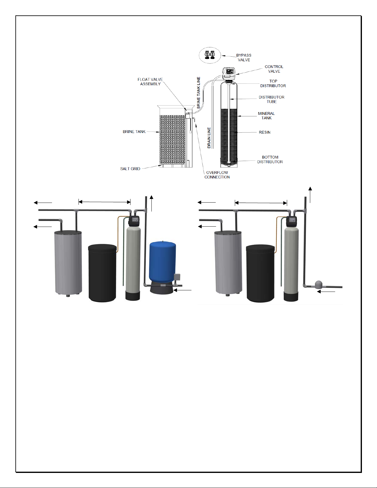
1.5) System Drawing
1.6) Plumbing Instructions
Well Water Installation Municipal Installation
1) The softener must be located at the closest possible location to drain.
2) The water heater’s inlet must be at least 10ft away from softener.
3) The unit including the drain must be located in a room temperature above 33° F.
4) If vacuum occurrence is expected then the vacuum breaker must be installed at the inlet of the
softener.
5) The bypass valve must be installed on the control valve.
6) The outside tap water if possible may be bypassed from the softener.
7) The primer, solder or solder flux must not get on the O-rings while installation.
8) After soldering the lines must be cooled before installing the O-Rings, nuts and caps.
9) If the electrical system is grounded to the plumbing, then a copper strap must be connected
between inlet and outlet as shown in figure above.
10) The plumbing must be done by following the local plumbing codes.
Water
heater
Pressure
Tank
Minimum 10ft
Water
Meter
Minimum 10ft
Brine
Tank
Brine
Tank
Outside
Tap
Outside
Tap
Water
heater
Cold
Cold
Hot
Hot
5
SOFTENER INSTALLATION AND USER GUIDE
BARRIE • ONTARIO • CANADA 705.733.8900 WWW.EXCALIBURWATER.COM
1.7) Brine Line Connection
Install 3/8” O.D. Polyethylene tube according to specification sheet from the brine tank to the control
valve.
1.8) Overflow Line Connection
•Only used where brine tank overflow water spillage can damage flooring or structure.
•Brine tank is equipped with safety float valve which prevents the overflow in case if control
valve fails to control the refill cycle.
•In case if safety float also fails to stop refill then only the water will come through overflow line
connection.
Tank Brine Line
Connection
Brine Line
Drain Line
6
SOFTENER INSTALLATION AND USER GUIDE
BARRIE • ONTARIO • CANADA 705.733.8900 WWW.EXCALIBURWATER.COM
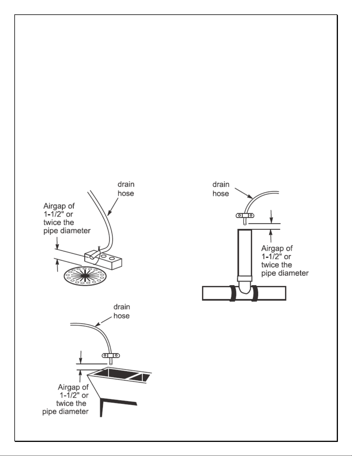
1.9) Drain Line
•The ½” tubing must be used for drain line.
•Leave minimum of 6” gap between flow control fitting and solder joints. The gap less than this
can damage the flow control.
•If the drain line is elevated and then emptied into the drain below the level the of control valve
then 7” loop should make at the end of drain line.
•The air gap between the drain and the end of the drain line must be twice the diameter of the
tube.
•The drain line must be clamped or strap tied at the end to secure in position.
7
SOFTENER INSTALLATION AND USER GUIDE
BARRIE • ONTARIO • CANADA 705.733.8900 WWW.EXCALIBURWATER.COM
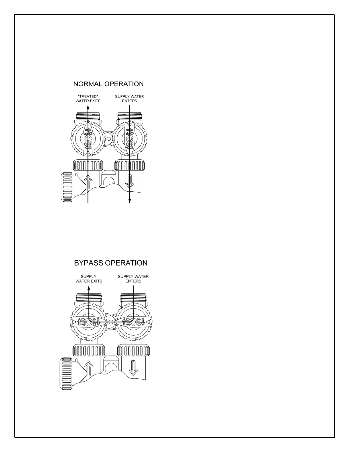
1.10) Bypass Valve
NORMAL OPERATION
The inlet and outlet handles of bypass valve should be
pointing the direction of flow indicated by the engraved
arrows on the control valve. Water flows through the
control valve in normal operation as a water softener.
BYPASS OPERATION
The inlet and outlet handles point to the center
of the bypass valve. The system is isolated from
the water pressure in the plumbing system.
Untreated water is supplied to the house in this
position.

8
SOFTENER INSTALLATION AND USER GUIDE
BARRIE • ONTARIO • CANADA 705.733.8900 WWW.EXCALIBURWATER.COM
DIAGNOSTIC MODE
The inlet handle points in the direction of flow and the
outlet handle points to the center of bypass valve,
system water pressure is allowed to the control valve
and the plumbing system while not allowing water to
exit from the control valve to the plumbing. Untreated
water is supplied to the house in this position.
SHUT OFF MODE
The inlet handle points to the center of the bypass
valve and the outlet handle points in the direction of
flow, the water is shut off to the plumbing system. If
water is available on the outlet side of the Softener, it
is an indication of water bypass around the system.

9
SOFTENER INSTALLATION AND USER GUIDE
BARRIE • ONTARIO • CANADA 705.733.8900 WWW.EXCALIBURWATER.COM
1.11) Start Up Instructions
•Keep the bypass valve in bypass operation by moving both handles pointing towards the center
of bypass valve. Now the untreated water is being supplied to house. Open the faucet
downstream of the softener until water comes clear out of it. The initial water can be dirty
because of installation debris. Now inspect the leaks in plumbing.
•Manually add approximate 6 inches of water to brine tank so that level reaches air check valve.
•Press and hold the “REGEN” button down for 5 seconds to start manual regeneration. The drive
motor will start to reach backwash cycle and countdown time begins. Turn the inlet bypass valve
handle halfway into the direction of diagnose operation. Once the steady water flows out of
drain then fully turn both handles of bypass valve into the direction of service operation.
Caution: - If water flow is too rapidly, there will be a loss of resin to drain.
•When the water become clear in drain line then press the regen button to advance the
regeneration to brine cycle. Lift off the brine tank lid to check if water is being drawn from brine
tank and shut off the faucet after confirming the brine draw flow.
•Press REGEN button to advance the regeneration to 2nd backwash cycle. Wait until the
countdown time starts.
•Press REGEN button again to advance the regeneration to rinse cycle with water coming through
the drain. Allow this process for the full amount of time during this cycle.
•The control valve will automatically advance the regeneration to the fill cycle. Allow to fill for the
full amount of time in this cycle. Once finished the control valve will automatically come to the
service position with the time of day being displayed.
•Add the salt to Brine Tank.
10
SOFTENER INSTALLATION AND USER GUIDE
BARRIE • ONTARIO • CANADA 705.733.8900 WWW.EXCALIBURWATER.COM
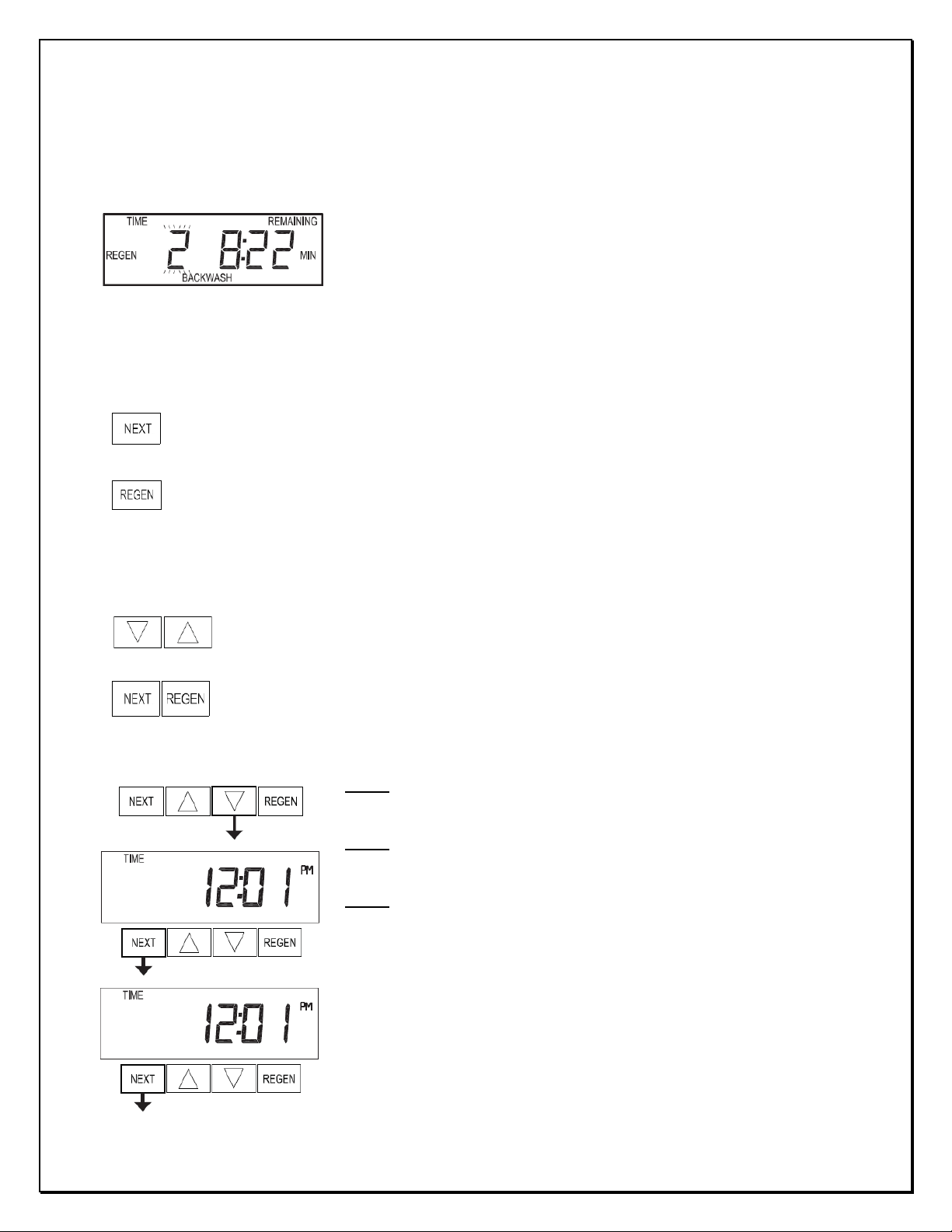
2) CONTROL VALVE PROGRAMMING
2.1) Regeneration Screens
2.2) Button Operation
2.3) Setting Time of Day
Regen Screen
•Displays the time remaining in the current cycle.
•Displays the cycle name and sequence number.
•Pressing REGEN advances to the next cycle.
Scrolls to the next display.
•Pressing once and releasing will schedule a regeneration at the preset delayed regeneration time.
•Pressing again and releasing will cancel the delayed regeneration.
•Pressing and holding for 3 seconds will initiate an immediate regeneration
•Pressing while in regeneration will advance to the next cycle.
•Pressing in the program levels will go backwards to the previous screen
Change Variable being displayed.
Holding for 3 seconds initiates a control reset. The software version is displayed and the
piston returns to the home/service position, resynchronizing the valve.
Step 1: - Push NEXT until time of day screen is displayed. Press and
hold ▼until SET TIME is displayed and the hour flashes once.
Step 2: - Press ▲or ▼until the correct hour is displayed. Then press
NEXT button.
Step 3: - The minutes will flash. Press ▲or ▼until the correct
minute is displayed. Press NEXT to return to the User Displays.
Time of day should only need to be set if: -
•power outage lasts more than 8 hours with good battery
•battery is depleted and power outage occurs
•when daylight saving time begins or ends.
Regeneration occurs automatically if volume capacity drops below the reserve capacity automatically
predicted by Control Valve or the has control valve reached 14 number of days since last regeneration.

11
SOFTENER INSTALLATION AND USER GUIDE
BARRIE • ONTARIO • CANADA 705.733.8900 WWW.EXCALIBURWATER.COM
2.4) User Displays
When the system is operating, one of five displays may be shown.
Pressing NEXT will alternate between the displays shown below.
User 1: - Shows volume remaining to next regeneration.
User 2: - Displays the number of days to next regeneration as per
time clock.
User 3: - Displays the current flow rate.
User 4: - Displays the total volume used.
User 5: - Shows current time of day.
Press NEXT to return to User Display 1
Return to User Display 1
12
SOFTENER INSTALLATION AND USER GUIDE
BARRIE • ONTARIO • CANADA 705.733.8900 WWW.EXCALIBURWATER.COM
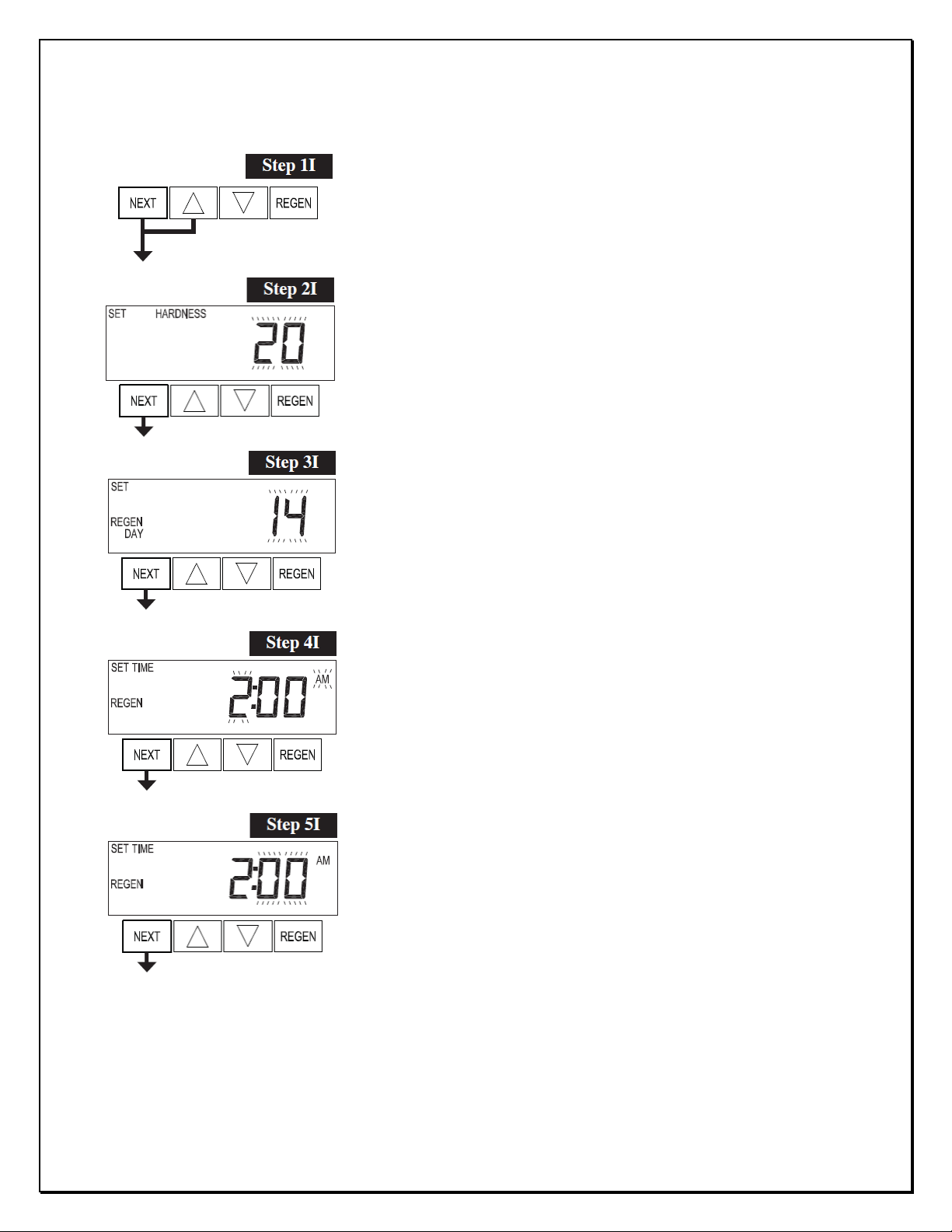
2.5) Installer Display Settings
Step 1I - To enter Installer Display press NEXT and ▲simultaneously
for about 5 seconds and release.
Step 2I – Hardness: Set the amount (gpg) of hardness using ▲or ▼.
Press NEXT to go to step 3I. Press REGEN to exit Installer Display
Settings.
Step 3I – Day Override: Set “14” the maximum number of days
between regenerations.
Press NEXT to go to step 4I. Press REGEN to return to previous step.
Step 4I – Next scheduled regeneration time (hour): Set the hour of
day for regeneration using ▲or ▼. (Usually 2:00AM or when the
predictable flow is minimum)
Press NEXT to go to step 5I. Press REGEN to return to previous step.
Step 5I – Next scheduled regeneration time (minutes): Set the
minutes of day for regeneration using ▲or ▼.
Press NEXT to exit Installer Display Settings. Press REGEN to return
to previous step.
EXIT INSTALLER DISPLAY SETTINGS

13
SOFTENER INSTALLATION AND USER GUIDE
BARRIE • ONTARIO • CANADA 705.733.8900 WWW.EXCALIBURWATER.COM
2.6) Configuration Settings
Step 1CS: - Press NEXT and ▼ simultaneously for 5 seconds and
release. Again press NEXT and ▼ simultaneously for 5 seconds.
Step 2CS: - Use to select “1.0” for 1in valve.
Note: - Do not select “1.0t”
Step 3CS: -Select “dPoFF” for softeners when no outside signal is
used for regeneration. Press NEXT to proceed to step 3CS or press
REGEN to go back to previous step.
Step 4CS: - Select “oFF” for standard
softeners and when no motorized
alternating valves are used. Press
NEXT to exit Configuration settings.
Exit Configuration Settings

14
SOFTENER INSTALLATION AND USER GUIDE
BARRIE • ONTARIO • CANADA 705.733.8900 WWW.EXCALIBURWATER.COM
2.7) Softener System Setup
Step 1S: - Press NEXT and ▼simultaneously for 5 seconds and
release.
Step 2S: - Choose “SOFTENING” using ▲or ▼.Press NEXT to go to
step 3S.
Step 3S: - Choose “dn” for downflow brining direction. Press NEXT to
go to step 4S or press REGEN to go back to previous step.
Step 4S: - Set “PoST” refill location to initiate refill cycle immediately
after rinse cycle.
Step 5S: - Select “6 min” duration for first backwash cycle. Press
NEXT to go to step 6S or press REGEN to go back to previous step.
Step 6S: - Select “60 min” duration for brine cycle. Press NEXT to go
to step 7S or press REGEN to go back to previous step.
Step 7S: - Select “4 min” for the 2nd backwash cycle. Press NEXT to
proceed to step 8S or press REGEN to return to previous step.
15
SOFTENER INSTALLATION AND USER GUIDE
BARRIE • ONTARIO • CANADA 705.733.8900 WWW.EXCALIBURWATER.COM
EXIT SOFTENER SYSTEM SETUP
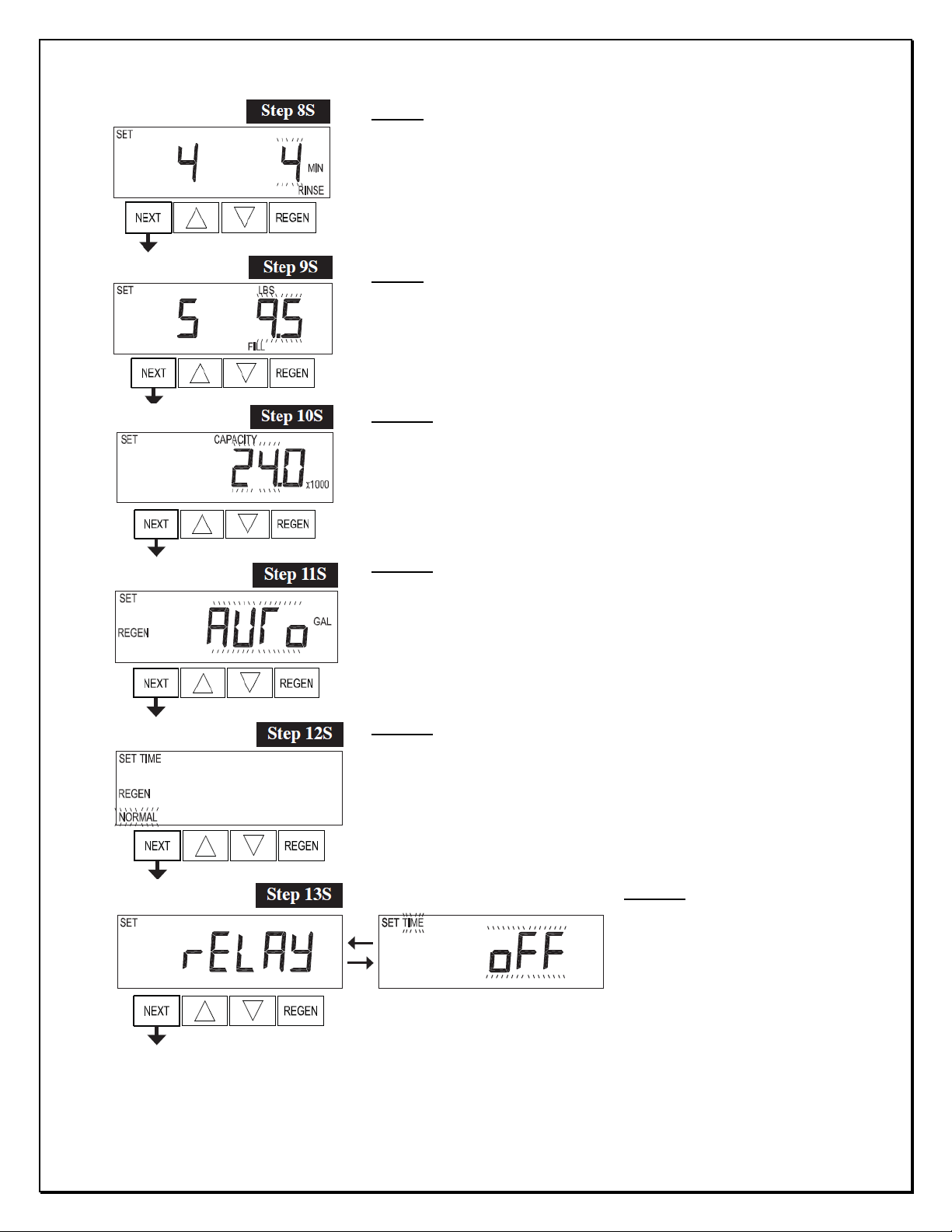
Step 8S: - Select “4 min” for the rinse cycle. Press NEXT to proceed
to step 9S or press REGEN to return to previous step.
Step 9S: - Select the salt dosage as per the performance data given.
Step 10S: - Set System Grains Capacity. Refer the performance table
given.
Step 11S: - Set “AUto” for automatic volume capacity and reserve
capacity calculations.
Step 12S: - Set “NORMAL” regeneration time so that regeneration
should occur only at preset time.
Step 13S: - Set relay operation “oFF”.
Press NEXT to exit softener system
setup or press REGEN to return to
previous step.
16
SOFTENER INSTALLATION AND USER GUIDE
BARRIE • ONTARIO • CANADA 705.733.8900 WWW.EXCALIBURWATER.COM
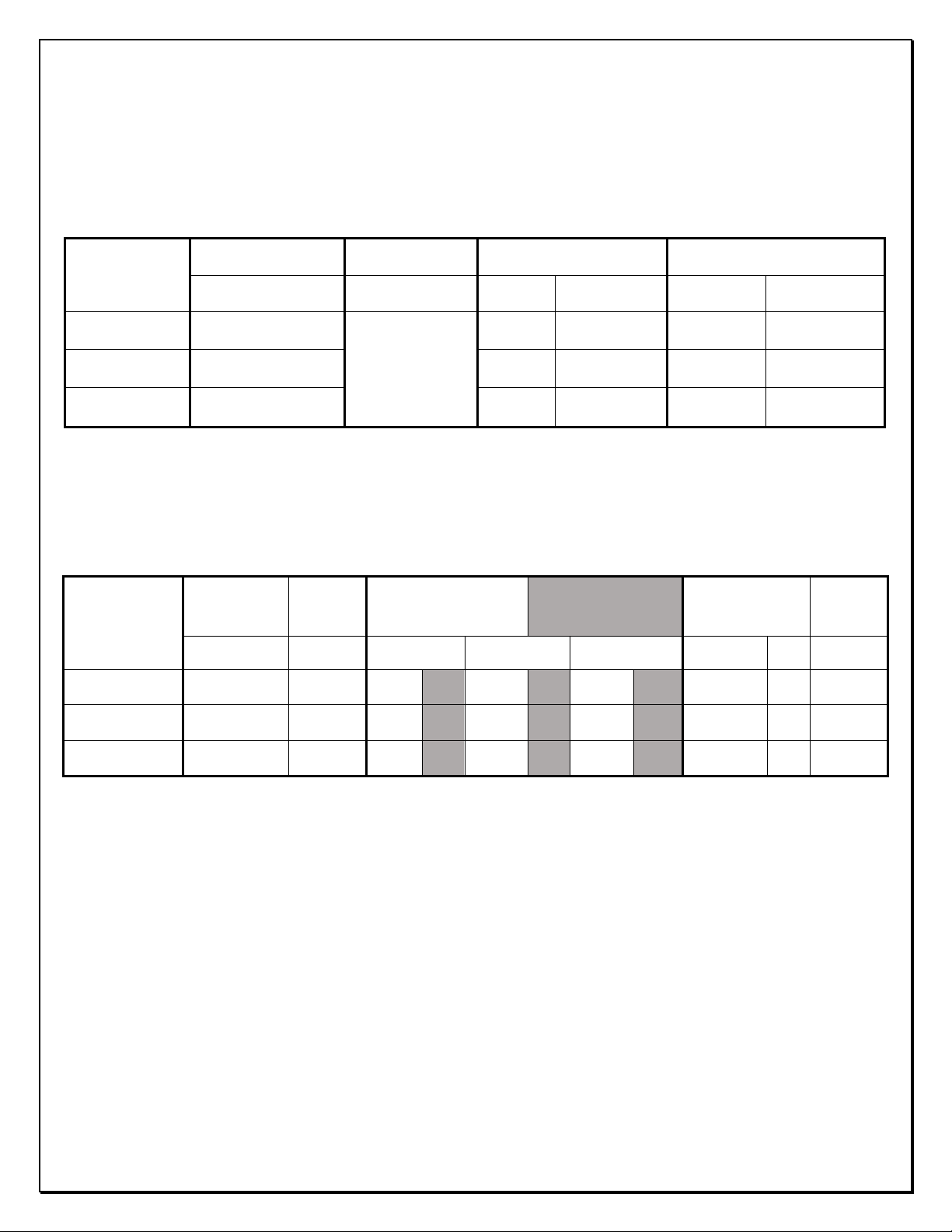
3) MODEL SPECIFICATIONS AND COMPONENTS
3.1) Flow Controls and Injectors
Model1
Number
Mineral Tank
Brine Tank
Injector Drain Flow Control
Dia X Height (Inch)
(Inch)
Color Order # Flow GPM Order #
EWS SUS24BF 9x48
18x33 (Dia x
Height)
Red CLK V30101D 1.3 CLK V3162013
EWS SUS34BF 10x54 White CLK V30101E 1.7 CLK V3162017
EWS SUS54BF 12x52 Blue CLK V30101F 2.2 CLK V3162022
3.2) Specifications
* Excalibur Softeners are factory programmed to 10lbs/ft3default settings
1 Sis only included in superior models and the given model numbers are for Ultimate superior softeners
Model1
Number
Mineral Tank Resin
Quantity Grains Capacity Lbs Salt Setting Flow (GPM) Shipping
Weight
Dia X Height ft36 lbs Salt/ft310 lbs Salt/ft3
15 lbs Salt/ft3
Continuous
Peak
LBS
EWS SUS24BF 9x48 1.0 20,000
6.0 27,000 10.0 30,000 15.0 4.0 6.4 74
EWS SUS34BF 10x54 1.5 30,000
9.0 40,500 15.0 45,000 22.5 5.7 9.0 95
EWS SUS54BF 12x52 2.0 40,000
12.0 54,000 20.0 60,000 30.0 9.0 14.4 161
17
SOFTENER INSTALLATION AND USER GUIDE
BARRIE • ONTARIO • CANADA 705.733.8900 WWW.EXCALIBURWATER.COM
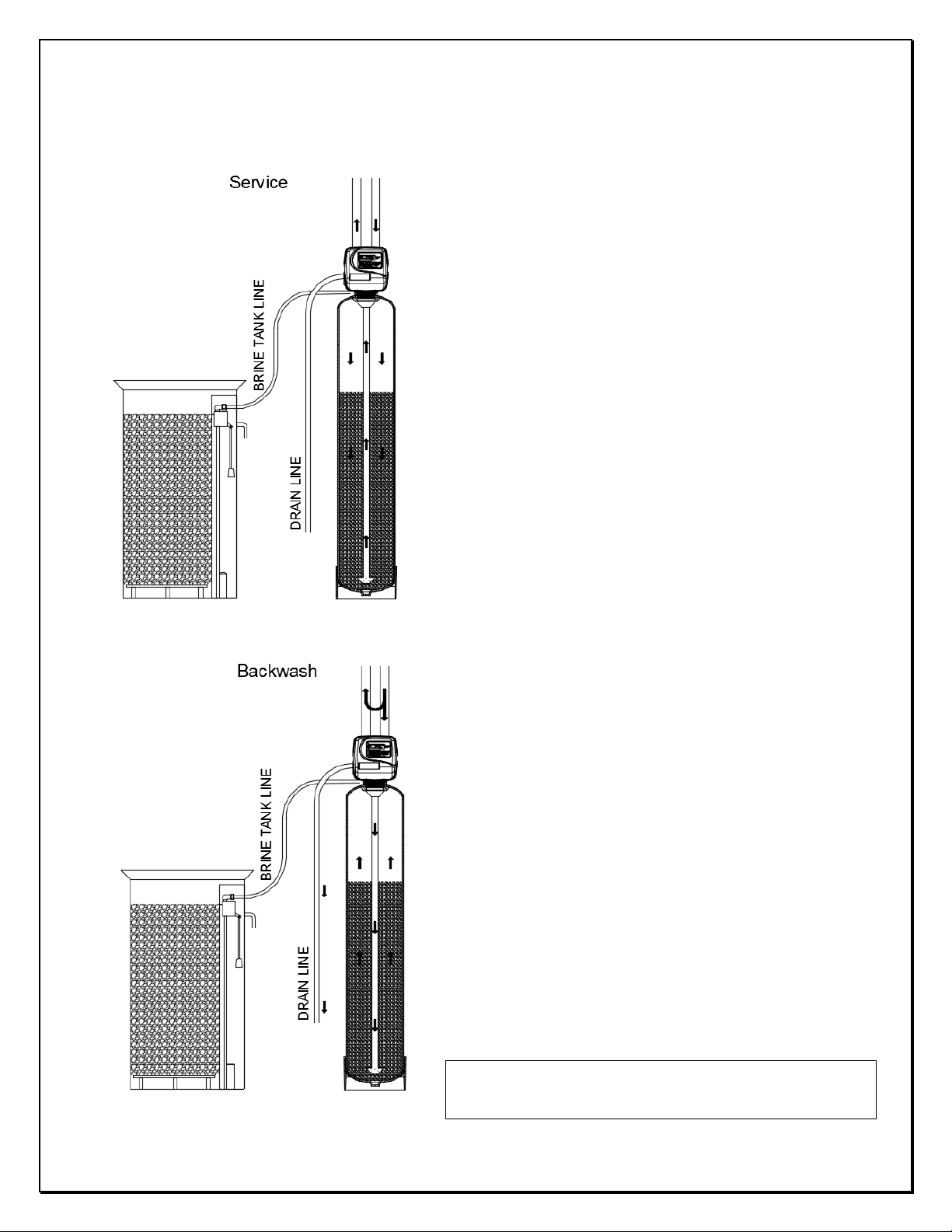
4) CONTROL VALVE CYCLES
In Service Cycle water flows through the upper basket
and flows down to the bottom distributor. In this
operation hardness of water is removed by resin.
In Backwash Cycle water flows in upflow direction, the
water enters the tank from bottom distributor and
collected by upper basket. This operation lifts the bed
and wash the resin. The water goes out through the
drain line.
Note: -Backwash, Brine and Rinse cycles bypass the
supply water to the demand.

18
SOFTENER INSTALLATION AND USER GUIDE
BARRIE • ONTARIO • CANADA 705.733.8900 WWW.EXCALIBURWATER.COM
In Brine Cycle water flows in downflow direction
which siphon the brine solution from brine tank and
slow rinse water goes to the drain.
In Rinse Cycle water flows rapidly in downflow
direction through the resin to the drain. This cycle
washes the excess sodium from the resin particles.
Fill Cycle (Not Shown): - The water flow same as
Service operation but water also flows to the brine
tank for refilling.
19
SOFTENER INSTALLATION AND USER GUIDE
BARRIE • ONTARIO • CANADA 705.733.8900 WWW.EXCALIBURWATER.COM
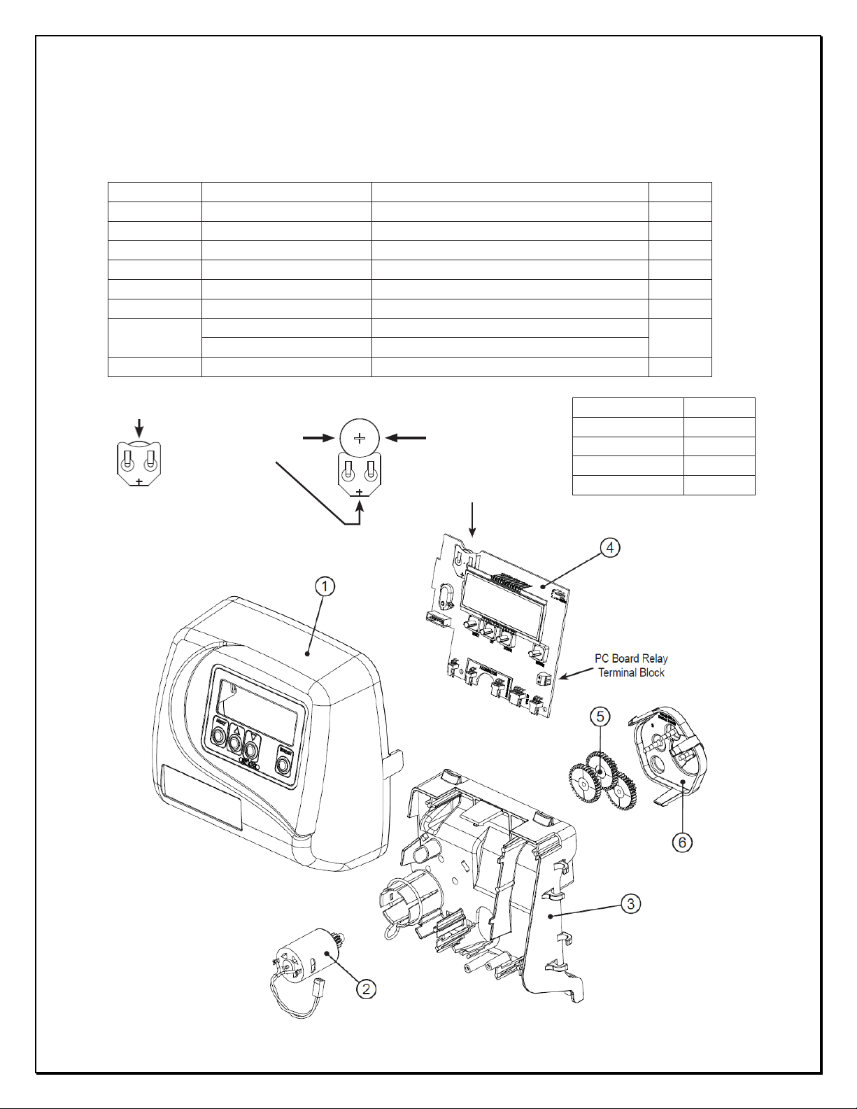
5) COMPONENTS OF CONTROL VALVE
5.1) Front Cover and PC Board
Drawing No.
Order No.
Description
Quantity
1
CLK V3175EE01
WS1EE FRONT COVER ASSEMBLY
1
2
CLK V310701
WS1 MOTOR
1
3
CLK V310601
WS1 DRIVE BRACKET & SPRING CLIP
1
4
CLK V3408EE04BOARD
WS1THRU/2 EE PCB 5 DIGIT REPL
1
5
CLK V3110
WS1 DRIVE GEAR 12X36
3
6
CLK V3109
WS1 DRIVE GEAR COVER
1
Not Shown
CLK V3186
WS1 AC ADAPTER 120V-12V
1
CLK V318601
WS1 AC ADAPTER CORD ONLY
Not Shown
CLK V3178
WS1 Drive Back Plate
1
AC Adapter
U.S.
Supply Voltage
120 V AC
Supply Frequency
60 Hz
Output Voltage
12 V AC
Output Current
500 mA
Battery fully seated
Correct
battery orientation
3 Volt lithium
coin cell type
2032
This manual suits for next models
2
Table of contents


