exemys GPS-MB User manual

GPS-110-MB-PS User’s ManualExemys
www.exemys.com Rev. 3 1

GPS-110-MB-PS User’s ManualExemys
www.exemys.com Rev. 3 2
Exemys Products are in constant evolution to satisfy our customer needs.
For that reason, the specifications and capabilities are subject to change without prior notice.
Updated information can be found at www.exemys.com
Copyright Exemys. All Rights Reserved.

GPS-110-MB-PS User’s ManualExemys
www.exemys.com Rev. 3 3
INDEX
INDEXINDEX
INDEX
INDEX _______________________________________________________________ 3
1 INTRODUCTION ______________________________________________________ 5
1.1 Purpose of the manual ________________________________________________ 5
1.2 Product Overview ____________________________________________________ 5
1.3
1.31.3
1.3 Ordering Codes
Ordering CodesOrdering Codes
Ordering Codes _______________________________________________________ 5
1.4
1.41.4
1.4 Technical Specifications
Technical SpecificationsTechnical Specifications
Technical Specifications ________________________________________________ 6
2 INSTALLATION _______________________________________________________ 7
2.1 Connecting the power supply __________________________________________ 7
2.2 erial Port Wirings ___________________________________________________ 7
2.2.1 RS232 port wiring _________________________________________________________ 8
2.2.2 RS485 port wiring _________________________________________________________ 8
2.3 LEDs indicators ______________________________________________________ 9
2.4 Antenna Connector __________________________________________________ 9
3 CONFIGURATION ____________________________________________________ 10
3.1 Port A Configuration- NMEA. __________________________________________ 11
3.2 Port B Configuration-Modbus. _________________________________________ 12
3.3 Other configuration settings. __________________________________________ 13
4 MODBUS REGISTERS _________________________________________________ 14
A.FACTORY SETTINGS __________________________________________________ 16
B.DIN RAIL MOUNTING ________________________________________________ 17

GPS-110-MB-PS User’s ManualExemys
www.exemys.com Rev. 3 4
GPS-110-MB-PS User’s ManualExemys
www.exemys.com Rev. 3
1
11
1I
II
INTRODUCTION
NTRODUCTIONNTRODUCTION
NTRODUCTION
1.1
1.11.1
1.1 Purpose of the manual
Purpose of the manualPurpose of the manual
Purpose of the manual
This manual provides the instructions for easy and quick installing and operating of the GPS-
110-MB-PS. The manual starts with a general description of the product, following the
instructions for the correct hardware installation. Configuration and operation of the device
is detailed below.
1.2
1.21.2
1.2 Product Overview
Product OverviewProduct Overview
Product Overview
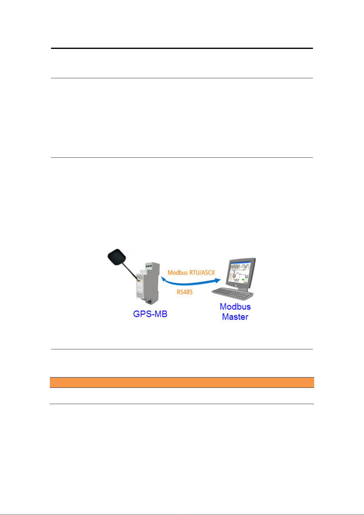
GPS-110-MB-PS is a GPS with Modbus communication (slave).
GPS-110-MB-PS has two series ports, one RS232 for configuration and reading of NMEA
sentences, and one RS485 to function as a Modbus slave.
All the data generated by the GPS (Latitude, Longitude, Speed, Time) are available in Modbus
registers in its slave port.
1.3
1.31.3
1.3 Ordering Codes
Ordering CodesOrdering Codes
Ordering Codes
The complete product ordering codes are:
Ordering Code Description
Ordering Code DescriptionOrdering Code Description
Ordering Code Description
G
GG
GPS
PSPS
PS-
--
-110
110110
110-
--
-MB
MBMB
MB-
--
-PS
PSPS
PS
(1) Serial Port RS-232
(1) Serial Port RS-485

GPS-110-MB-PS User’s ManualExemys
www.exemys.com Rev. 3 6
1.4
1.41.4
1.4 Technical Specifications
Technical SpecificationsTechnical Specifications
Technical Specifications
Technical Specification
Technical SpecificationTechnical Specification
Technical Specification
Communication Pr
Communication PrCommunication Pr
Communication Protocols
otocolsotocols
otocols
Modbus RTU, Modbus ASCII, NMEA 0183.
Serial Port
Serial PortSerial Port
Serial Port
1 RS232+1RS485 on Terminal Block connection.
Device Management
Device ManagementDevice Management
Device Management
RS-232 Serial Console.
LED Indica
LED IndicaLED Indica
LED Indicators
torstors
tors
GPS data, Modbus data.
GPS
GPSGPS
GPS
Data
DataData
Data
GPS, Galileo, Glonass
Time for first cold data: 35 sec. typical
Update speed: 1 second
Accuracy: 3 ms for position, 0.1m / s for speed
Sensitivity
• Acquisition: -148dBm, cold start
• Re-acquisition: -163dBm, warm start
• Tracking: -165dBm
SMA connector for active external antenna
GPS
GPSGPS
GPS
Antenna
AntennaAntenna
Antenna
Active with magnetic anchor
SMA connector
IP67 protection
3 meters of cable
Measurements
MeasurementsMeasurements
Measurements
90 mm x 12,5 mm x 57 mm (Height x Width x Length)
(without antenna connector)
Power Supply
Power SupplyPower Supply
Power Supply
10 to 30 VDC
Consumption
ConsumptionConsumption
Consumption
12VDC 26mA/ 24VDC 18mA
Temperatures
TemperaturesTemperatures
Temperatures
Operation Temperature: -15°C to 65 °C
Storage Temperature: -40°C to 75 °C
Warranty
WarrantyWarranty
Warranty
1 Year
Technical Support Included
GPS-110-MB-PS User’s ManualExemys
www.exemys.com Rev. 3 7
2
22
2I
II
INSTALLATION
NSTALLATIONNSTALLATION
NSTALLATION
2.1
2.12.1
2.1 Connecting the power supply
Connecting the power supplyConnecting the power supply
Connecting the power supply
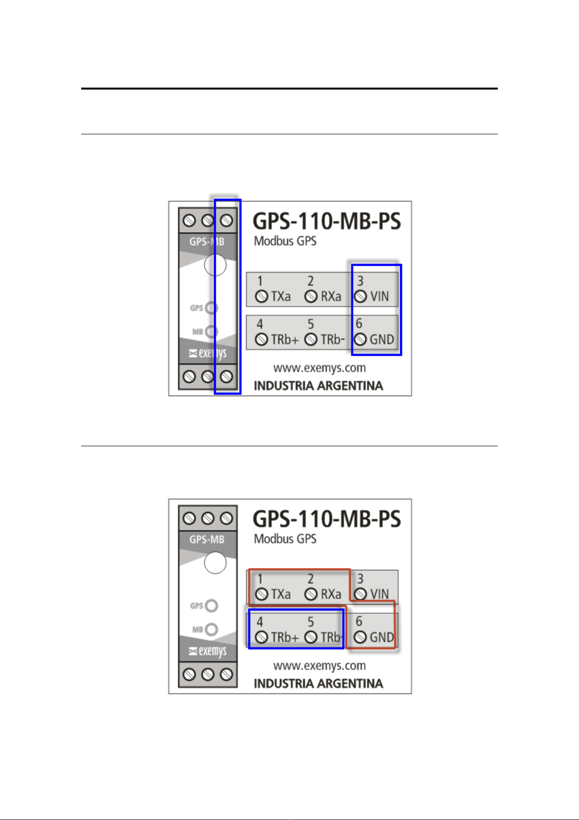
GPS-110-MB-PS allows a power supply from +10 to 30 VDC. Positive power supply must be
connected to terminal N° 3 and negative power supply to terminal No. 6 as shown in the
following figure:
2.2
2.22.2
2.2 Serial Port Wirings
Serial Port WiringsSerial Port Wirings
Serial Port Wirings
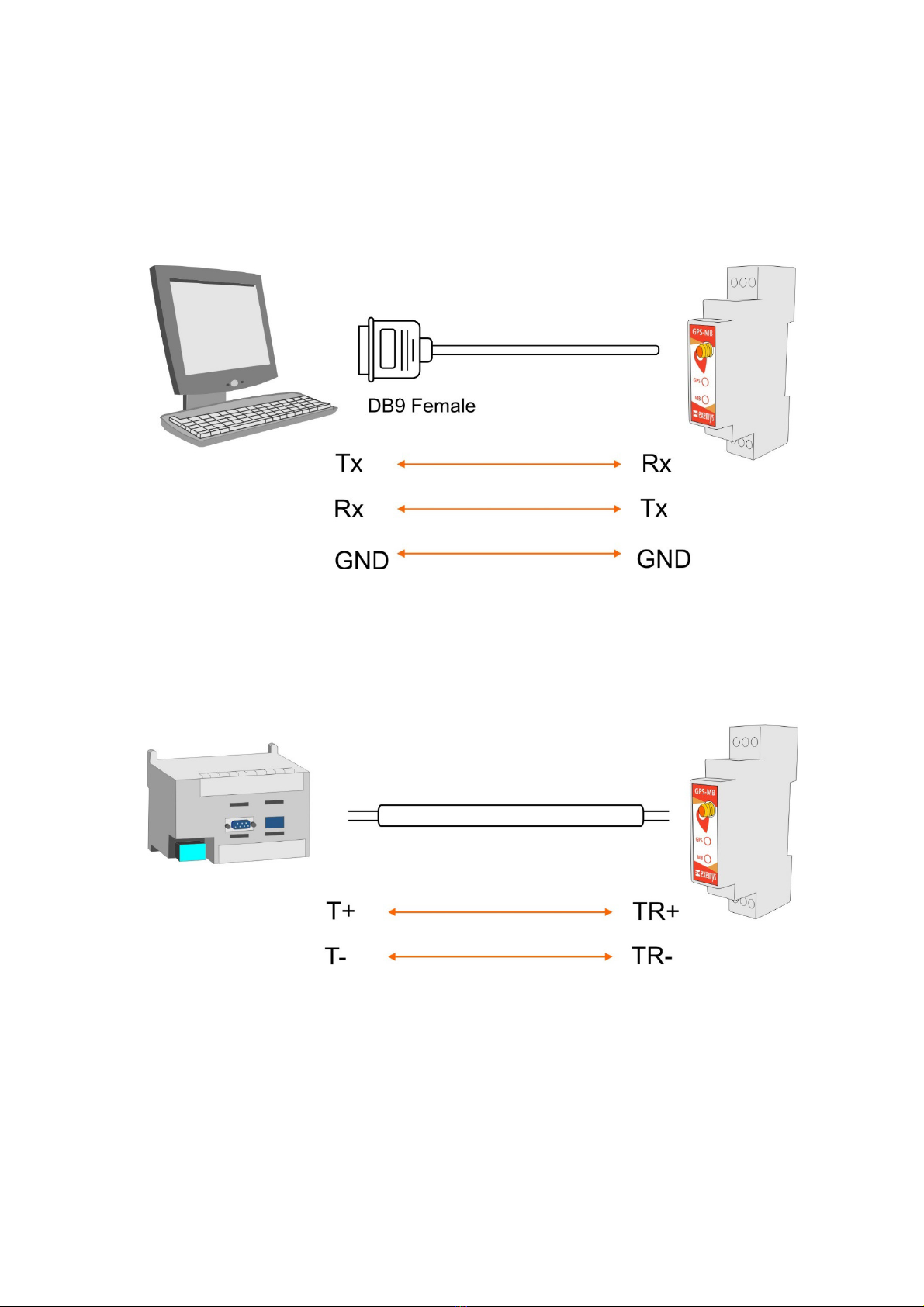
GPS-110-MB-PShas twoserial ports; one of them is RS232 (Port A), used for configuration
and monitoring, and other one RS485 (Port B) for MODBUS.
GPS-110-MB-PS User’s ManualExemys
www.exemys.com Rev. 3 8
2.2.1
2.2.12.2.1
2.2.1 RS232
RS232RS232
RS232
port wiring
port wiringport wiring
port wiring
To connect the device RS232 serial port to PC serial port or any other serial device to set and
monitor, it must be connected as can be shown in the following figure. You should consider
GPS-110-MB-PS is a DTE device, that means it must cross wire with those of the PC.
2.2.2
2.2.22.2.2
2.2.2 RS485
RS485RS485
RS485
port wiring
port wiringport wiring
port wiring
To connect the device RS485 serial port to any serial device, it must be connected as can be
shown in the following figure.

GPS-110-MB-PS User’s ManualExemys
www.exemys.com Rev. 3 9
2.3
2.32.3
2.3 L
LL
L D
DD
Ds indicators
s indicatorss indicators
s indicators
GPS-110-MB-PShas two LEDS indicators.
LED“GPS”
Permanently ON if there is no GPS signal.
Flashes when there is a GPS signal.
It also indicates the first seconds to send a configuration.
LED “MB”
Permanently ON if there are no Modbus queries.
Flashes every time you receive a valid Modbus query.
2.4
2.42.4
2.4 A
AA
Anten
ntennten
ntenn
nn
na
aa
a
Connector
ConnectorConnector
Connector
Device has an SMA connector on the front to connect an active external GPS antenna.
An active antenna with magnetic mounting and 3 meters of cable with SMA connector is
provided with the device.

GPS-110-MB-PS User’s Manual
Exemys
www.exemys.com
3
33
3C
CC
C
ONFIGURATION
ONFIGURATIONONFIGURATION
ONFIGURATION
GPS-110-MB-
PS configuration is done through a command console connecting the device to a
RS232 port on the PC.
To access the co
mmand console, you must connect the GPS
PC and you must install an Exemys serial terminal program, named
Download the Exemys Console:
http://www.exemys.com/console
Once the serial terminal program is installed, connect the GPS
the PC and execute the
Exemys Console
1.
Click on Connection
port. Select with double click the po
the serial port
is 9600.
2. Turn on the GPS-
110
press the CFG button.
configuration command
Exemys
Rev. 3
ONFIGURATION
ONFIGURATIONONFIGURATION
ONFIGURATION
PS configuration is done through a command console connecting the device to a
mmand console, you must connect the GPS
-110-MB-
PS to a RS232 port on a
PC and you must install an Exemys serial terminal program, named
Exemys Console.
Download the Exemys Console:
http://www.exemys.com/console
Once the serial terminal program is installed, connect the GPS
-110-MB-
PS to a RS232 port on
Exemys Console
.
Click on Connection
-
> Serial Port, it will open a window with name of all COM Serial
port. Select with double click the po
rt where device is connected. Verify Baud rate in
is 9600.
110
-MB-PS
and in the first 7 seconds type CFG and press ENTER or
press the CFG button.
GPS-110-MB-PS
will display a welcome message on the
configuration command
console.
10
PS configuration is done through a command console connecting the device to a
PS to a RS232 port on a
Exemys Console.
PS to a RS232 port on
> Serial Port, it will open a window with name of all COM Serial
rt where device is connected. Verify Baud rate in
and in the first 7 seconds type CFG and press ENTER or
will display a welcome message on the

GPS-110-MB-PS User’s ManualExemys
www.exemys.com Rev. 3 11
3. Type the commands which you want to edit its parameters with the proposed values.
4. To finish and save all the changes, type the command 5
55
5 (END), after which device
will restart and return to normal operation.
3.1
3.13.1
3.1 Po
PoPo
Port A
rt A rt A
rt A Configuration
ConfigurationConfiguration
Configuration-
--
-
NM A.
NM A.NM A.
NM A.
Port A (RS232) can be used to monitor the internal GPS operation by seeing the NMEA
sentences that the GPS sends. You can ignore this section if you are not going to use port A
NMEA (RS 232).
Com
m
and
Descrip
tion
(1)-> 1
Baud Rate
(1200|…|115200)
Setting the baud rate of the Serial Port A.
•Values: 1200, 2400, 4800, 9600, 14400, 19200, 28800, 38400, 57600 or
115200.
Example of use: 1->1->8: 115200 bps
(1)-> 2
Data Bits
(7|8)
Setting the data bits of the Serial Port A.
• Values: 7 or 8.
Example of use:1->2->1: 7 Data bits
(1)-> 3
Parity
(N|E|O)
Setting the parity of the port A
•Values: None, Even, Odd
Example of use:1->3->2: Even parity
(1)-> 4
Parse
(E|D)
Enables the interpretation of the sentences in port A.
• Disabled: The NMEA frames are displayed as they come from the GPS.
• Enabled: The NMEA sentences are decoded for a simple reading of the user.
Example of use: 1->4->1: Interpretation Enable

GPS-110-MB-PS User’s ManualExemys
www.exemys.com Rev. 3 12
3.2
3.23.2
3.2 Port
PortPort
Port
B
B B
B Configuration
ConfigurationConfiguration
Configuration-
--
-Modbus
ModbusModbus
Modbus.
..
.
Com
m
and
Descrip
tion
(2)-> 1
Baud Rate
(1200|…|115200)
Setting the baud rate of the Serial Port B.
•Values: 1200, 2400, 4800, 9600, 14400, 19200, 28800, 38400, 57600 or 115200.
Example of use: 2->1->4: 9600 bps
(2)-> 2
Data Bits
(7|8)
Setting the data bits of the Serial Port B.
• Values: 7 or 8.
Example of use: 2->2->2: 8 Data bits
(2)-> 3
Parity
(N|E|O)
Setting the parity of the port B
•Values: None, Even, Odd
Example of use: 2->3->3: Odd parity
(2)-> 4
Protocol
(R|A)
Setting the protocol communication of the port B
•Values: RTU orASCII.
Example of use: 2->4->1: Modbus RTU
(2)->5
RTU
PacketTimeOut
(3..50)
Modbus RTU packet time out for the port B
•Values: 3 to 50 [Bytes Time].
Example of use:2->4->10: Time Out 10
(2)-> 6
Exceptions
(E|D)
Enable or Disable the exceptions for the port B.
•Values:Enable, Disable.
Example of use:2->6->1: Exceptions Enable
(2)-> 7
Modbus Slave
ID
(1...254)
Setting the slave ID to access the Modbus register memory.
•Values: 1 to 254.
Example of use:2->7->88:Modbus Slave ID 88
RTU PAC
RTU PACRTU PAC
RTU PACK
KK
KE
EE
ETT
TTTT
TTIME
IME IME
IME OUT
OUTOUT
OUT-
--
-
Modbus RTU packet time out: Modbus RTU packets are separated
from each other by a time interval. This parameter allows you to change the maximum time to
count after the last byte of the packet is received, during which the GPS-110-MB-PS will
assume that the packet has not yet been terminated. After this maximum time, the GPS-110-
MB-PS will assume that the packet has finished arriving. The time is entered in one-byte time
units, with a minimum of 3 units.
EXCEPTION
EXCEPTIONEXCEPTION
EXCEPTIONS
SS
S- Enables or disables exceptions for the Modbus Port. If the option is disabled the
GPS-110-MB-PS will respond to errors with silence, otherwise it will return an exception code.
NOTE:
NOTE:NOTE:
NOTE: Stop bits are fixed at 1 in both ports

GPS-110-MB-PS User’s ManualExemys
www.exemys.com Rev. 3 13
3.3
3.33.3
3.3 O
OO
Other configuration settings.
ther configuration settings.ther configuration settings.
ther configuration settings.
Command Description
3
Show
Configuration
Request the current device configuration.
4
Factory Reset
Reset to the factory settings.
This command must be entered 2 times for this to begin
working.
5
END
It saves the changes made and it ends the command console.

GPS-110-MB-PS User’s ManualExemys
www.exemys.com Rev. 3 14
4
44
4MODBUS REGISTERS
MODBUS REGISTERSMODBUS REGISTERS
MODBUS REGISTERS
If there is no GPS signal some registers will get value 0.
Main Registers
40001:2 Latitude x10.000.000 signed º
40003:4 Longitude x10.000.000 signed º
40005:6 Altitude x10 meters
40007 Geoidal separation x10 meters
40008 True course x10 º
40010 Magnetic variation x10 º
40011 Speed x10 kph
40012 Speed over ground x10 kph
40013 GPS Quality - -
40014 Number of satellites in view - -
40015 Age of differential GPS data x10 seconds
40016 Horizontal Dilution of precision x10 -
40017:18 UTC Date ddmmyyyy -
40019:20 UTC Time hhmmss -
40021 State (A: active / V: no signal) ASCII -
40022 Mode [A: Autonomous / D: Differential/ E:
Estimated] ASCII -
Alternative Registers
40050 Latitude–Degrees - -
40051 Latitude– Minutes - -
40052:53 Latitude–Minutes fraction 7 digits -
40054 Longitude–Degrees - -
40055 Longitude–Minutes - -
40056:57 Longitude - Minutes fraction 7 digits -
40058:59 Altitude x10 feet
40060 Geoidal separation x10 feet
40061 Speed x10 knot
40062 Speed over ground x10 knot
40063:64 UTC Date + UTC Time Seconds since 1970 seconds
40065:66 UTC Time Seconds since12:00 AM seconds
40067 Time hh -
40068 Minutes mm -
40069 Seconds ss -
40070 Day dd -
40071 Month mm -
40072 Year yyyy -
40073 State [active / no signal] 1 o 0 -
40074 Mode [A: Autonomous / D: Differential/ E:
Estimated] 0 o 1 o 2 -

GPS-110-MB-PS User’s ManualExemys
www.exemys.com Rev. 3 1
Clarification
ClarificationClarification
Clarification:
::
:
•Where there are two Modbus registers is to represent a 32-bit signed integer value, the first
register contains the lower part and the second the upper part of the value.
• Where "x10" is specified, it means that the value obtained from the GPS is multiplied by
the corresponding factor to achieve a higher degree of resolution in the indicated value.
• Where "ASCII" is specified, it means that the value read is the numeric representation
according to the ASCII coding of the letter obtained from the GPS
• Where "ddmmyyyy" is specified, it means that in the value, 2 digits represent the day, 2
the month and 4 the year. Thus, the number 15112019, refers to the date November 15,
2019.
• Where "hhmmss" is specified, it means that in the value, 2 digits represent the hour, 2 the
minutes and 2 the seconds. Thus, the decimal number 123045, refers to the time 12:30:45.
• In the registers where the Latitude and Longitude are expressed, the value is presented in
degrees multiplied by 10,000,000.
For example, if the register value is -
--
-346.054.585
346.054.585346.054.585
346.054.585, you must divide it by 10.000.000 to take
the format degrees
format degreesformat degrees
format degrees.
Then it becomes-
--
-34,6054585
34,605458534,6054585
34,6054585°
°°
°
To take it to the degrees + minutes format
degrees + minutes formatdegrees + minutes format
degrees + minutes format, you must multiply the decimal part of the
degrees by 60'. In this case 0.6054585 x 60 'equals 36.32751'.
Then it becomes-
--
-34
3434
34°
° °
° 36,32751'
36,32751'36,32751'
36,32751'
To take it to the degrees + minutes + seconds
degrees + minutes + seconds degrees + minutes + seconds
degrees + minutes + seconds format
formatformat
format, you must multiply the decimal part of
the minutes by 60’'. In this case 0.32751 x 60 "equals 19.6506".
Then it becomes-
--
-34
3434
34°
° °
° 36'19,6506 "
36'19,6506 "36'19,6506 "
36'19,6506 "
• In the alternative Latitude and Longitude format, grade and minutes are represented in two
registers and the decimal part of the minutes in another register with 7 digits.
For the previous example with -
--
-34
3434
34°
° °
° 36,32751'
36,32751'36,32751'
36,32751'it is represented in 3 registers
-34 (with grades)
36 (with the minutes)
3275100 (the decimal part of the minutes with 7 digits)
Easy online calculation is available at www.exemys.com/gpsconverter

GPS-110-MB-PS User’s ManualExemys
www.exemys.com Rev. 3 16
A
AA
A.
..
.FACTORY SETTINGS
FACTORY SETTINGSFACTORY SETTINGS
FACTORY SETTINGS
Par
ameter
Val
ue
P
PP
P
o
oo
o
rt
rt rt
rt
A
A A
A
-
--
-
NMEA
NMEA NMEA
NMEA
-
--
-
RS232
RS232RS232
RS232
Baud Rate
9600 bps
Data Bits
8
Pari
ty
NO
NE
Interpreta
tion
NMEA
D
isable
P
PP
P
o
oo
o
rt
rt rt
rt
B
B B
B
–
––
–
MODBUS
MODBUSMODBUS
MODBUS
–
––
–
RS485
RS485RS485
RS485
Baud Rate
9600 bps
Data Bits
8
Pari
ty
NO
Protocol
Modbus
RTU
Modbus RTU packet time
3
[
byte
s Time]
Excep
tions
D
isable
Modbus Slave ID
240

GPS-110-MB-PS User’s ManualExemys
www.exemys.com Rev. 3 17
B
BB
B.
..
.DIN RAIL MOUNTING
DIN RAIL MOUNTINGDIN RAIL MOUNTING
DIN RAIL MOUNTING
Device can be mounted on a DIN rail. To assembly the module to the rail, make the upper
side of the device fit the DIN rail and then push gently until you hear a Click! As shown in the
figure.
To disassemble the device of the rail DIN, pull down the metallic clip and then remove it as
shown in the figure.
This manual suits for next models
1
Table of contents


 instruction manual")


