Exmark Ultra Vac QDS Frontrunner FRCK524 Manual

Page 1 of 7
109-6609 Rev. C
Loose Parts shipped inside Hopper:
109-6603 Dealer Pack
Part # Description Qty Use
103-1309 Warranty Registration Form 1 Fill out and return to Exmark
109-5606 Decal, Door Operation 1 Install on Lower ROPS Tube
109-3458 Pin, Chute Pivot 1 Used to retain discharge chute for side discharge
1-806003 Pin, Chute Pivot Hairpin 1 Retains chute pivot pin to deck
109-6474 Fill Sensor Harness Pack
Part # Description Qty Use
109-5340 Harness, Tractor Fill Sensor 1 Fill Sensor wiring harness with alarm attached
1-303335 Tie,7-15/16” Plastic 4 To retain Tractor Harness to tractor
109-5304-03 Bracket, Alarm Mtg 1 Bracket to hold Fill Sensor Alarm
109-2394
3290-357 U-bolt
3/8”-6 Whizlock Nut 1
2 To retain alarm bracket to ROPS
6x9 Hardware Bag
Part # Description Qty Use
323-9
3290-357
98-5975
Screw, 3/8-16 x 1-3/4” Hex
Nut, Whizlock 3/8
Washer, Spring Disc 3/8 4 To attach lower frame mount to frame
109-6604 Literature Pack
Part # Description Qty Use
-----------
----------- Manual, Operator’s
Manual, Parts 1
1 Read before operating machine
Model Numbers
FRUVD – Fits FrontRunner with 52”, 60” or 72” deck
FRCK524 – Completing kit for 52” deck
FRCK604 – Completing kit for 60” deck
FRCK724 – Completing kit for 72” deck
Note: Dual tail wheels are REQUIRED for maximum stability, clearance, and capacity.
FRDTWK – Complete kit to install dual tail wheels.
FRDTWA – Partial kit to install dual tail wheels, re-uses some components from single tailwheel.
FRONTRUNNER
®
ULTRA VAC
SETUP INSTRUCTIONS
For Serial Nos. 670,000 and Highe
r
Page 2 of 7
109-6609 Rev. C
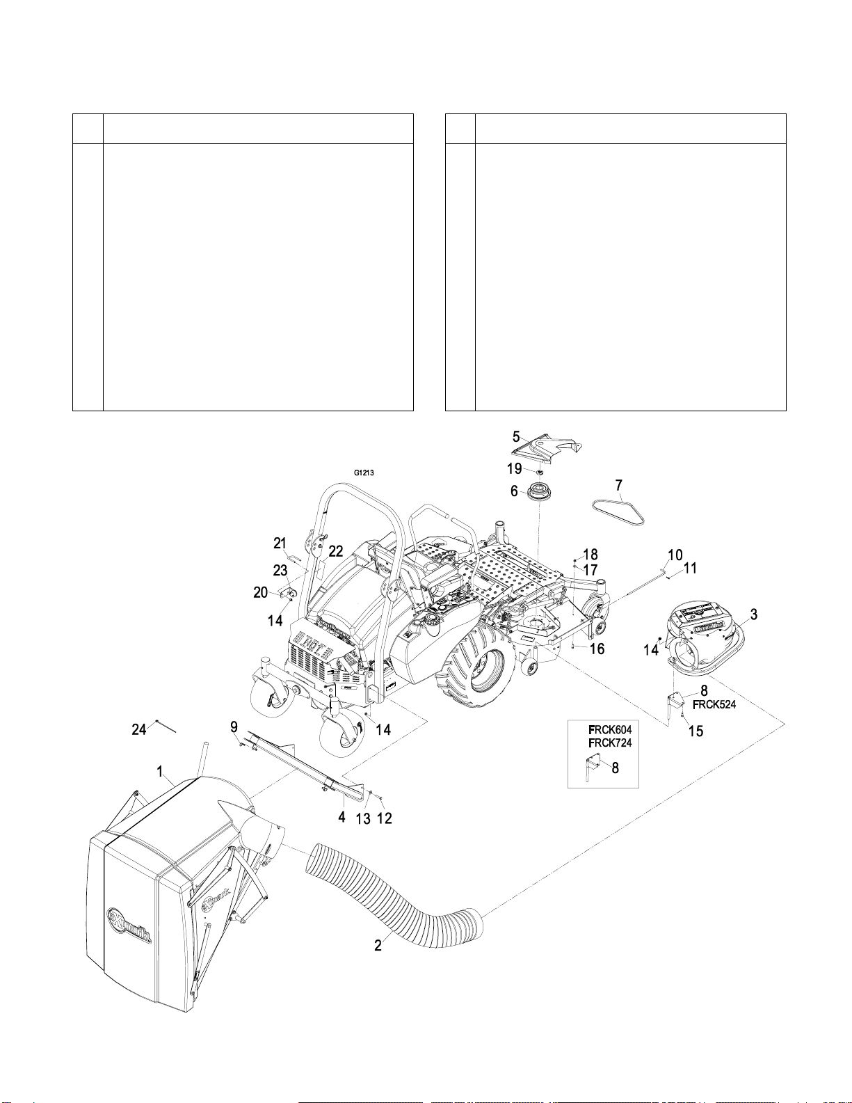
1. Assembly Instructions
Item
Part No.
Description
Qty.
1 ------------ Asm, Hopper..........................................1
2 ------------ Hose, FRUVD........................................1
3 ------------ Asm, Blower...........................................1
4 109-4748-03 Wld, Hopper Support..............................1
5 109-4846 Cover, Belt 52".......................................1
109-4847 Cover, Belt 60".......................................1
109-4848 Cover, Belt 72”.......................................1
6 103-2797 Jackshaft, 52" ........................................1
103-2792 Jackshaft, 60" ........................................1
109-2796 Jackshaft 72” .........................................1
7 109-4948 Belt, Blower Drive 52" ............................1
103-0866 Belt, Blower Drive 60" ............................1
103-0867 Belt, Blower Drive 72” ............................1
8 109-4841-03 Wld, Mount Pin 52" ................................1
103-0445-03 Wld, Mount Pin 60" & 72”.......................1
9 1-806005 Hairpin, Cotter (large).............................2
Item
Part No.
Description
Qty.
10 109-3458 Pin, Chute Pivot..................................... 1
11 1-806003 Pin, Hair (small).....................................1
12 323-9 Screw, HH 3/8-16 x 1 3/4....................... 4
13 98-5975 Washer, Spring Disk 3/8........................ 4
14 3290-357 Nut, Whizlock 3/8-16..............................9
15 323-4 Screw, HH 3/8-16 x 3/4..........................3
16 322-5 Screw, HH 5/16-18 x 1...........................1
17 3256-3 Washer, 5/16 Std................................... 1
18 32128-20 Nut, Whizlock 5/16-18............................ 1
19 103-1279 Plug.......................................................1
20 109-5304-03 Bracket, Alarm....................................... 1
21 109-2394 U-bolt..................................................... 1
22 109-5606 Decal, Door Operation........................... 1
23 ------------ Harness, Alarm...................................... 1
24 1-303335 Ties, Zip ................................................4
FIGURE 1
Page 3 of 7
109-6609 Rev. C
Safety
Safety Alert Symbol
This SAFETY ALERT SYMBOL is used
both in this instruction sheet and on the machine
to identify important safety messages which must
be followed to avoid accidents. This symbol
means:
ATTENTION! BECOME ALERT!
YOUR SAFETY IS INVOLVED!
The safety alert symbol appears above information
which alerts you to unsafe actions or situations and
will be followed by the word DANGER, WARNING,
or CAUTION.
DANGER: White lettering / Red background.
Indicates an imminently hazardous situation which,
if not avoided, WILL result in death or serious injury.
WARNING: Black lettering / Orange background.
Indicates a potentially hazardous situation which, if
not avoided, COULD result in death or serious
injury.
CAUTION: Black lettering / Yellow background.
Indicates a potentially hazardous situation which, if
not avoided, MAY result in minor or moderate injury.
WARNING
POTENTIAL HAZARD
♦Using a single tailwheel may contact the
collection system and cause difficult
steering and reduce the machine stability.
WHAT CAN HAPPEN
♦The single tailwheel tire may contact the
bottom of the collection system causing
difficult steering.
♦A single tailwheel with a collection system
is less stable and a potential tip-over
could cause serious injury or death.
HOW TO AVOID THE HAZARD
♦Operate machine only with a dual
tailwheel installed.
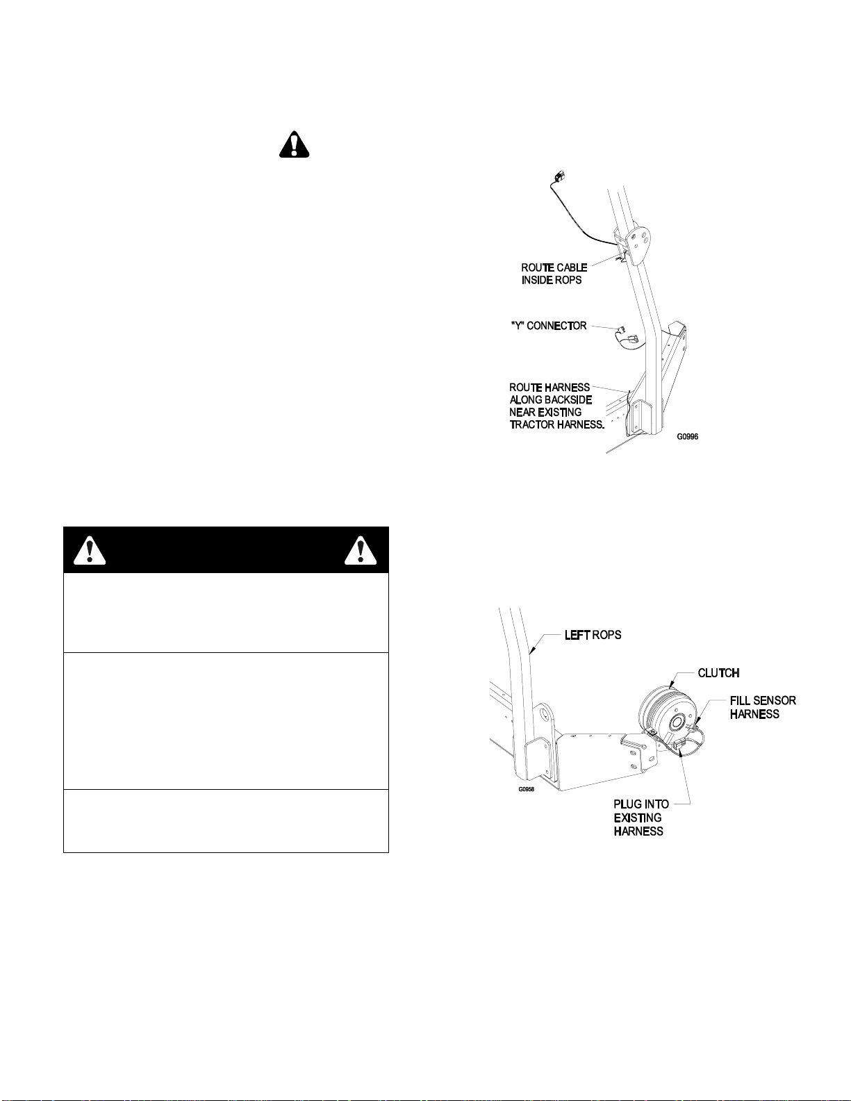
Route the Fill Sensor Wiring
1. Locate the wire harness for the fill sensor.
2. There is a “Y” connector on one end of the
harness. Snake this end down the inside of the
LH ROPS tube. See Figure 2.
FIGURE 2
3. Using the zipties provided, route wiring harness
along existing tractor harness to the rear of the
machine near the clutch.
4. At the back of the machine, unplug the tractor
harness from the clutch.
5. Connect the fill sensor harness between the
clutch and tractor harness as shown in Figure 3.
FIGURE 3
Page 4 of 7
109-6609 Rev. C
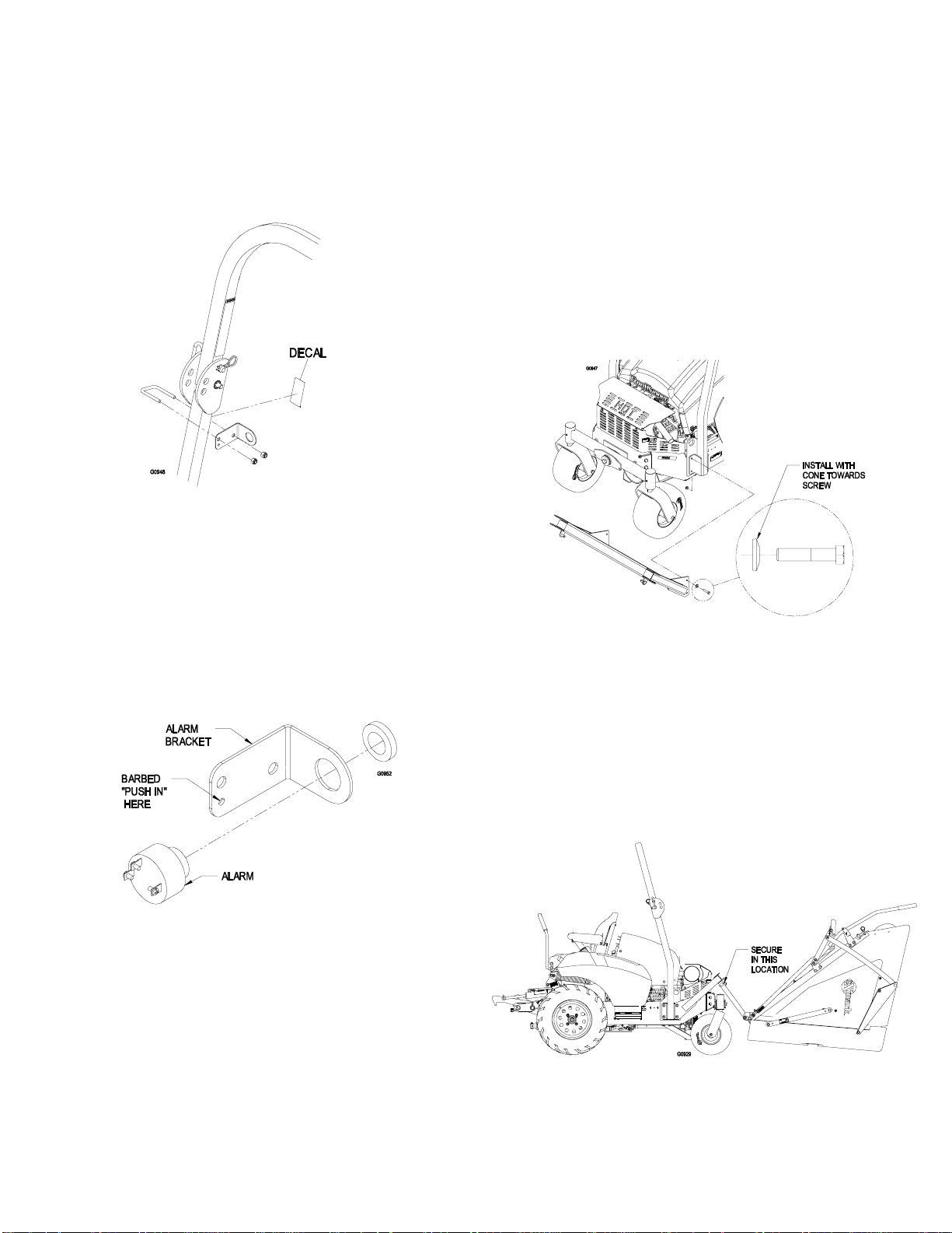
Assemble the Fill Sensor Alarm
Bracket
1. Apply the decal (109-5606) to the front of the LH
ROPS tube as shown in Figure 4. Locate the fill
sensor alarm bracket, u-bolt and hardware.
Assemble to top of LH ROPS tube.
FIGURE 4
Assemble the Fill Sensor Alarm
1. The fill sensor alarm is pre-assembled to the wiring
harness. Install alarm to bracket by unscrewing the
retaining ring, insert alarm through large hole in
bracket, and reinstall retaining ring hand tight. See
Figure 5.
2. Retain wire harness to alarm bracket by installing
the barbed “push in” into extra hole of alarm
bracket. See Figure 5.
FIGURE 5
Install Hopper Assembly
Note: Reference the previous assembly
diagrams for the Item numbers called out in the
installation instructions.
1. Remove the 2 bolts in the rear of the lower
ROPS tubes on each side to allow for
installation of the Ultra Vac.
2. Install the mount weldment (Item 4) loosely to
the rear of the machine using (4) 3/8-16 x 1.5”
screws, 3/8” spring disc washers and 3/8”
whizlock nuts provided. Make sure that the
raised portion of the spring disk washer faces
the head of the screw. (See Figure 6).
FIGURE 6
3. Loosen (but do not remove) the remaining 2
front screws on each side retaining the lower
ROPS tubes to the frame.
4. Apply a light coat of grease to the top surface of
the mount weldment. Install the hopper
assembly (Item 1) by laying the hopper
assembly back on the door, pivot the lower links
forward and slip the ends over the pins on the
mount weldment. Secure the assembly to the
mount using hairpins (Item 9). See Figure 7.
FIGURE 7

Page 5 of 7
109-6609 Rev. C
5. Lift the rear of the hopper assembly, pivoting it
upwards towards the ROPS. Using the pins
provided on the hopper assembly, pin the hopper
assembly to the ROPS plates. See Figure 8.
FIGURE 8
6. Torque all lower roll bar and mount hardware
attached to the machine frame to 30-35 ft-lbs
(41-47 N-m).
7. Plug wire harness into bulkhead connector on
hopper. (See Figure 9.)
FIGURE 9
Installation of Blower Assembly
1. Lower the deck fully. Remove the right hand belt
cover.
2. Remove the blade from the right spindle.
3. Insert special tool 109-2979 into splined end of
spindle shaft.
4. Remove the right sheave nut, spring disk washer,
and drive sheave from the spindle shaft– keep
hardware for re-use.
Use special tool 109-2979 to hold spindle from
rotating. Do not use the blade bolt to prevent
rotation.
5. Apply a light coat of Mobil HTS grease (or food
grade antiseize) to the top portion of the spindle
shaft where the sheave mounts.
6. Install the double sheave onto the right spindle
shaft. Install the spring disk washer and nut.
Make sure that the spring disk washer cone is
installed towards nut (See Figure 10). Torque
the sheave nut to 140-145 ft-lbs.
Use special tool 109-2979 to hold spindle
from rotating. Do not use the blade bolt to
prevent rotation.
FIGURE 10
Reinstall blade and torque 1/2-20x2 blade
bolt to 50-60 ft-lbs (75-81 N-m).
7. Reinstall the deck drive belt in the lower groove
of the double sheave. Install plug (Item 19) into
bore of double sheave.
8. Remove the discharge chute from the deck.
Discard the mounting hardware, but save the
discharge chute for use during side discharge
operation. The chute pivot pin (Item 10) and
hairpin (Item 11) may be stored in the pivot
holes on the discharge chute during bagging
operation.
9. Remove and discard existing hardware in deck
hole shown. Install the longer belt cover
mounting bolt (Item 16) into hole in deck as
shown in Figure 11.
FIGURE 11

Page 6 of 7
109-6609 Rev. C
10. Install the mounting pin weldment (Item 8) to the
blower assembly using the 3/8-16 x .75 bolts (Item
15) and whizlock nuts (Item 24). Maximum deck
clearance will be provided if the bolts are installed
from below the mounting pin. There are (2) different
mounting pin weldments, install as shown. (See
Figure 12).
FIGURE 12
11. Install the belt (Item 7) onto the blower by working it
around the impeller sheave.
12. Mount the blower on the deck by sliding the
mounting pin into the tube at the rear right corner of
the deck. Swing the blower closed. Adjust the
position of the front pin to engage the slot in the
front of the deck. Use the latch to lock the blower in
this position. Adjust the tension on the latch to hold
the blower up to the deck, yet allow for release by
hand.
13. Pull the spring loaded idler back and slip the belt
over the top deck spindle sheave.
14. Install the plastic belt cover (Item 5). The rear of the
cover is slotted and can slip between the knob and
deck reinforcement plate. The knob retaining the
front of the original steel belt cover must be reused
and installed after the new plastic cover has been
positioned.
Assemble the Tube
1. The hopper inlet has ribs to engage the spiral
reinforcement of the flexible tube. Using a marker or
paint pen, mark the flexible tube approximately 4”
from the end. Insert the end of the tube into the
hopper inlet, and rotate clockwise to engage.
Rotate and thread the tube into the hopper inlet
up to the 4” mark. It may be easier to “push” the
tube into the inlet rather than rotating. (See
Figure 13.)
FIGURE 13
1. Orient hose adapter flange on tube with hose
adapter flange on blower housing (it only goes
on one way). Engage shoulder bolts through
keyholes in adapter flange on blower and rotate
to lock. Insert lock pin in small hole in top of
flange to lock in place. See Figure 14.
FIGURE 14
Operation
Pre-Start
1. Read the operator’s manual for the mower and
Ultra Vac to familiarize yourself with all controls
before operating the machine. Make sure that
you understand the controls, their locations,
their functions, and their safety requirements.
2. Ensure the blower, belt cover, flexible tube and
hopper assembly are in good condition, properly
attached, and latched.
Run In
1. Verify that the blower drive operates correctly
prior to delivery to customer.
2. The Ultra Vac blower operates when deck drive
is engaged. Be sure that all persons are clear
of the mower deck and blower before engaging
the cutting blades. Set the throttle to “midway”

Page 7 of 7
109-6609 Rev. C
position. Pull outward on the PTO switch to the
“ROTATE” position.
3. To disengage the deck drive and blower, set the
throttle to “midway” position. Push in on the PTO
switch to the “STOP” position to stop the cutting
blades and blower. The cutting blades will require a
slightly longer amount of time to come to a complete
stop when the blower is installed on the deck.
Fill Sensor
The fill sensor is located at the front of the hopper, and is
wired into the PTO circuit. When grass fills the hopper
enough to block one or both sensors, an alarm will sound.
The fill sensor testing must be made with the PTO
engaged, but the engine does not have to be running.
1. Stop engine, wait for all moving parts to stop, and
remove key. Engage parking brake. Unlatch the door
and pull the door handle engagement pin to raise the
door to the top of the hopper (see Figure 15.)
FIGURE 15
2. Reach into the hopper and place a piece of masking or
duct tape over the LH sensor. It may be helpful to
remove the screen as shown in Figure 15.
3. Close the door.
4. Sit in the seat and turn the key to the RUN position, but
DO NOT START the unit.
5. Pull up on the PTO switch to engage power to the
clutch; you should hear a click from the clutch.
6. There is a split second delay before the fill sensor
alarm will sound.
7. Repeat steps 1-3 to remove the tape from the sensor.
Adjustments
The FrontRunner Ultra Vac was adjusted at the factory
to operate properly. However, there are three basic
adjustments that can be made, should your unit require
them:
1. Fill sensors: Located inside the hopper, they
sound an alarm when the hopper is full. They
can be adjusted for varying grass conditions that
fill the hopper differently (see Figure 16).
FIGURE 16
Moving the LH sensor up works better in wetter
conditions.
Moving the LH sensor down works better in
dryer conditions.
2. Latches: The latches (Figure 17) can be
adjusted. With the door closed, the latch plate
should be set so that the latch cams completely
engage and contact the latch plates bolted to
the door.
FIGURE 17
3. Latch handle link: The latch handle needs to
be able to snap over-center to keep the latch
cams tight against the door latch plates and the
door pulled shut. The length of the latch linkage
is controlled by the two whizlock nuts on either
side of the latch link (Figure 17). The whizlock
nuts should be adjusted so that reasonable
force on the handle is required to over-center
and latch the door. Do not adjust so that the
over-center spring collapses completely when
the door is fully latched.
This manual suits for next models
5
Other Exmark Vacuum Cleaner manuals


