EyeClick BEAM User manual

INSTALLATION GUIDE
TABLE

Thank you for purchasing your new BEAM. Here's what's included:
The BEAM system Power cord Remote controller
for controlling the BEAM projector
The BEAM keyboard
for operating the system menus
WHAT’S IN THE BOX
1 32 4

Before starting the installation and setup, please make sure that:
BEFORE INSTALLING
Full batteries are equipped in both the
keyboard and remote controller.
The keyboard's toggle on the is on and
its green background is visible.
1 32
The yellow saftey ribbon is pulled out
of the batteries compartment.

In order to hang your BEAM from the ceiling, please prepare:
BEFORE INSTALLING
4 TURNBUCKLES
HOOK/EYE
4 CONCRETE EYE BOLT
ANCHORS
4 CHAINS
See chart on slide 6 to
determin required length
4 CARABINER CLIPS
Note
Please prepare a measuring tool, a marker, a drill, a pair of pliers and a leveler for the installation process itself.
An internet connection is required to complete the device setup.

TECHNICAL SPECIFICATIONS
The BEAM device dimentions and
measurments in milimeters:
TOP
BACK
LEFT

RECTANGULAR TABLE SETUP
PROJECTION SURFACE MINIMUM ZOOM MAXIMUM ZOOM
Distance from surface to device Width Height Width Height
140 120 75 142 88
150 126 78 150 94
160 134 83 160 100
170 140 88 168 105
180 148 92 177 110
190 156 97 186 116
200 163 101 194 121
210 170 106 203 126
220 178 111 212 132
225 181 113 216 135
Use this table to determine if the
installation location can accomodate the
desired projection size.
All measurments are in centimeters.
Note
Mounting the device more than 425
centimiters above the projection
surface may produce false interactions
and sensor inaccuracies.

ROUND TABLE SETUP
PROJECTION SURFACE MINIMUM ZOOM MAXIMUM ZOOM
Distance from surface to device Projection Diameter Projection Diameter
140 75 88
150 78 94
160 83 100
170 88 105
180 92 110
190 97 116
200 101 121
210 106 126
220 111 132
225 113 135
Use this table to determine if the
installation location can accomodate the
desired projection size.
All measurments are in centimeters.
Note
Mounting the device more than 425
centimiters above the projection
surface may produce false interactions
and sensor inaccuracies.

INSTALLING BEAM
Unpack the device and place it face
down on a soft surface such as a carpet.
Each end of the turnbuckles should
be screwed to it's middle to allow for
maximum adjustment range.
1 3
Attach each of the carabiner clips to the four ear loops on the top panel.
Next, connect the turnbuckles to the carabiner clips.
2
X X

INSTALLING BEAM
Locate the center of the projection area - the device will be installed directly
above it. Measure a square on the ceiling above the center of the projection area.
The square must be at least 60 centimeters (24 inches) in length and width. Mark
the square's corners.
In order to leave sucient space for the projection area, keep a distance of at least
100 centimeters between the marked square (where you intend to install the
device) and any nearby walls.
4
PROJECTION AREA DISTANCE FROM WALLS

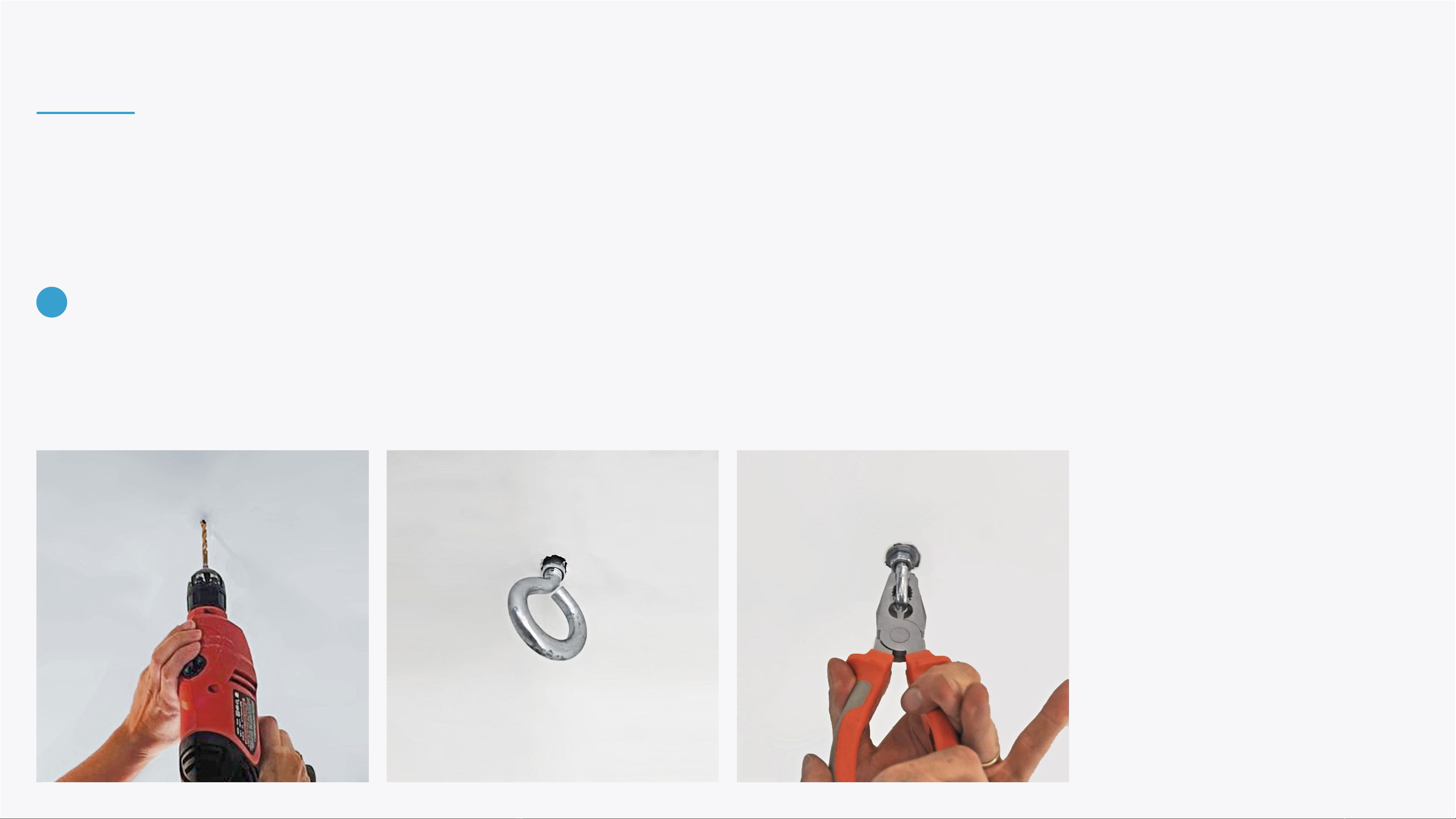
Drill holes at of the square's marked corners. Make sure the drilled holes depth and
diamater match the measurments of your eye bolt anchors. Insert an eye bolt
anchor to each one of the drilled holes.
Fasten the bolts in place.
5
INSTALLING BEAM

Mount the device by attaching one end of each chain to each of the hook bolt
anchors, and the other end to the turnbuckles connected to the device's top panel.
Place the leveler on the device and
adjust the turnbuckles until the device is
completely levelled.
6 7
INSTALLING BEAM

Connect the device to a 15A 110-240V
dedicated, stable power outlet. The
power socket is located on the device's
front panel.
Connect the device to your router using
an Ethernet cable. The internet port is
located on the device's back panel.
It is also possible to connect to a WiFi
network during the device setup.
Turn on the projector using the remote
controller. Allow up to 10 minutes for
the projector's initial activation.
Once the projector is fully activated, use
the projector's zoom and focus wheels
to adjust the image.
8 9 10
INSTALLING BEAM
11

DROP FALSE CEILING INSTALLATION
To install BEAM in a location with a drop (false) ceiling,
anchor the device to the true ceiling or a support beam
as previously explained. Use the drop ceiling's frame to
level the device.
Make sure the device's weight is fully supported by the
chains attached to the true ceiling or a support beam -
the drop ceiling's frame shouldn't carry the device's weight.

Alternatively, you can use a pole for an open ceiling installation. Simply connect
the pole to the device's top panel.
If you're installing the device to a metal
ceiling, use suitable hook bolt anchors
for metal surfaces.
INSTALLING BEAM
TOP PANEL POLE MOUNT

SETTING UP YOUR BEAM
If needed, it's possible to slightly adjust
the projection position after installing
the device.
Release the mirror's Hex / Allen screws
and gently nudge it to tilt the projection
back or forth.
If the projection is skewed, straighten it by clicking
the menu button on your projection remote, then
Settings, and select to adjust the Keystones.
Note that after adjusting the keystones, the projection
must be calibrated (calibration is available in the
Settings section in the control area).
Set up the projection are so it will cover the table you aim to project
on entirly.
If that's not possible due to the ceiling height or zoom limitation, try
to cover as much of the table's surface as possible.
TABLE PLACEMENT IN PROJECTION AREA

SIGN IN & CONFIGURATION
If the projection is illegible during the sign in, conguration or any other point, tap the right
button on the keyboard's trackpad repeatedly until reaching the stanby screen, then type Bto
reset the projection.
Note that after resetting the projection, it must be
adjusted and calibrated (calibration is available in the
Settings section in the control area).

SIGN IN & CONFIGURATION
After nishing the initial projection setup
and turning on your device, the login
screen will be displayed.
CONNECT TO INTERNET
If the device is not connected
through an Ethernet cable, select
the WI-FI button and select and
available network to connect to.
LOGIN
Select the login button to continue.
ENTER CREDENTIALS
Note that these are case-sensitive.
Username: eyeclick
Password: Qwerty!#
The device's serial number is listed on
the sticker on the back of the keyboard.
1
3
2
1 3
2

SIGN IN & CONFIGURATION
Once you've logged in, the device will start
downloading updates. This step may take up to 20
minutes. The device might restart automatically during
this stage.
Once the device has been updated and is ready, the
progress slider will be replaced by a text: "Not in
schedule".
Hold Ctrl+Q to make the control area appear.
Please read the BEAM QuickStart Guide to learn more
about the control area.
4 5 6

SIGN IN & CONFIGURATION
While in the control area, please hold the
Ctrl key while typing iddqd to access the
maintenance section.
SET UP TEAMVIEWER
Tap the button. A dialog will apear.
In it, select Assign. After, tap the
right button on the trackpad to
return back.
SEND TEAMVIEWER ID
Tap this button to share the ID with
our support team.
77
8
8

SIGN IN & CONFIGURATION
Now let's make sure the motion sensor camera is
capturing the projection area correctly.
Tap CAMERA PREVIEW in the maintenance section. The camera live view will be projected. Make sure that
the entire projection area is visible to the camera.
Tilt the camera mirror to move the direction if needed.
You can also reduce the projection scale through the
zoom wheel on the projector.
Note that any change to the projection setup
requires calibrating it through the Settings section.
910
11
Other manuals for BEAM
1
This manual suits for next models
1
Table of contents
Other EyeClick Projector manuals