EYELA CCA-1112A User manual

R00
This instruction manual is designed to use the product efficiently and safely
with keeping its best performance.
Please keep this manual in a place easily accessible to every user.
IMPORTANT Be sure to read “Safety precautions”
before use.
Tokyo Rikakikai Co., Ltd.
取扱説明書
Refrigerated
C i r c u l a t o r
Model CCA-1112A
取扱説明書
Cool Ace Instruction Manual

Safety precautions
Mishandling or inappropriate usage of this product
may cause some trouble. However, if you know the
proper information before
use, you can avoid almost all these troubles.
Therefore, this manual categorizes the level of
Importance and danger as below with alert mark
and signal word.
Please follow the instructions and use the product
safely.
1. Signal word for warning
Though we are trying to look into conceivable risk of using the product, it is very difficult for us to
expect of all of it. It means that all the instructions in this manual do not cover all the types of
risk that may caused by the product.
However, if you follow the instructions, you surely can handle and operate the product safely.
Please use extreme care when handling the product and to prevent all the potential accidents
and mechanical failures.
Alert mark
Signal word Definition
Mishandling the product may cause serious personal injury or
loss of life.
Mishandling the product may injure users or cause property
damage.
Warning
Caution
Mishandling the product will cause serious personal injury or
loss of life.
Danger

※If you have any trouble reading the warning label because it is worn out and etc.,
please replace with new one. Do not hesitate in contacting us if you require new label.
For high priority danger, warning label is attached on the
machine body.
The position of the label is as below.
Please read the instructions carefully whenever using the
machine.
2. Warning display on the product
Caution
Do not touch the
cooling fin with your
bare hands.
It may cut your
fingers
警告
発火の恐れあり
引火性、可燃性溶液
の使用には、十分注
意すること
Warning
Hot surface
Use extreme caution
when using inflammable
or combustible solution.
Mishandling these
solution may cause a fire.
Ventilation cover
Handle

Check the type and quantity of items before setting up.
1. For safety use ・・・・・・ 1
2. Outline of the product
2 - 1 Application ・・・・・・・・・・ 2
2 - 2 Specification ・・・・・・・・・・ 2
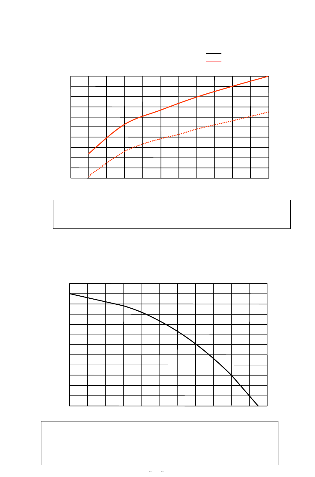
2 - 3 Cooling capability curve(Reference)・4
2 - 4 Circulation capability (Reference)・・・ 4
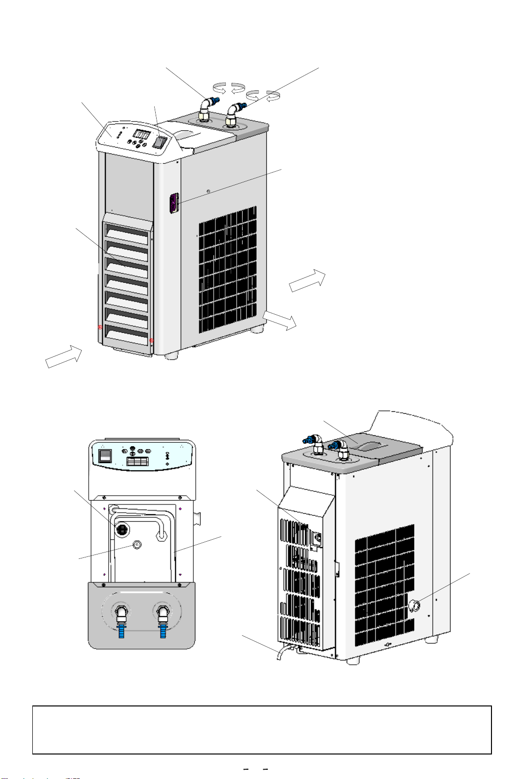
2 - 5 Description ・・・・・・・・・・ 5
3.Names and functions of operating portion
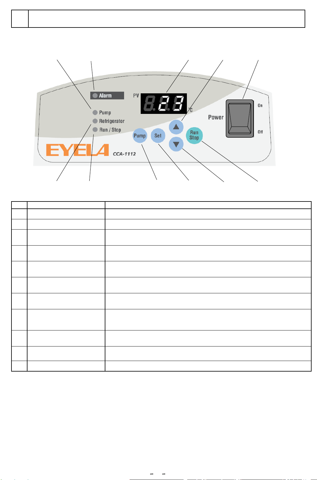
3 - 1 Control panel ・・・・・・ 6
3 - 2 Safety・Alarm functions ・・・・・ 7
4.Installation
4 - 1 Environment・・・・・・・・・・・ 9
4 - 2 Conditions ・・・・・・・・・・・ 9
4 - 3 Utility connection ・・・・・・・ 10
5.Operation
5 - 1 Preparation ・・・・・・・・・・ 11
5 - 2 How to operate the unit・・・・・・ 13
5 - 3 How to use optional accessories ・15
6 Trouble shooting ・・・・・・ 18
Introduction
This manual describes the procedure of
installation, operation, troubleshooting,
maintenance, check-up
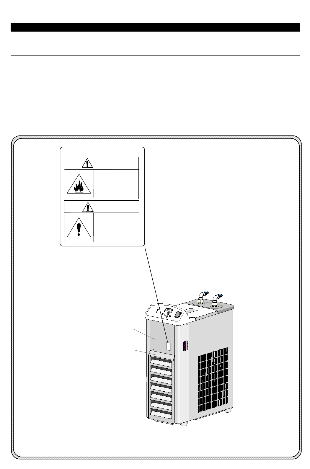
and disposal of Low Temperature Circulator,
CCA-11112A (220V, 60Hz)
Congratulations on your purchase of a
product.
7. Maintenance and checking
7 - 1 Operation test for residual current device ・・20
7 - 2 Caring and cleaning the product ・・20
8. Disposal of the product・・・・・・・・ 22
9.After-sales service ・・・・・・・・ 23
10.Consumable/spare part/optional
accessories ・・・・・・・・ 24
Table of contents
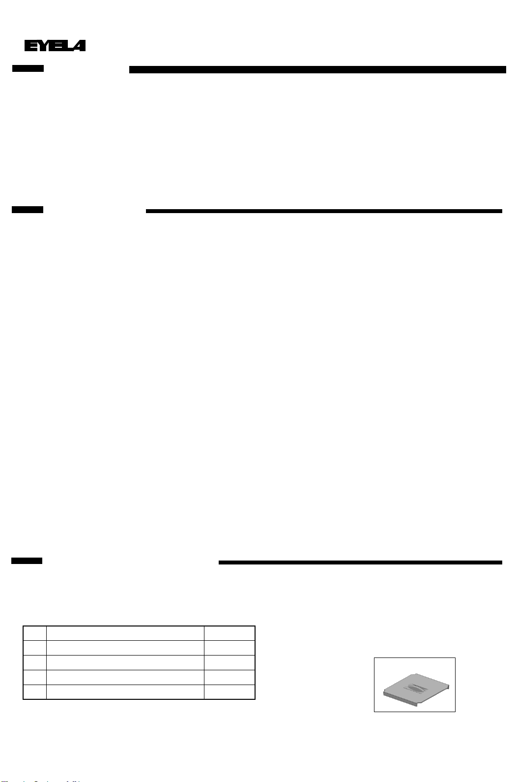
Items contained in your carton
No. Name QTY
1Main unit 1
2Tank cover 1
3Instruction Manual 1
4
Tank cover

1
For safety use
1
Do not touch cooling fin with bare hands while performing maintenance
work. Edgy fin may cut your fingers.
Do not touch cooling fin with bare hands.
Use extreme caution when handling inflammable
or combustible solution.
If you leave inflammable or combustible solution (ethanol and etc.)
at room temperature or higher (lower for some solutions),
it may evaporate and catch fire with some fire sources, and cause
a fire and explode. Ventilate the space well before use.
Caution
Warning
This product is not designed with explosion-proof structure.
Use extreme caution when handling it.
Air filter
Cooling fin

Outline of the product
2
Remodeling or inappropriate use of the
Product may cause electric shock or
malfunction.
Warning
2-1 Application
2-2 Specification
This is a refrigerated circulator
that cools down the liquid in the bath
by refrigeration unit and circulates externally
through circulation pump and cools it off the
heating portion of evaporator(1L), reaction bath
and various devices.
2
※2
-20 ~ + 30°C
±1°C or ±2°C
at 10°C
at 0°C
at -10°C
450W (about 385kcal/h)
350W (about 300kcal/h)
310W (about 266kcal/h)
5.6m ±0.5
10L/min.
5~ 35°C
※1
AC220V 60Hz
28 kg
※3
※4
Do not remodel.
Do not use out of applications.
Product Refrigerated Circulator
Model CCA-1112A
Circulation Closed loop
Circumstance temperature
Temperature range
Control accuracy
Room temperature 20°C
Max. head
Max. flow
Cooling
capacity
Circulation
capacity
Temperature control method
Digital setting by membrane switch,
LED digital display 1°C increment
Ground fault excess current breaker, high
pressure switch for compressor, over-load
relay, protection timer for compressor,
fuse for service ac outlet, self-diagnosis,
thermal protector for circulation pump
Electronic digital setting and digital display
Output 450W, HFC R-404A
3.2L (Liquid capacity :2.7L) SUS 304
Copper (nickel plated)
OD 10 x ID 6.5 mm
Pt sensor
On-OFF control of refrigeration unit
205W x 445D x 545H mm
130W x 230D x 115H mm
Temp. setting, display
Safety feature
Temperature controller
Temperature sensor
Refrigeration unit
Tank capacity
Cooling coil
Circulation nozzle
Overall dimensions
Tank dimensions
Power source
Electrical input
Net weight
Standard Composition Capacity
3.64A 800VA

※1 Heater is not equipped.
・Temperature control not available when the ambient temperature is low , unloaded and high
temperature setting.
※2 Condition
・Room temperature:20℃・Circulation volume:Max. ・No Load ・Supply power and
voltage:AC220V 60Hz
※In using CCA-1112A, ambient temperature is 20℃and unloaded, temperature setting at 30℃
is not available.
・Accuracy of temperature control doffers depending on circulation volume of liquid, type of
refrigerant, heat load and room temperature and other use conditions.
・Displayed temperature may be higher than actual temperature depending on display accuracy of
temperature controller.
Accuracy of temperature control is not the value that is displayed on temperature controller.
※3 Condition
・Room temperature:20℃・Circulation volume:Max.・Supply power and voltage:AC220V 60Hz
・Cooling capability is ±10%of displayed capability.
・Cooling capability differs depending on room temperature, supply power, voltage, type of
refrigerant and stirring condition in the bath.
※4 Condition
・Room temperature:20℃・Supply power, voltage:AC220V 60Hz
・Cooling capability is ±10%of displayed capability.
・Circulation capability differs depending on use conditions (type of the liquid, room temperature
and etc.).
※5 External dimension does not include protrusion.
3

2-3 Cooling capability curve(Reference)
4
Condition ・Supply power, voltage:AC220V,60Hz
・Circulation volume :Max. Room temperature is at 20℃
Room temperature is at 35℃
Caution
Cooling capability differs depending on room temperature, supply power, voltage,
type of refrigerant, condition of stirring in the bath and etc.
50
100
200
300
400
500
550
-20 -10 010 20
Liquid temperature (℃)
30
Cooling
capability(W)
1
2
3
4
5
6
Lifting height (m)
Condition ・Power source:AC220V,60Hz
・Water temperature:20℃
0 1 2 3 4 5 6 7 8 9
Flow volume (L/min)
10 11
0
2-4 Circulation capability(Reference)
Caution
※Circulation capability differs depending on diameter of nozzle,
piping, type of solvent and other conditions.
※If you conduct sealed operation for circulation pump, it may
cause malfunction on the pump.

2-5 Description
5
Control panel
Residual current device
External circulation
discharge nozzle (IN)
External circulation
discharge nozzle(OUT)
Ventilation
※The unit is coated with ABS (control panel), polyphenylene ether (bath cover), polyacetal (nozzle and drain plug)
and nitrile rubber (tray). (These are nonferrous materials). Compared to metals, these plastics and rubbers can
be easily discolored, deformed and damaged by heat, light (example: direct sun), solution (example: circulation
liquid, cleanser) and forces (impact). So use caution when handling the unit.
Ventilation
Ventilation
cover
Power switch
Air intake
Tank cover
Drain plug
Power cord
Temperature
sensor
Strainer
OUT
IN
Cooling coil
Communication
connector

6
Functions and names of operating portion
3
3-1 Control panel
No. Name Functions
①Power switch Turns on and off the power.
②Indicator Displays measured, setting temperature, alarm and characters.
③Up key Each time you press the key, the value increases by 1.
Pressing and holding the key can increase the value continuously.
④Down key Each time you press the key, the value decreases by 1.
Pressing and holding the key can decrease the value continuously
⑤Run/Stop key Starts and stops control.
⑥Set/Clear key Switches measured and setting temperature and determines the setting
temperature. Clears alarm display when the alarm is activated.
⑦Pump key Runs and stops pump.
⑧Alarm LED Lights up when refrigeration unit or sensor is in abnormal condition, or
upper or lower temperature limit alarm is activated.
⑨Pump LED Lights up when pump is controlled.
⑩Refrigeration unit LED Lights up when refrigeration unit is turned on.
⑪Run/Stop LED Lights up when the control is on.
①
② ③
⑥ ④ ⑤
⑨ ⑧
⑦⑩ ⑪
A

Safety features
This product is equipped with the following safety
features and alarm features. If you face any trouble, please refer to
“Troubleshooting" on page 18 and follow the
instruction.
3-2 Safety・alarm features
Alarm functions
7
Safety device Operations Reasons why the device works.
Residual current
device Power is turned off. ・Electric leakage hazard occurs, or excess
current flows.
Over load relay for
refrigeration unit Refrigeration unit runs over load
(over heat) operation, which makes
alarm lamp light up and 「A14」will
be displayed on indicator to stop
refrigeration unit and pump.
Refrigeration unit runs over load (over heat)
operation (start-up).
・Power and voltage variation exceeds the rated
value(±10%).
Impedance
protector for
circulation pump
Controls electric flow of pump while
circulation pump runs over heat
operation, and also controls
temperature rise to prevent the
burning of pump.
Constraint operation because of over load of
circulation pump
・Viscosity of circulation liquid is high.
・Foreign substances are sucked in.
・Ambient temperature exceeds 35℃.
・Pipe resistance is too strong(Valve is too
tightened and etc.)
Self-diagnosis
function for control
basal plate
(Watch dog)
Control basal plate is in abnormal
condition, which stops control.
・Ambient temperature exceeds 35℃.
・Influence of noise and etc.
Alarm name Alarm display and operations Reasons why alarm is activated.
Temperature
sensor alarm ・All the controls(for refrigeration unit and circulation
pump output) gets stopped.
・[Alarm]LED lights up.
・Alarm description will be displayed on indicator.
Operations
・Temperature sensor is
disconnected.
Releasing alarm
・Alarm can be released when
turning the power switch on
again.
Upper
temperature limit
alarm
・[Alarm]LED lights up.
・Indicator displays “Measured temperature” and
“Setting temperature” alternately.
Operation conditions
・Alarm is activated when the bath
temperature is higher than
「Setting temperature+setting
temperature for upper
temperature limit alarm」.
Releasing alarm
・Alarm can be released by
「Set」key.
Refrigerator
Pump
Run/Stop
Alarm PV
℃
Refrigerator
Pump
Run/Stop
Alarm PV
℃

8
Alarm name Alarm display and operations Reasons why alarm is activated.
Lower temperature
limit alarm
・All the controls (refrigeration unit・circulation
pump output)get stopped.
・[Alarm]LED lights up.
・Indicator displays the alarm description. Operation conditions
・Alarm is activated when the bath
temperature is lower than
「Setting temperature-setting
temperature for lower
temperature limit alarm」.
Releasing alarm
・Alarm can be released by
「Set」key.
Refrigeration unit
alarm
・All the controls (refrigeration unit・circulation
pump output)get stopped.
・[Alarm]LED lights up.
・Indicator displays the alarm description. Operation conditions
・Refrigeration unit protector (over
load relay)works.
Releasing alarm
・Alarm can be released by
「Set」key.
Refrigerator
Pump
Run/Stop
Alarm PV
℃
Refrigerator
Pump
Run/Stop
Alarm PV
℃

9
Installation
4
4-1 Installation condition
CAUTION
Select appropriate installation
site that can be ventilated well.
Since air-cooled type refrigeration unit is equipped with
this product, heat is exhausted from the unit.
Select the installation site that can be ventilated well so
that the ambient temperature won’t rise because of
exhausted heat. Using the product in high ambient
temperature may worsen the operation efficiency or
cooling capability. Also, refrigeration unit will be
hot and operate under high pressure, which may cause
malfunction.
Select the installation site that meets the following
conditions.
◎No inflammable solid or liquid or gas around the
unit.
◎Ambient temperature must be from 5 to 35℃.
◎No dew condensation
◎Lesser humidity and no dripping on the unit.
◎Lesser dust
◎No direct sun light
◎Well-ventilated.
◎Level and stable
(Check the weight of the product during operation.)
4-2 Installation conditions
Caution
Keep enough space around the unit.
To keep the best performance of the product, leave
the space between product and wall, ceiling plane.
The distance between the product and wall, ceiling
plane must be longer than the one mentioned in the
right picture.
Caution
This product is a heavyweight product.
Use caution when carrying the product
CCA-1112A:Approx. 28kg
※Do not block
the ventilation
port.
30cm
Caution
Do not put on anything on this unit.
Caution
Do not tilt the unit more than 15°.
This unit contains a refrigeration unit.
Do not tilt the unit more than 15°for moving.

10
4-3 Utility connection
Warning
Check the voltage, phase and
capacity of power source before
connecting.
Inappropriate connection may cause a fire or
electric shock hazard.
1. Check the voltage, phase and capacity of
the power source. Required power source
is as shown in right table.
2. Check the type of outlet at the installation site.
(Do not connect the mains connector yet.)
If the outlet has earth terminal, mains connector
can be connected.
If the earth terminal is not available, connect
grounding adapter to power plug.
Connect earth wire of grounding adapter to earth
terminal.
※Grounding adapter is not supplied with the
product.
Warning
Ground the unit properly.
Without grounding the unit, the product may
cause electric shock hazard.
Warning
Do not use branching socket.
Excess current may burn cable or cause a fire.
Model Required power source
Voltage Capacity
CCA-1112A AC-220V
Single phase
15A

Operation
5
5-1 Preparation
Warning
Use extreme caution when using
combustible or inflammable solution.
If you leave combustible or inflammable solution
(methanol and etc.) out at room temperature or
higher (lower for some solutions) , it may evaporate
and catch fire with some ignition source, and cause
explosion. Ventilate the space well while using these
solutions.
1 Connecting pipes and hose
1)Loosen nut for fixing nozzle and make sure
that o ring is fixed at the slot for fixing o ring.
2)With holding nozzle with your hands, tighten
the nut so that the water won’t be leaked.
3)Connect hose (Diameter: 9mm) to external
circulation nozzle (IN & OUT) and the device
to be cooled down. Attach hose band to fix the
hose (hose and hose band are not supplied
with the product).
※Do not jack up the nozzle too much.
※Do not change the direction of nozzle during
operation to prevent damage or leak.
※Material of the hose must have appropriate
pressure and fever-resistance and it must not
be affected by any solutions. Also, make sure
that hose is not bended or crashed when using
the unit.
Caution
Use circulation liquid that does
not affect the material of
circulation route inside the unit.
Materials used for the circulation route are
copper, stainless, brass, fluorine resin, polyacetal,
silicon rubber, polyphenylene ether, ethylene
propylene rubber. Use circulation liquid that does
not affect these materials. Or some parts in the
circulation route may be damaged. Also, do not
use extra-pure water or ion exchange water.
These water may solve carbon dioxide in the air
and generate acid solution, which may corrode
the metal of circulation route.
Caution
Use the hose at appropriate
length.
Use the hose at appropriate length.
When the piping resistance is strong,
cooling capability or temperature distribution
in the circulation bath will be worsen
because of small quantity of circulation water.
Caution
Do not conduct closed operation
or idling of circulation pump.
These operation may cause malfunction.
11
Elbow
Circulation house)
(WATER IN)
Circulation hose
(WATER OUT)
Hose
Hose
Force the brim into it.
Brim
Pull the hose nozzle
When removing one touch hose nozzle, a hose nozzle
is pulled out while forcing the brim of a revolving elbow
as the arrow shows.
The end of a hose cuts perpendicularly and check
there is no uneven section or there is no foreign
substance around a hose.
The uneven section of a hose may be a cause of
water leakage.
Hose
Right angle
No uneven section

12
Cooling water level
2. Filling cooling water
1)Make sure that drain plug is connected to
drain hose.
2)Fill the water in the bath up to the position
where cooling coil is fully filled (CCA-1112A:
Approx. 2.7L).
※Use anti-freeze liquid, if you use the unit at +7℃
or lower. However, if you use ethylene glycol or
Nybrine, the viscosity will be higher in low
temperature, which makes temperature
distribution in the bath worse.
In such a case, mix the moderate amount of
water ( Make sure the freezing temperature when
the liquid is concentrated.)
※Make sure that there’s no foreign substance
in circulation liquid, which will cause malfunction.
3) Set the bath cover on the main unit.
3.Connecting power plug
Make sure that residual current device and power
switch are turned off before connecting power
plug to outlet.
Caution
Do not get control panel wet.
When filling water into the bath, do not get control
panel wet. It will cause malfunction in controlling
portion or electric shock hazard because of
electric leakage.
※The unit is coated with ABS (control panel),
polyphenylene ether (bath cover), polyacetal
(nozzle and drain plug) and nitrile rubber (tray).
(These are nonferrous materials). Compared to
metals, these plastics and rubbers can be
easily discolored, deformed and damaged by
heat, light (example: direct sun), solution
(example: circulation liquid, cleanser) and
forces (impact). So use caution when handling
the unit.
Do not use pure water
Use tap water or softened tap water.
Do not use pure water or ion exchange water.
These types of water solve carbon dioxide in
the air into acid solution, which could corrode
the metal of circulation route.
Also, pin hole of cooling coil or circulation
pump may be impaired because of the use of
these water.
Hose for one touch
connector
Revolving
elbow Recommended hose: Nitta Co., Ltd.
- PL Tube PL-4-10
- PN Tube PN-4-10
■In case of direct insertion of hose to revolving elbow
Insert the hose to the revolving elbow directly
(Insert the hose to the revolving elbow firmly
until it touches the inside of elbow.)
Cooling coil
Water level
About 2cm

13
Turn on residual current device, excess current
breaker and power switch.
In about 1 seconds after displaying initial display,
measured temperature of cool water circulating
bath will be displayed(measuring mode)
※On「 」, the specific value or
alphabet will be displayed.
1.Setting temperature
Setting temperature can be changed regardless
of the status of the unit.
1) Setting temperature(setting mode)
Press[Set]key. Indicator changes to
display setting temperature (blinking) and you
can set the temperature.
※Setting temperature is the value you used
previous time. Factory default is 「20℃」.
2) Changing setting temperature
Press[▲]or[▼]key to input setting
temperature
※Each time you press[▲]or[▼]key, the
temperature changes by 1℃and holding down
the key for longer can change the value
continuously.
3) Determining setting temperature
Press[Set]key. Displayed setting
temperature (blinking) is determined and
indicator changes to display measured
temperature (measuring mode) .
※If no key operation is done for longer than 5
seconds, changed preset temperature can not be
determined and indicator changes to display
measured temperature (measuring mode). In such
a case, please reset from 1).
※Status of LED
「」、「 」Turns off a light
「」、「 」Lights up
「」、「 」Blinks
5-2 How to operate the unit Initial screen
After approx. 1 sec.
2) Changing setting temperature
Press
Press
Refrigerator
Pump
Run/Stop
Alarm PV
℃
Pump Set
▲
▼
Run
Stop
Refrigerator
Pump
Run/Stop
Alarm PV
℃
Pump Set
▲
▼
Run
Stop
Refrigerator
Pump
Run/Stop
Alarm PV
℃
Pump Set
▲
▼
Run
Stop
Refrigerator
Pump
Run/Stop
Alarm PV
℃
Pump Set
▲
▼
Run
Stop
Refrigerator
Pump
Run/Stop
Alarm PV
℃
Pump Set
▲
▼
Run
Stop
Measure temperature display
1) temperature setting
3) Detemining setting temperature

14
2. Starting operation
1) Running circulation pump
Press[Pump]key. Circulation pump starts
working and circulating externally.
・「Pump LED(Pump)」lights up.
※Make sure that connecting part of hose and nozzle
have no leak.
※If the liquid does not circulate, the air may be
sucked in the pump. So release the air.
※Pressing [Run/Stop] key does not work on circulation
pump.
2) Filling cool water
Since filling the water in circulation system makes the
water level lower, refill the cool water.
※Refill the cool water up to the level mentioned in the
section 「3. Filling cool water」on page 20.
※Cooling capability will be worsened when cooling coil is
exposed.
※As protective timer for refrigeration unit is equipped,
refrigeration unit won’t start up until the timer stops
after turning the power switch on or the refrigeration
units stops working temporarily.
CCA-1112A:Approx. 70seconds
3. Stopping operation
1) Stopping temperature control
Press[Run/Stop]key to stop temperature control.
・「Temperature LED(℃)」starts lighting up.
・「Refrigerator LED(Refrigerator)」turns off a light.
2) Stopping circulation pump
Press[Pump]key to stop circulation pump.
・「Pump LED(Pump)」turns off a light.
※To stop operation, stop the operation before turning the
power switch off. Turning the switch off without
stopping operation will activate power failure alarm
next time.
※If you do not use the unit for a long time, turn off the
power switch, residual current device, excess current
beaker and disconnect power plug from outlet.
Also, drain the water from bath and pipe (check the
bath and pipe regularly in winter time so that water
won’ be frozen).
1) Running circulation pump
Press
3) Starting temperature control
1) Stopping temperature control
Press
Press
Drain plugDrainage hose
※Releasing air
Remove drain plug and make sure that coolant is
drained from drainage plug and put the plug on.
Then, turn circulation pump on and off repeatedly
for twice or 3 times to release air from the pump
Refrigerator
Pump
Run/Stop
Alarm PV
℃
Pump Set
▲
▼
Run
Stop
Refrigerator
Pump
Run/Stop
Alarm PV
℃
Pump Set
▲
▼
Run
Stop
Refrigerator
Pump
Run/Stop
Alarm PV
℃
Pump Set
▲
▼
Run
Stop
Press
Refrigerator
Pump
Run/Stop
Alarm PV
℃
Pump Set
▲
▼
Run
Stop
2) Stopping circulation pump

15
5-3 How to use optional accessories
5-3-1. How to use stop valve Caution
Use the hose at appropriate
length.
Use the hose at appropriate length.
When the piping resistance is strong,
cooling capability or temperature distribution
in the circulation bath will be worsen
because of small volume of circulation water.
5-3-2. Stainless steel tank lid.
When circulating volatile liquid such as methanol
as circulation liquid, it should be used. The tank
lid attached as standard accessory is a plastic and
the condition becomes bad for a solvent-resistance
and the weather resistance compared with metal
tank lid.
* The material is SUS304.
If the flow volume is not enough, use the
bigger diameter nozzle (Optional accessory)
to reduce the load in circulation pipes.
Please use the insulated hose set (Optional
accessory) in order to avoid the condensation
of water on the surface of pipes.
* Use the hose at appropriate length and
diameter.
* The material of hose is Polychloroprene.
■Flow Control Valve
Flow control valve 247190
Cat. No. 3/8×3/8
■Metal Nozzle set
Nozzle OD (material) 242420
Cat. No.
Model AL-1 AL-2
13.5(brass)10.5(brass)
AL-6
10.5(SUS) AL-8
13.5(SUS)
243950 243970 243980
■Insulated hose set
Length
Cat.No.
Tube Diameter φ9
1m2m5m
112690 112700 174420
φ12
1m2m5m
113280 143330 174440
(1) Remove a revolving nozzle of IN OUT using
a wrench of opposite side 22mm.
(2) Apply the sealing tape 4~5 times around the threaded
part and force 90°elbow to it.(In and Out)
(3) Force the flow control valve and metal nozzle to outlet
nozzle and force the metal nozzle to inlet nozzle.
Apply the sealing tape 4~5 times around the threaded parts.
Revolving nozzle
Screw
Flow control valve
Elbow (Metal)
Metal nozzle
Stainless steel lid 188060
Cat. No. For CCA-1112A
The insulated hose is a consumable part.
The degradation and the aging of a hose are
different depending on conditions for use, so
please exchange it by check.

16
5-3-5. Carriage
By setting carriage, CCA-1112A can be moved
and installed smoothly on the floor.
1. Position of the carriage
1) Lower the stop lever (for 4 wheels) to lock the
caster so that carriage won’t move.
2) Set the 4 rubber supporters on the carriage.
※Since the weight of the main unit is about
29kg, handle it with two persons.
※Since there’s no space between carriage and
main unit, use caution not to jam your fingers.
2. Carrying and installing the unit
1) Raise the 4 stop levers to unlock and move it
to the installation site.
※Moving the unit on bumpy place will damage
the casters. In such a case, carry the unit.
2)At installation site, lower the stop levers of
casters to lock.
3)Insert supplied 4 caster holders into the caster
to fix.
Caster holder
To unlock
To lock
Stop lever
Caster
Set the rubber supporters (4 points) of the main
unit on the carriage as shown above.
Front
Be careful not to jam
your finger.
Setting carriage
Locking and unlocking the caster
Carriage
Carriage
260460
Cat.No.
For CCA-1112A
■Carriage
Table of contents