Fagor VTP Series User manual

MANUAL DE INSTRUCCIONES
VITRINAS REFRIGERADAS
************
USER GUIDE
REFRIGERATED DISPLAY CASE
Cod: 12067992 (May_15)

1
INSTALACIÓN, USO Y MANTENIMIENTO
ÍNDICE DE CONTENIDOS
1INSTALACIÓN................................................................................................................................1
1.0EMPLAZAMIENTO ..................................................................................................................1
1.1LIMPIEZA ................................................................................................................................2
1.2CONEXIONADO......................................................................................................................2
1.3PLACA MATRÍCULA................................................................................................................3
1.4PUESTA EN MARCHA............................................................................................................5
2USO.................................................................................................................................................6
2.0INSTRUCCIONES DE USO ...................................................................................................6
2.1PRECAUCIONES.....................................................................................................................6
3MANTENIMIENTO..........................................................................................................................6
3.0LIMPIEZA A REALIZAR POR EL USUARIO........................................................................6
3.1CHEQUEO DE LA MÁQUINA.................................................................................................6
3.2MANTENIMIENTO ESPECIAL...............................................................................................7
Antes de poner en marcha la vitrina, queremos agradecerle su confianza en nosotros por adquirir
esta vitrina refrigerada, le recomendamos lea y siga los pasos que en las instrucciones vienen
detalladas.
El presente manual está diseñado para ofrecer la información necesaria para la instalación, puesta
en marcha y mantenimiento de las vitrinas refrigeradas.
La instalación y el mantenimiento especial han de ser realizado por personal técnico cualificado.
PRUEBAS DE FUNCIONAMIENTO
La vitrina que ha adquirido viene preparada para su correcto funcionamiento, el resultado está
certificado por un riguroso test de control de calidad.
Nota: Las fotografías que aparecen en el manual están a modo de ejemplo, puede que no
correspondan con su modelo.
1 INSTALACIÓN
1.0 EMPLAZAMIENTO
La vitrina no se debe de volcar. Retirar el embalaje excepto el palet de apoyo. Para trasladarlo al
lugar de instalación se puede ayudar de una carretilla o traspaleta, levantando la vitrina refrigerada
vigilando que ésta no esté desequilibrada.
La zona donde se ubique la vitrina debe estar despejada y limpia, evitando que el ventilador del
equipo frigorífico absorba materiales que luego son depositados en el aleteado del condensador,
reduciendo la eficiencia del sistema.
Retirar el palet, cuidando de no provocar golpes en el mueble. Ahora se puede nivelar la vitrina,
roscando o desenroscando las patas.

2
1.1 LIMPIEZA
Ya tenemos nuestra vitrina colocada correctamente, ahora debemos limpiarla:
La primera limpieza se debe realizar con agua y detergente neutro. Una vez limpia y seca, introducir
los accesorios en los lugares adecuados, según preferencias.
La limpieza de la parte exterior del mueble, recomendamos a diario, se debe efectuar con un trapo
húmedo. No se debe utilizar nunca sustancias abrasivas o con contenido en cloro.
Aclarar con agua limpia, evitando los chorros de agua directos.
1.2 CONEXIONADO
GENERAL
Antes de conectar la vitrina a la toma de corriente, comprobar que la tensión y la frecuencia de la
red coinciden con las indicadas en la placa de características del aparato.
Es imprescindible que la instalación eléctrica donde se vaya a conectar la vitrina disponga
de TOMA DE TIERRA, así como de la debida protección de magnetotérmico y diferencial
(le aconsejamos de 30mA.)
Comprobar que la sección de la toma de alimentación sea la adecuada para el consumo que va a
soportar.
La toma de corriente ha de ser tipo Schuko ya que la manguera que incorpora su vitrina es de ese
tipo (también llamada tipo F o también llamada CEE 7/4”), con bornes de 4,8mm. y toma de tierra.
Está prohibido alargar dicha manguera de entrada corriente por su seguridad.
No introducir elemento alguno por las rejillas de protección de ventiladores o zona del equipo
frigorífico.
El lugar donde se vaya a colocar el mueble, debe estar perfectamente nivelado.
En la puesta en marcha asegurarse de que no hay ninguna fuente de calor cercana.
Para el perfecto funcionamiento de los elementos que componen el sistema frigorífico, es
importantísimo que la toma de aire del condensador no esté taponada.
No instalar la vitrina a la intemperie.
Adjuntamos tabla de consumos de las vitrinas para que pueda ajustar la protección
VITRINAS TENSION
ALIMENTACION INTENSIDAD
(A) CONSUMO
(W) FUSIBLE
(GL o AM) DISPOSITIVO
DIFERENCIAL
VTP-139 230V 50 Hz 1.5 345 2 30mA
VTP-175 230V 50 Hz 1.6 368 2 30mA
VTP-139-R 230V 50 Hz 1.5 345 2 30mA
VTP-175-R 230V 50 Hz 1.6 368 2 30mA
VTP-139-S 230V 50Hz 1.5 345 2 30mA
VTP-175-S 230V 50Hz 1.6 368 2 30mA
A: ROSCA DE REGULACION
Girar a la derecha para bajar el mueble
Girar a la izquierda para subir el mueble

3
Existen versiones a 220v 60Hz Y 115v 60Hz, las intensidades en placa matrícula.
Además, las vitrinas, bajo pedido, se entregan con mangueras entrada corriente tipo
H (Inglaterra) y tipo B (América)
1.3 PLACA MATRÍCULA
Explicación de la placa matrícula que acompaña su mueble
Nota: Esta placa es a modo de ejemplo.
MEDIDAS GENERALES DEL EXTERIOR DE TODAS LAS VITRINAS EN mm.
MODELO DIMENSIONES
LARGO PROFUNDO ALTO
VTP-139 1386 407 252
VTP-175 1737 407 252
VTP-139-R 1386 407 252
VTP-175-R 1737 407 252
VTP-139-S 1368 407 252
VTP-175-S 1737 407 252
VITRINAS TENSION
ALIMENTACION INTENSIDAD
(A) CONSUMO
(W) FUSIBLE
(GL o AM) DISPOSITIVO
DIFERENCIAL
MI – 135 230V 50 Hz 1 178 2 30mA
MI – 150 230V 50 Hz 1 178 2 30mA
MI – 180 230V 50 Hz 1,1 213 2 30mA
MI – 202 230V 50 Hz 1,1 213 2 30mA
MI – 225 230V 50 Hz 1,1 213 2 30mA
MI – 255 230V 50 Hz 1,1 213 2 30mA
VITRINAS TENSION
ALIMENTACION INTENSIDAD
(A) CONSUMO
(W) FUSIBLE
(GL o AM) DISPOSITIVO
DIFERENCIAL
VC-14-I 230V 50 Hz 2.7 616 4 30mA
VC-14-M 230V 50 Hz 2.7 616 4 30mA
VC-20-I 230V 50 Hz 3.0 704 4 30mA
VC-20-M 230V 50 Hz 3.0 704 4 30mA
VM-100-I 230V 50 Hz 1.7 396 2 30mA
VM-100-M 230V 50 Hz 1.7 396 2 30mA
VM-135-I 230V 50 Hz 1.7 396 2 30mA
VM-135-M 230V 50 Hz 1.7 396 2 30mA
NÚMERO DESCRIPCIÓN
1 EMPRESA CONSTRUCTORA
2 MODELO
3 N.º SERIE
4 WATIOS DE POTENCIA FRIGORÍFICA
5 TENSIÓN DE TRABAJO
6 FRECUENCIA
7 INTENSIDAD DE CORRIENTE
8 TIPO DE GAS REFRIGERANTE
9 GRAMOS DE GAS REFRIGERENTE
10 CLASE CLIMÁTICA (N=4)
11 NORMATIVA

4
MODELO DIMENSIONES
LARGO PROFUNDO ALTO
MI – 135 1340 336 236
MI – 150 1496 336 236
MI – 180 1790 336 236
MI – 202 2019 336 236
MI – 225 2240 336 236
MI – 255 2546 336 236
MI – 135 cúpula 1340 336 436
MI – 150 cúpula 1496 336 436
MI – 180 cúpula 1790 336 436
MI – 202 cúpula 2019 336 436
MI – 225 cúpula 2240 336 436
MI – 255 cúpula 2546 336 436
MODELO DIMENSIONES
LARGO PROFUNDO ALTO
VC-14-I 1380 800 1075
VC-14-M 1380 800 1075
VC-20-I 1980 800 1075
VC-20-M 1980 800 1075
VM-100-I 983 570 1120
VM-100-M 983 570 1120
VM-135-I 1333 570 1120
VM-135-M 1333 570 1120
MEDIDAS COLOCACION DESAGÜE EMERGENCIA

5
1.4 PUESTA EN MARCHA
Una vez limpio el interior de la vitrina, conectar a la red eléctrica y poner el interruptor en
On o en I,el interruptor ha de estar iluminado.
A los tres minutos después del encender el interruptor, el led compresor en marcha ha de
iluminarse permanentemente,
La temperatura que aparece en el visor de temperatura al principio será la temperatura
ambiente. Conforme funcione la máquina, si las puertas están cerradas, irá bajando hasta el
valor de régimen.
Es necesario que la vitrina funcione hasta alcanzar la temperatura de trabajo, antes de
proceder a la carga del género.
Cuadro de mando con interruptor y termostato

6
2 USO
La vitrina adquirida está concebida para la exposición temporal de alimentos. Le aconsejamos no
introducir alimentos o recipientes calientes, así como productos químicos, corrosivos o
medicamentos, y evitar el uso inadecuado del mueble. Para un funcionamiento seguro y
eficiente, asegúrese de seguir las siguientes instrucciones:
2.0 INSTRUCCIONES DE USO
1) No deje alimentos en la vitrina después de las horas de servicio ya que pueden secarse o
echarse a perder. Es aconsejable la desconexión de la vitrina y limpieza diaria después
de su servicio.Los alimentos que no deben resecarse durante su uso, deben ser cubiertos
o envueltos en una película de plástico.
2) Exponer solo alimentos previamente refrigerados. Se necesita más tiempo para que estos
se enfríen en la vitrina que en un refrigerador.
3) Evitar en la medida de lo posible la apertura frecuente de puertas, y sobre todo, no
dejarlas abiertas. La temperatura interior puede aumentar, lo que ayuda al deterioro de
los alimentos.
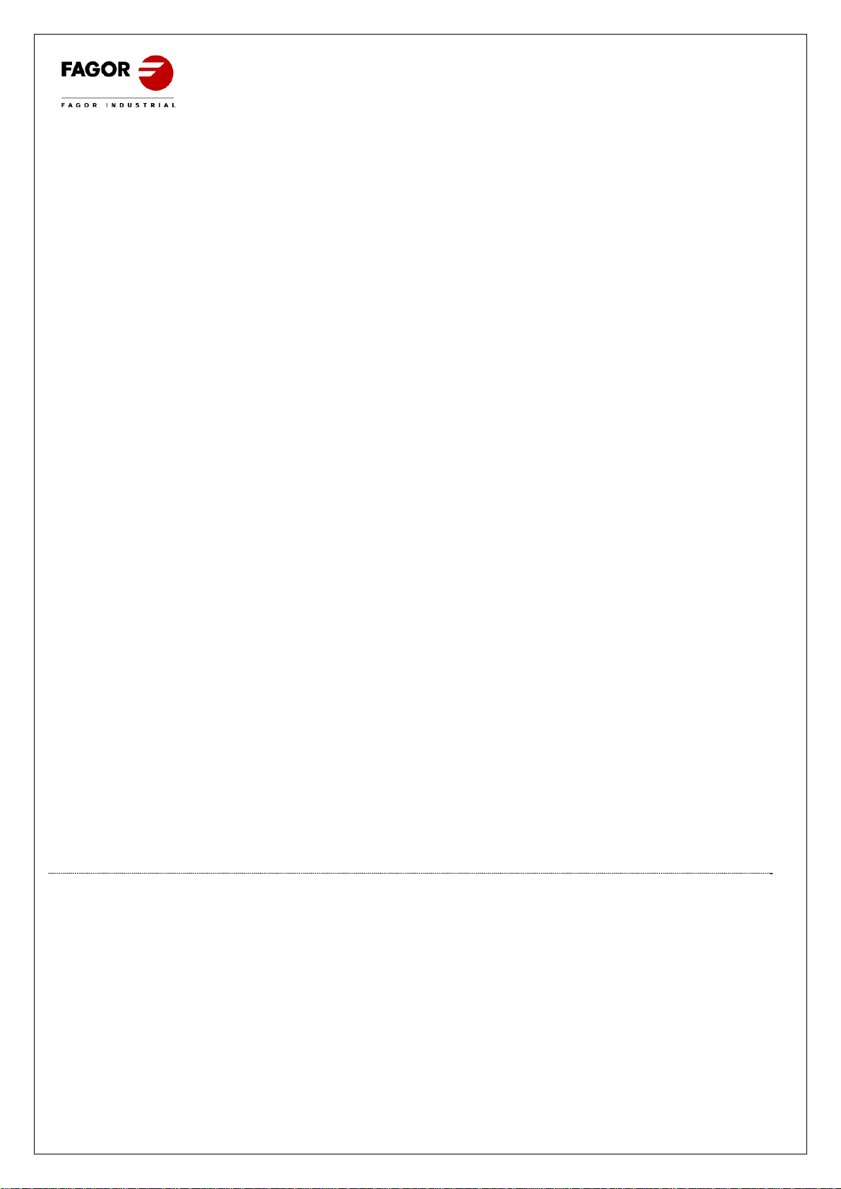
4) La temperatura ambiente no debe superar los 32ºC (25ºC para vitrinas Sushi (S)). El
rendimiento de enfriamiento puede reducirse, ayudando al deterioro de los alimentos.
2.1 PRECAUCIONES
1) Toda la superficie exterior de la vitrina esta realizada en cristal, por lo cual es necesario
tener precaución a la hora de colocar elementos sobre ella, evitando en la medida de lo
posible los golpes (peligro de rotura del cristal).
2) En caso de avería, no está permitido acercarse a la vitrina descalzo, con el suelo mojado
o con las manos húmedas.
3 MANTENIMIENTO
En este punto trataremos sobre la limpieza que usted puede realizar así como un breve chequeo
de la máquina antes de avisar al servicio técnico. Esperamos que le sea útil.
3.0 LIMPIEZA A REALIZAR POR EL USUARIO
Antes de realizar cualquier operación de limpieza, hay que proceder a desconectar el aparato de
la toma de corriente, y colocar el interruptor general en posición OFF o 0.
Las vitrinas van provistas de desagüe para facilitar su limpieza, así como la eventual salida de
líquidos procedentes de los alimentos. Durante la operación de limpieza es imprescindible quitar
el tapón del desagüe y limpiar éste, para evitar la obstrucción por arrastre de elementos sólidos.
Se pretende que los líquidos que pueda haber no se estanquen.
3.1 CHEQUEO DE LA MÁQUINA
En caso de que tenga que solicitar la intervención del técnico puede realizar un chequeo de la
vitrina antes de llamarlo. En algunos casos los fallos de funcionamiento que pueden surgir, son
por causas simples que el propio usuario puede solucionar.
A modo de ejemplos podemos citar algunos:
a) La vitrina no funciona
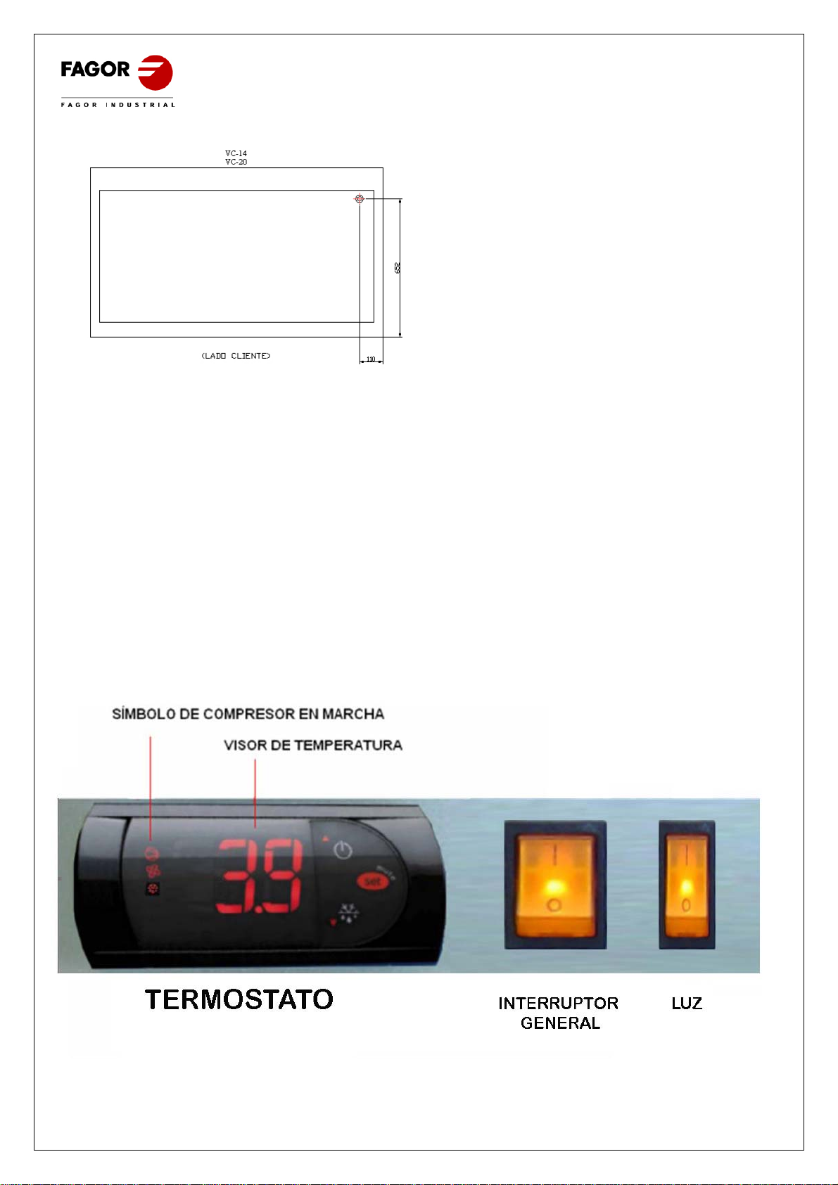
Comprobar que llega corriente a la vitrina observando que el interruptor general está
encendido.
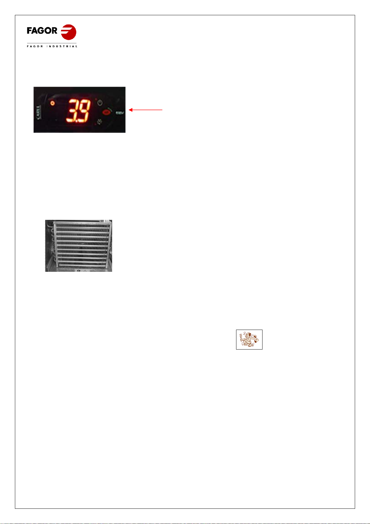
b) En caso de temperatura insuficiente
Comprobar que no existe cerca una fuente de calor y que no está taponada la salida de aire
del condensador.

7
Comprobar que el punto de corte del termostato está en un valor cercano a +2ºC/+8ºC,
para comprobarlo pulse la tecla “set” de su termostato una vez y suéltelo.
Comprobar que la temperatura ambiente no esté por encima de +32C (25ºC para vitrinas
Sushi(S)), que es la temperatura máxima de funcionamiento del aparato.
Comprobar que el tiempo transcurrido desde la carga de género es suficiente para enfriar los
productos.
Comprobar que el condensador está limpio: Ha de tener presente que cuanto más limpio esté
el equipo frigorífico, más ahorro de energía, en especial el aleteado del condensador. La
frecuencia vendrá determinada en función de las características del local. En caso de estar
sucio ha de llamar al servicio técnico para su limpieza.
Condensador limpio
c) En caso de ruidos extraños o excesivos
Comprobar la nivelación del mueble y que las puertas cierran bien.
Comprobar que no haya ningún objeto rozando con algún elemento móvil del frigorífico.
3.2 MANTENIMIENTO ESPECIAL
A efectuar exclusivamente por personal técnico cualificado
Limpieza del condensador: Al limpiar se tendrá cuidado de no doblar las aletas de aluminio
del condensador, ya que de hacerlo, no pasaría el aire y no condensaría, provocando serios
daños al equipo y quedando fuera de garantía su reparación.
Comprobar que las condiciones de temperatura del local no sean superiores a las indicadas
para su vitrina.
Sí la ventilación no es suficiente, la garantía quedará anulada.
No desmontar la protección de los elementos móviles, sin previamente haber desconectado
de la red eléctrica.
Tomar las precauciones necesarias antes de acceder a la zona de la unidad condensadora,
por la existencia de temperaturas elevadas en algunos elementos, y el consiguiente riesgo de
quemaduras.
Si el cable flexible o cordón de alimentación está dañado, ha de ser sustituido por el
fabricante, servicio post-venta o personal técnico autorizado con el fin de evitar riesgos.
En caso de sustitución ha de colocar de nuevo el terminal tierra en su posición.
Si necesita cambiar algún cable nunca debe disminuir la sección.
Las conexiones eléctricas se realizan mediante terminales faston de 6.35mm protegidas con
fundas.
Una vez corregido se ha de cerrar la puerta del cuadro de mandos con su fijación.

8
INSTALLATION, USE AND MAINTENANCE
CONTENT
1INSTALLATION ...............................................................................................................................8
1.0LOCATION...............................................................................................................................8
1.1CASE CLEANING....................................................................................................................9
1.2Connection..............................................................................................................................9
1.3SIGNBOARD..........................................................................................................................10
1.4Start up.................................................................................................................................12
2GUIDELINE FOR USE.................................................................................................................13
2.0INSTRUCTION FOR USE.....................................................................................................13
2.1PRECAUTION........................................................................................................................13
3MAINTENANCE.............................................................................................................................13
3.0CLEANING TO BE DONE BY THE OPERATOR.................................................................13
3.1Check machine ....................................................................................................................13
3.2SPECIAL MAINTENANCE....................................................................................................14
Before starting the display case, we would like to thanks you for the trust showed, purchasing this
refrigerated Display case. We advise you to read and follow the detailed instructions.
This user manual is useful to get any required information for refrigerated display case ´s
installation, use and maintenance.
OPERATIONAL TESTS
Your display case is ready to come correctly into operation and have been checked and certified by
a rigorous quality control test.
NB: The pictures from this manual can only be considered like an example and may not correspond
to its own product.
1 INSTALLATION
1.0 LOCATION
The refrigerated display case cannot overturn. Please remove the packing except the pallet. To
move it to the required location, you can use a pallet truck, or a lift truck to pick it up carefully in
order not to overturn it.
Position the unit in a dry, well-ventilated place away from heat sources or any vibration, in order to
avoid the refrigerator fan to absorb some materials which can deposit into the condenser fins,
reducing the system efficiency.
Remove the pallet, carefully to avoid damaging the display case. The unit should be set on a level
an firm place , screwing and unscrewing the legs of the display case.

9
1.1 CASE CLEANING
When you have your display case well located, you must clean it.
The first cleaning must be made with water and a neutral washing up liquid. When cleaned and dry , put the
accessories in the right place.
The cleaning of the external part of the equipment must be made daily with a dampened clean cloth. You cannot
use any abrasive substance or with any chlorine.
1.2 Connection
GENERAL
Before plug in the refrigerated display case, check that the voltage and frequency of the electric
power are the same of the ones pointed out in the features of the equipment.
BE CARREFUL , THE ELECTRICAL SYSTEM TO CONNECT THE DISPLAY CASE MUST HAVE A
GROUNDED SOCKET, AS WELL AS THERMOMAGNETIC PROTECTION AND DIFFERENTIAL
BREAKER.
Check that the wire section is available for the required electrical consumption.
The socket must be likely Schuko´s one cause the cable sleeve of your display case is from this
brand, (also known as F type or CEE 7/4”), with terminals of 4,8mm and grounded socket.
It´s forbidden to extend this cable sleeve for security reasons.
No insert anything through the fan grille or the area of the fridge equipment.
The place to put the unit must be on level and firm.
When starting the display, please get sure that there is not any heat source closer.
For correct operation of all the fridge equipments components it’s very important having the air
intake free of any blockage.
No put the equipment in the open air.
You will find enclose the display cases table consumption to check the protection.
REFRIGERATED
DISPLAY VOLTAGE INTENSITY
(A) CONSUMPTIO
N
(W)
FUSES
(GL o AM)
RESIDUAL
CURRENT
VTP-139 230V 50 Hz 1.5 345 2 30mA
VTP-175 230V 50 Hz 1.6 368 2 30mA
VTP-139-R 230V 50 Hz 1.5 345 2 30mA
VTP-175-R 230V 50 Hz 1.6 368 2 30mA
VTP-139-S 230V 50Hz 1.5 345 2 30mA
VTP-175-S 230V 50Hz 1.6 368 2 30mA
A: REGULATION SCREW
Turning to the right to go down the display case.
Turning to the left to go up.

10
There are others versions 220v 60Hz and 115v 60Hz.
Anyway, anta t request ,Display cases , can be delivered with cables sleeves type H (UK) y
type B (America)
1.3 SIGNBOARD
SIGNBOARD EXPLANATION
NB : This signboard is only an example.
REFRIGERATED DISPLAY CASES EXTERNALS DIMENSIONS IN mm.
TYPE DIMENSIONS
LENGTH WIDTH HEIGHT
VTP-139 1386 407 252
VTP-175 1737 407 252
VTP-139-R 1386 407 252
VTP-175-R 1737 407 252
VTP-139-S 1368 407 252
VTP-175-S 1737 407 252
REFRIGERATED DISPLAY VOLTAGE INTENSITY
(A) CONSUMPTION
(W) FUSES
(GL o AM)
RESIDUAL CURRENT
MI – 135 230V 50 Hz 1 178 2 30mA
MI – 150 230V 50 Hz 1 178 2 30mA
MI – 180 230V 50 Hz 1,1 213 2 30mA
MI – 202 230V 50 Hz 1,1 213 2 30mA
MI – 225 230V 50 Hz 1,1 213 2 30mA
MI – 255 230V 50 Hz 1,1 213 2 30mA
REFRIGERATED DISPLAY VOLTAGE INTENSITY
(A) CONSUMPTION
(W) FUSES
(GL o AM)
RESIDUAL CURRENT
VC-14-I 230V 50 Hz 2.7 616 4 30mA
VC-14-M 230V 50 Hz 2.7 616 4 30mA
VC-20-I 230V 50 Hz 3.0 704 4 30mA
VC-20-M 230V 50 Hz 3.0 704 4 30mA
VM-100-I 230V 50 Hz 1.7 396 2 30mA
VM-100-M 230V 50 Hz 1.7 396 2 30mA
VM-135-I 230V 50 Hz 1.7 396 2 30mA
VM-135-M 230V 50 Hz 1.7 396 2 30mA
NUMBER DESCRIPTION
1 MANUFACTURER
2 TYPE
3 SERIAL NEMBER
4 FRIDGE POWER EN WATT
5 VOLTAGE
6 FREQUENCY
7 INTENSITY
8 REFRIGERANT GAS
9 GRAMS OF REFRIGERANT GAS
10 CLIMATIC CLASS (N=4)
11 NORMS

11
TYPE DIMENSIONS
LENGTH WIDTH LENGTH
MI – 135 1340 336 236
MI – 150 1496 336 236
MI – 180 1790 336 236
MI – 202 2019 336 236
MI – 225 2240 336 236
MI – 255 2546 336 236
MI – 135 cúpula 1340 336 436
MI – 150 cúpula 1496 336 436
MI – 180 cúpula 1790 336 436
MI – 202 cúpula 2019 336 436
MI – 225 cúpula 2240 336 436
MI – 255 cúpula 2546 336 436
TYPE DIMENSIONS
LENGTH WIDTH LENGTH
VC-14-I 1380 800 1075
VC-14-M 1380 800 1075
VC-20-I 1980 800 1075
VC-20-M 1980 800 1075
VM-100-I 983 570 1120
VM-100-M 983 570 1120
VM-135-I 1333 570 1120
VM-135-M 1333 570 1120
DRAIN PLACEMENT EMERGENCY MEASURES

12
VC-14
VC-20
1.4 Start up
Alter clearing the display case, connect it to the electrical network and put the switch on or
en I, then the switch must be lighted.
3 minutes after switch on, the compressor led must be permanent lighted.
At the beginning, the indicated temperature in the display will be considered like the room
temperature. The value will be go down as the equipment go along with the closed doors
until the refrigerated value.
The refrigerated display must running until the working temperature before loading it.
CONTROL PANEL WITH SWITCH AND THERMOSTAT
COMPRESOR ENABLE
TEMPERATURE READOUT
TERMOSTAT GENERAL LIGHT
SWITCH

13
2 GUIDELINE FOR USE
The display cabinet acquired is intended for the temporary exhibition of food. We recommend no
insert hot food or any hot receptacle, as well as chemicals, corrosive products, and medicine.
Avoid unsuitable use of the display cabinet case. For a secure and efficient operation, be sure to
follow the instructions below:
2.0 INSTRUCTION FOR USE
1) Do not leave foods in the display cabinet after service hours, or they may dry or spoil.
It is advisable to disconnect and clean the cabinet daily after their service. Foods that
should not dry must be covered or wrapped up in a plastic film.
2) Store only pre-refrigerated items in the display cabinet. It takes longer for foods to cool
in the display cabinet than in a refrigerator.
3) Don´t open so many times the doors and above all, don´t let it open. The interior
temperature may rise, resulting in food deterioration.
4) The ambient temperature should not exceed 32 ºC (25ºC for showcases Sushi (S)). The
cooling performance may be reduced, helping to food spoilage.
2.1 PRECAUTION
1) All the external surface is made in glass, so be careful when placing something above the
equipment in order to avoid impacts (breakage glass).
2) In case of damage, breakdown, malfunction, don´t move to the equipment barefoot,
above a wet floor and with wet hands.
3 MAINTENANCE
In this point you will find any information’s about the cleaning to make, as well as un brief
machine test before calling technical support. We hope that it will be helpful.
3.0 CLEANING TO BE DONE BY THE OPERATOR.
Observe safe practice by disconnecting all electrical supply switching off the display before cleaning it.
The refrigerated display cases have drainpipe to make easy the cleaning, and exit of any kind of liquids coming
from the food storage. During the cleaning operation you should get the drainpipe plug out, clean it, in order to
avoid the obstruction of any solid elements carrying by the water.
3.1 Check machine
Before calling the technical support you can make a check. Sometimes, some cases of failures
Can be settle by the operator.
You will find below some example:
a) The refrigerated Display case is out of order.
Check that there is electrical supply watching that the general switch is on.
b) The temperature is not enough
Check that there is not any heat source closer, and the condenser exit outlet is not blocked

14
Check that the thermostat cut-off point have a temperature closer to +2ºC/+8ºC. Press the
SET key and release it.
Check that the ambient temperature is not over 32 ºC (25ºC for showcases Sushi (S)) which
is the maximum temperature value for your refrigerated display case operating.
Check that the elapsed time since the load of the food is enough to allow a correct food
cooling.
Check that the condenser is cleaned. The more cleaned is the refrigeration unit, the more
energy savings you get, especially the condenser fins. The cleaning schedule will be relation
to the local conditions. You should call technical support to clean the condenser.
CLEANED CONDENSER.
c) EXCESSIVES AND
STRANGES NOISES
Check the set on a level of the equipment and that the doors are closed.
Check that there is not something scraping against some part of the refrigerated display
case.
3.2 SPECIAL MAINTENANCE
Can be made only by a qualified and experience person.
Condenser clearing: Carefully cleaning it in order not to bend the aluminium condenser fins.
It would cause damages in the equipment and will void your warranty.
Check that the ambient temperature is not upper than the ones off your equipment.
In case of stuffiness, bad ventilation will void the product’s warranty.
Don’t remove any protection part of the machine before disconnecting all electrical supply.
Act with caution when accessing to the condenser unit, for the high temperatures of some
components to avoid burn.
If the flexible cable or the electrical supply cable is damaged, it only can be changed by the
manufacturer, by after sales service, or any qualified technical and authorized or official
person.
In case of substitution and for safety reasons the unit must be properly earthed one more
time. Check and make sure that the outlet is properly grounded.
Should you change any wire, cable, please don´t decrease the section of the wire.
The electrical connections are made by a fast on terminal 6.35 mm protected by a cover.
When the maintenance operation is over please close the front panel door’s with the
mountings.
This manual suits for next models
23
Table of contents
Languages: