Greenlee / A Textron Company 4455 Boeing Dr. • Rockford, IL 61109-2988 USA • 815-397-7070
5
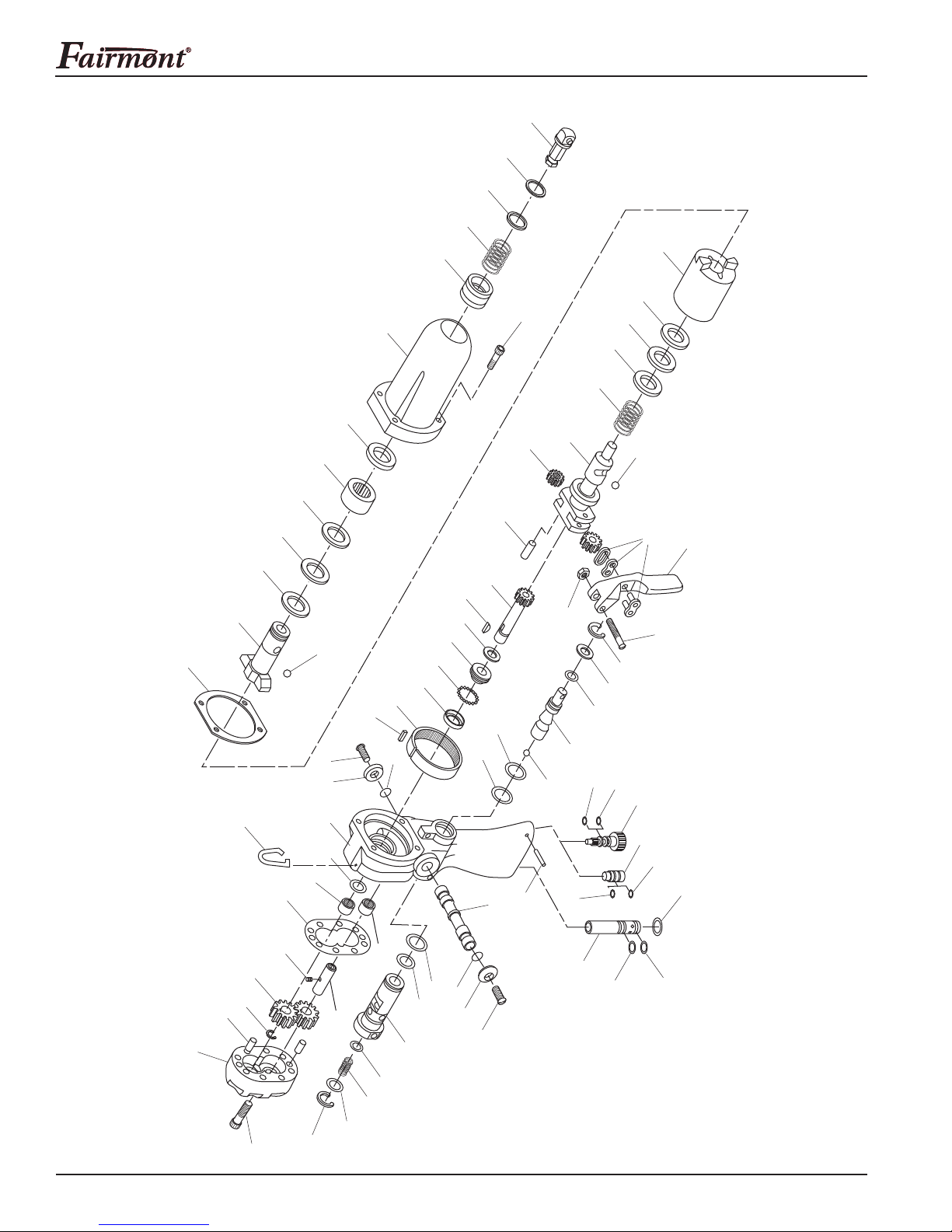
H8500A Hydraulic Impact Wrench, Drill and Screwdriver
Disassembly
Complete disassembly of the tool is not recommended.
If a complete overhaul is necessary, return the tool to
your nearest Fairmont Authorized Service Center.
The disassembly procedure is divided into sections of
the tool. Disassemble only the section(s) necessary to
complete the repair.
Disassemble the tool on a at, clean surface. Take care
not to lose or damage any parts that may fall free during
disassembly.
Quick-Change Chuck
1.
Remove the adapter drive shank (73) from the chuck.
2. Remove the lock ring (72), ring (71), and spring (70).
Note: To prevent the loss of any steel balls, perform
the next step over a clean, empty container.
3. Slide the sleeve (69) off and remove the three steel
balls (68).
Case Components
1. Scribe a line across the case (63) and handle (1) to
align the parts correctly during assembly.
2. Remove four cap screws (67) and remove the case
(63) from the handle. Remove the gasket (66).
3. Remove the anvil (60), thrust bearing (61), and thrust
races (62) from the case. If necessary, press the
roller bearing (64) and seal (65) from the case.
4. Remove the hammer assembly (51–59) from the
handle assembly.
5. If the hammer assembly components require
disassembly, compress the hammer (55) and carrier
pinion (51) together in a vise or a press. Remove the
two steel balls (59). Release the assembly from the
vise or press.
6. Remove the hammer from the carrier pinion.
Remove the thrust races (57), thrust bearing (56),
and spring (58). Drive out the dowel pins (54) to
remove the gears (52).
7. Remove the ring gear (4) and the dowel pin (5) from
the handle assembly.
Motor
1. Scribe a line across the motor cap (47) and handle
(1) to align the parts correctly during assembly.
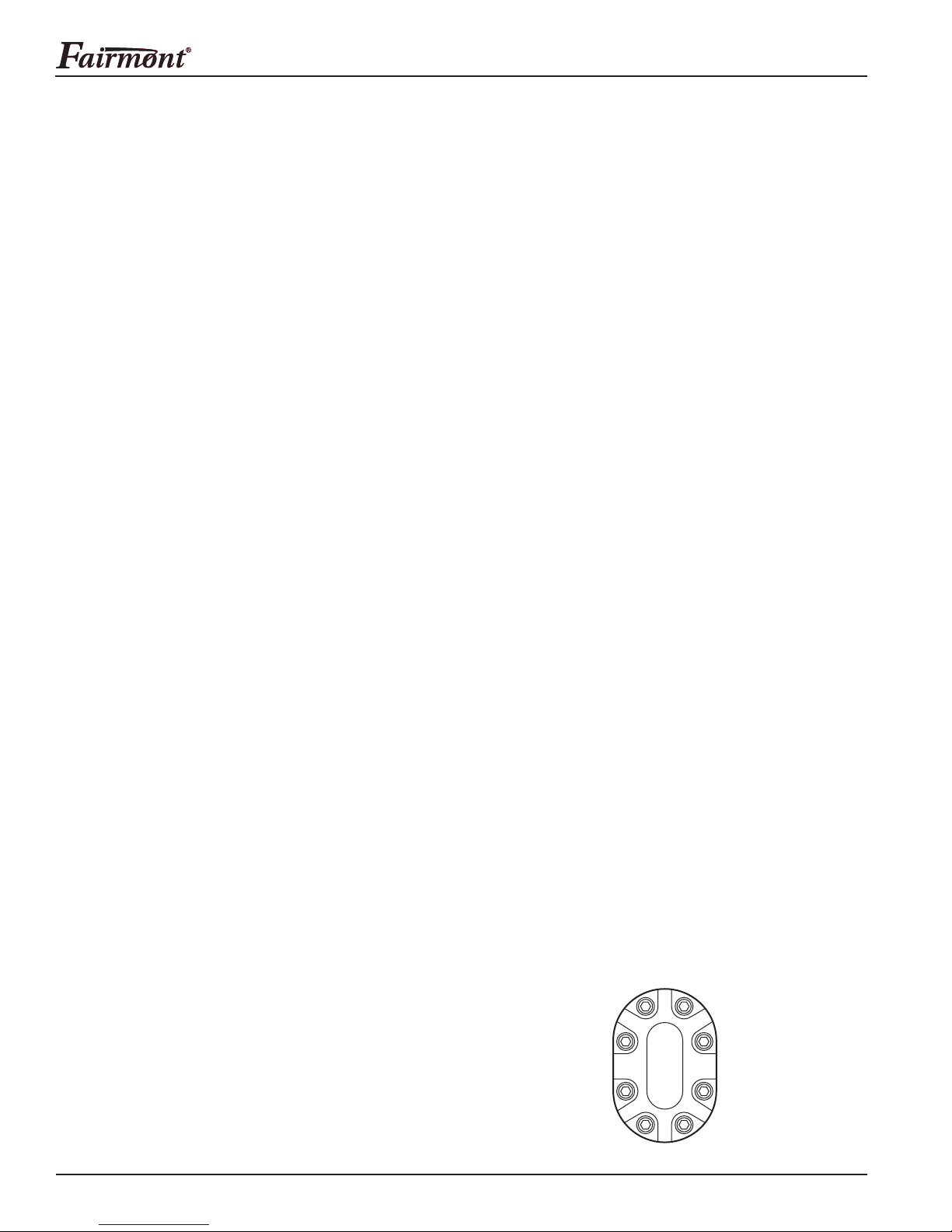
2. Remove eight cap screws (49) and the cap from the
handle. Remove the gasket (46) and, if necessary,
the dowel pins (45).
3. Pull the idler shaft (43) with gear (40) from the
handle. If necessary, remove the drive pin (44).
4. Remove the retaining ring (42), gear (40), and
Woodruff key (41) from the drive shaft (39). Pull the
drive shaft from the handle.
Note: To prevent the loss of any steel balls, perform
the next step over a clean, empty container.
5. Remove the inner race (38) and the 18 steel balls
(37) from the handle.
6. Use an O-ring tool to remove the O-ring (2) without
removing the needle bearing (3).
Trigger, Control Spool, and Super Spool™ Sleeve
1. Remove the retaining ring (25) and cap (24) from the
Super Spool sleeve (19). Remove the spring (29).
2. Remove the connecting link (33) from the trigger (32)
and control spool (26). Remove one nut (35) and one
machine screw (34) from the trigger (32). Remove
the trigger.
3. Remove the retaining ring (31) and washer (30).
Remove the control spool (26) from the Super Spool
sleeve (19). Remove the O-ring (27) from the control
spool (26). Remove the ball (28) from the control
spool.
4. Remove the external retaining ring (22) from the
Super Spool sleeve. Remove the sleeve from the
handle.
5.
Remove the O-rings (20, 21, 23) from the Super Spool
sleeve. Remove the O-ring (18) from the handle.
Directional Spool
1. Remove the cap screws (17) and buttons (16) from
the directional spool (14).
2. Slide the directional spool partially out of the handle
to expose either O-ring (15). Remove the exposed
O-ring. Remove the spool by pushing it back
through the handle. Remove the other O-ring.
Note: Attempting to force the directional spool
through the bore against the O-ring will damage the
O-ring and could allow particles of O-ring to get into
the motor.
Flow Control Cartridge
1. Remove the retaining ring (9). Remove the ow
control cartridge (6) from the handle.
2. Remove the O-rings (7, 8) from the cartridge.
Do not attempt to repair the ow control cartridge.
It contains no replaceable parts.
Failure to observe this warning can result in severe
injury or death.
Adjustable Torque Output Screw
or Non-Adjustable Torque Output Plug
1. Remove the roll pin (13) from the handle. Twist the
screw (10) or plug (74) counterclockwise to remove
it from the handle.
2. Remove the O-ring (11) and backup ring (12).