Farfisa VIP 600 User manual

FARF1S/1
VIP
600
IMPORTANT:
in
any
correspondence
concerning
this
INSTRUMENT
ALWAYS
INCLUDE
MODEL
AND
SERIAL
NUMBERS!
PARTS
ORDERING
-
When
ordering
parts
be sure
to
include
the
following
information:
1.
Model
and
serial
Number
of
instrument.
2.
Part
Code;
w;
3.'A
description
of
the
Part:
>
?
v
""
*
4
Specify
how
you
want
the
part
shipped.
FARFISA
COMPANY
-
WHOSE
POLICY
IS
CONSTANTLY
DIRECTED
TO
IMPROVEMENTS
AND
NEW
DEVELOPMENTS
-
RESERVES
THE
RIGHT
TO
CHANGE
SPECIFICATIONS,
DESIGNS,
PRICES,
MODELS
AND
TO
DISCONTINUE
MODELS
WITHOUT
NOTICE
AND
LIABILITY.
Scan by Manual Manor
http://www.markglinsky.com/ManualManor.html
.
INDICE
TABLE
OF
CONTENTS
CARATTERISTICHE
PRINCIPI
Dl
FUNZIONAMENTO
TARATURE
RICERCA
GUASTI
....
COME
APRIRE
LO
STRUMENTO
SCHEMA
ELETTRICO
Schema
a
blocchi
Oscillatore
-
Vibrato
-
Syntehslalom
Tabella
dei
divisori
Tabella
di
riferimento
Contattiera
manuale
superiore
Prefiltri
manuale
superiore
Filtri
Flauti
-
Sharps
Filtri
Percussion
-
Repeat
Contattiera
manuale
inferiore
Preamplificatore
-
Filtri
manuale
inferiore
Filtri
acuti
manuale
inferiore
Filtro
Wha-Wha
Alimentatore
-
Preamplificatore
Generale....
FOTOGRAFIE
E
PARTI
Dl
RICAMBIO
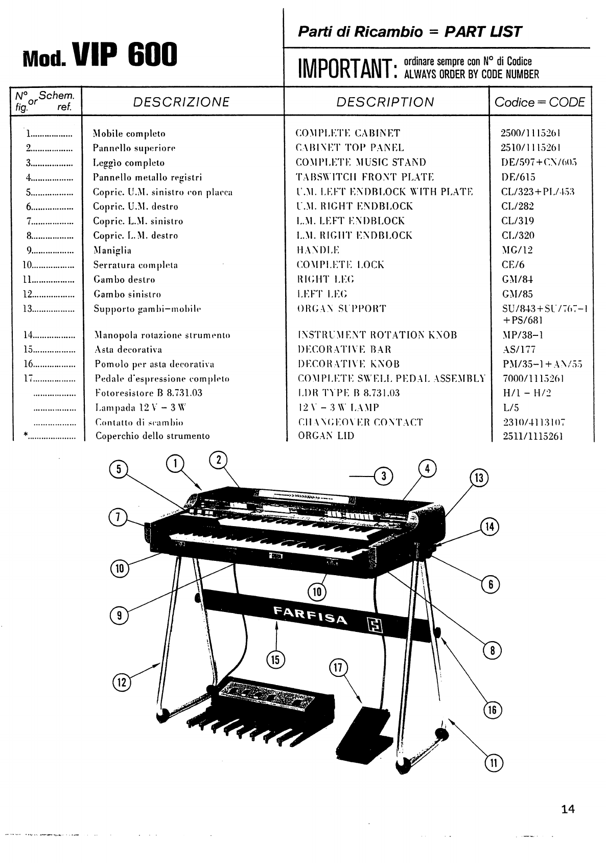
Mobile
completo
Schienale
-
Oscillatori
Tastiere
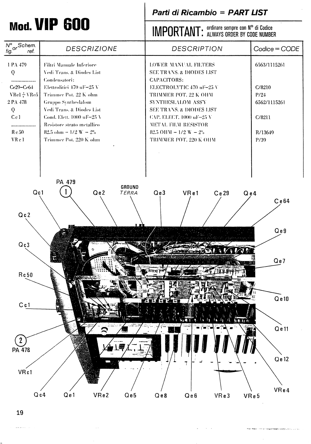
Filtri
manuale
inferiore
-
Syntheslalom
,
Filtri
Flauti
-
Sharps
-
Percussion
-
Repeat.
Contattiera
manuale
superiore
Preamplificatori
-
Volumi
-
Vibrato
Illustrazione
generale
Gruppo
base
porta
prese
Alimentatore
Gruppo
Wha-Wha
Contattiera
manuale
inferiore
TRANSISTORS
(Q)
&
DIODES
(D)
LIST
....
PEDALIERA
PPS
132
DESCRIZIONI
SCHEMA
ELETTRICO
FOTOGRAFIE
E
PARTI
Dl
RICAMBIO
Pedaliera
completa
Gruppo
Sustain
TRANSISTORS
(Q)
&
DIODES
(D)
LIST....
SPECIFICATIONS
3
THEORY
OF
OPERATION
4
ADJUSTMENTS
7
TROUBLESHOOTING
GUIDE
8
HOW
TO
OPEN
THE
INSTRUMENT
11
SCHEMATIC
DIAGRAM
Block
diagram
DWG
1
Oscillator
-
Vibrato
-
Syntheslalom
DWG
2
Dividers
Table
DWG
3
Table
of
reference
DWG
4
Upper
manual
Keyswitch
DWG
5
Upper
manual
prefilters
DWG
6
Flutes
-
Sharps
filters
DWG
7
Percussion
-
Repeat
filters
DWG
8
Lower
manual
keyswitch
DWG
9
Preamplifier
-
Lower
manual
filters
DWG
10
Lower
manual
treble
filters
DWG
11
Wha-Wha
filter
DWG
12
Power
Supply
-
General
Preamplifier
DWG
13
PHOTOGRAPHS
AND
PARTS
LIST
Cabinet
assembly
14
Back
Cover
-
Oscillators
15
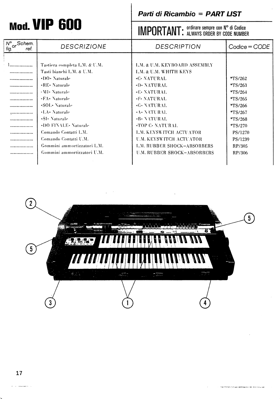
Keyboards
17
Lower
manual
filters
-
Syntheslalom
19
Flutes
-
Sharps
-
Percussion
-
Repeat
filters
20
Upper
manual
keyswitch
21
Volume
-
Vibrato
preamplifiers
22
General
illustration
23
Socket
assembly
24
Power
Supply
25
Wha-Wha
assembly
26
Lower
manual
keyswitch
27
TRANSISTORS
(Q)
&
DIODES
(D)
LIST
28
PPS
132
PEDALBOARD
DESCRIPTION
31
SCHEMATIC
DIAGRAM
DWG
1
PHOTOGRAPHS
AND
PARTS
LIST
Pedalboard
assembly
32
Sustain
assembly
33
TRANSISTORS
(Q)
&
DIODES
(D)
LIST
34
Scan by Manual Manor
http://www.markglinsky.com/ManualManor.html

FARFISA
VIP
600
Scan by Manual Manor
http://www.markglinsky.com/ManualManor.html

CARATTERISTICHE
SPECIFICATIONS
MANUALE
SUPERIORE
49
tasti
DO-DO.
FLUTES
6
registri
a
drawbar:
«16'»
-
«8'»
-
«5i/3'»
-
«4'»
-
«22/3'»
-
«2».
SHARPS
3
registri
a
drawbar:
«4'»
-
«22/3'»
-
«2'».
PERCUSSION
5
registri
a
drawbar:
«8'»
-
«5i/3'»
-
«22/3'»
-
«2'»
-
decay.
Registro
Phrasing.
REPEAT
Registro
On/Off
e
controllo
rotativo
di
velocita.
MANUALE
INFERIORE
61
tasti
DO-DO.
5
registri
piu
1
per
il
controllo
decay.
EFFETT1:
Piano
-
HonkieTonk
-
Harpsichord
-
Banjo
-
Trombone
-
Violin
-
Trumpet
-
Horn.
WHA
WHA
e
relativo
cursore
per
regolazione
lunghezza.
MULTI
WHA-WHA
e
relativo
cursore
per
rego
lazione
velocita.
MANUAL
BASS
&
CHORDS
Registro
Keyboard
Splitting
per
trasformare
le
prime
20
note
nella
sezione
Manual
Bass
&
Chords.
3
registri
per
effetti
Bass
-
Bass
Guitar
-
String
Bass.
Registro
Attack.
Registro
Chords.
CONTROLLI
GENERALI
Regolatori
di
volume
a
cursore
per
Manual
Bass
-
Chords
- Lower
Manual
-
Flutes
-
Sharps
-
Percussion..
Vibrato
-
Vibrato
Delay.
Syntheslalom
con
potenziometro
per
il
controllo
del
Range
e
registro
a
drawbar
per
il
controllo
del
Timer.
Pedale
di
espressione
a
fotocellula
con
incorporato
I'interruttore
per
il
controllo
del
Sustain
dei
registri
del
manuale
inferiore.
COLLEGAMENTI
Presa
jack
per
separare
il
manuale
inferiore
e
il
Manual
Bass.
Presa
per
pedaliera
opzionale
PPS
132.
OPZIONALE
PEDALIERA
FARFISA
«PPS
132»
13
note
-
3
registri
voci:
Bass
16'
-
Bourdon
161
-
Bass
8\
Sustain.
Controllo
di
volume.
UPPER
MANUAL
49
keys
DO-DO.
FLUTES
6
drawbar
tabs:
«16f»
-
«8'»
-
5i/3'»
-
«4'»
-
«32/3'
-
«2».
SHARPS
3
drawbar
tabs:
«4'»
-
«22/3'»
-
«2'».
PERCUSSION
5
drawbar
tabs:
«8'»
-
«5i/3'»
-
«22/3'»
-
«2'»
-
decay.
Phrasing
tab.
REPEAT
On/Off
tab
and
rotative
speed
control.
LOWER
MANUAL
61
keys
DO-DO.
5
tabs
plus
1
for
decay
control.
EFFECTS:
Piano
-
Honkie
Tonk
-
Harpsichord
-
Banjo
-
Trombone
-
Violin
-
Trumpet
-
Horn.
WHA WHA
and
relative
cursor
for
length
regulation.
MULTI
WHA-WHA
and
relative
cursor
for
speed
regulation.
MANUAL
BASS
&
CHORDS
Keyboard
Splitting
tab
for
transforming
the
first
20
notes
into
Manual
Bass
&
Chords
section.
3
tabs
for
Bass
-
Bass
Guitar
-
String
Bass
effects.
Attack
tab.
Chords
tab.
GENERAL
CONTROLS
Sliding
volume
control
for
Manual
Bass
-
Chords
-
Lower
Manual
-
Flutes
-
Sharps
-
Percussion.
Vibrato
-
Vibrato
Delay.
Syntheslalom
with
potentiometer
for
controlling
Range
and
drawbar
tab
for
controlling
Timer.
Photocell
expression
pedal
with
incorporated
switch
for
controlling
the
Sustain
of
the
lower
manual
tabs.
CONNECTIONS
Jack
plug
to
separate
the
lower
manual
and
the
Manual
Bass.
Plug
for
optional
pedalboard
PPS
132.
OPTIONAL
FARFISA
PEDALBOARD
«PPS
132»
13
notes
-
3
voice
tabs:
Bass
16'
-
Bourdon
16'
-
Bass
8'.
Sustain.
Volume
control.
Scan by Manual Manor
http://www.markglinsky.com/ManualManor.html

PRINCIPI
DI
FUNZIONAMENTO
THEORY
OF
OPERATION
GENERAZIONE
Le
12
note
dell'ottava
piu
acuta
sono
ottenute
da
12
oscillatori
R-C
che
generano
le
frequenze
piu
alte
di
cui
Porgano
dispone.
Le
note
di
tutte
le
altre
ottave
piu
basse
vengono
ottenute
per
successive
divisioni
per
due,
partendo
dalle
12
frequenze
cam-
pioni,
mediante
Putilizzazione
di
circuiti
divisori
integrati.
Le
note
cosi
ottenute
sono
disponibili
sulle
contat-
tiere
del
manuale
superiore
e
del
manuale
inferiore
e
sono
pronte
per
potere
essere
elaborate.
Direttamente
sugli
oscillatori
agiscono
due
effetti:
il
Vibrato
e
il
Syntheslalom.
II
Vibrato
e
costituito
da
un
oscillatore
sinusoidale
che
viene
usato
per
modulare
in
frequenza
i
12
oscillatori
campioni.
La
frequenza
del
Vibrato
viene
scelta
da
un
registro
a
drawbar;
I'inserzione
del
Vibrato
viene
attuata
dallo
stesso
drawbar.
II
Vibrato
Delay
permette
di
avere
il
Vibrato
con
un
ritardo
prefissato
dopo
che
sia
stato
premuto
un
qualsiasi
tasto
del
manuale
superiore.
Smettendo
di
suonare,
I'oscillatore
si
ferma
e
riparte
solamente
quando
si
preme
un
altro
tasto.
II
Syntheslalom
e
un
effetto
comandato
dal
circuito
della
Percussione
o
dal
circuito
del
Repeat.
Consiste
in
un
abbassamento
della
frequenza
degli
oscillatori
fino
ad
una
ottava
sotto
a
quella
nominale
e
il
ritorno
automatico
alia
frequenza
nominale.
II
grado
di
abbassamento
viene
regolato
dal
poten
ziometro
Range
ed
il
tempo
di
ritorno
alia
frequenza
nominale
dal
drawbar
Timer.
Quando
e
inserito
il
registro
Repeat
questo
spostamento
di
frequenza
e
continuo
e
la
velocita
e
continuo
e
la
velocita
e
comandata
dal
potenziometro
Repeat
Speed.
L'esclusione
dell'effetto
si
ottiene
azzerando
o
il
Timer
o
il
Range.
MANUALE
SUPERIORE
II
segnale
raccolto
dalle
barre
comuni
poste
sulla
contattiera
del
manuale
superiore
viene
portato
alle
piastre
delle
miscelazioni
e
dei
filtri.
Su
queste
piastre,
attraverso
filtri
di
tipo
passa
basso,
passa
gamma
e
passa
alto
vengono
ottenuti
i
timbri
dei
flauti,
degli
sharps
e
della
percussione.
I
segnali
dei
flauti
e
degli
sharps
cosi
ottenuti
vengono
portati,
dopo
essere
stati
preamplificati,
ai
rispettivi
drawbar
di
volume
generale.
Da
qui
al
preamplificatore
generale
di
uscita.
TONE
GENERATOR
The
12
notes
of
the
sharpest
octave
are
obtained
by
12
R-C
oscillators
which
generate
the
highest
frequencies
available
on
the
organ.
The
notes
of
all
the
other
lower
octaves
are
obtained
by
successive
divisions
by
two,
starting
from
the
12
master
frequencies,
through
the
use
of
I.C.
dividers.
The
notes
thus
obtained
are
available
on
the
upper
manual
and
lower
manual
keyswitches
ready
to
be
elaborated.
Two
effects
act
directly
on
the
oscillators:
Vibrato
and
Syntheslalom.
The
Vibrato
is
made
up
of
a
sinusoidal
oscillator
which
is
used
to
frequency
modulate
the
twelve
master
oscillators.
The
Vibrato
frequency
is
chosen
by
a
drawbar
tab,
the
same
drawbar
is
used
to
insertert
the
Vibrato.
The
Vibrato
Delay
gives
the
possibility
of
having
the
Vibrato
at
a
prefixed
delay
after
any
Upper
Manual
key
has
been
pressed.
On
stopping
playing,
the
oscillator
stops
and
restarts
only
when
another
key
is
pressed.
The
Syntheslalom
is
an
effect
which
is
controlled
either
by
the
Percussion
circuit
or
by
the
Repeat
circuit.
It
consists
in
dropping
the
oscillator
frequency
to
an octave
lower
than
the
nominal
frequency
and
the
automatic
return
to
the
nominal
frequency.
The
grade
of
the
drop
is
controlled
by
the
Range
potentiometer
and
the
length
of
time
of
return
to
the
nominal
frequency
by
the
Timer
drawbar.
When
the
Repeat
tab
is
inserted
this
frequency
shifting
is
continuous
and
the
speed
is
controlled
by
the
Repeat
speed
potentiometer.
By
taking
the
Timer
or
the
Range
fully
c.c.w.
the
effect
is
excluded.
UPPER
MANUAL
The
signal
picked
up
by
the
common
bars
located
on
the
Upper
Manual
contactboard
is
taken
to
the
mixing
and
filter
boards.
Flute,
sharp
and
percussion
timbres
are
obtained
on
these
boards
through
filters
of
the
low
pass,
band
pass
and
high
pass
type.
The
flute
and
sharp
signals
thus
obtained
are
taken,
after
having
been
preamplified,
to
the
respective
general
volume
drawbar
and
from
here
to
the
general
output
preamplifier.
Scan by Manual Manor
http://www.markglinsky.com/ManualManor.html
PRINCIPI
DI
FUNZIONAMENTO
THEORY
OF
OPERATION
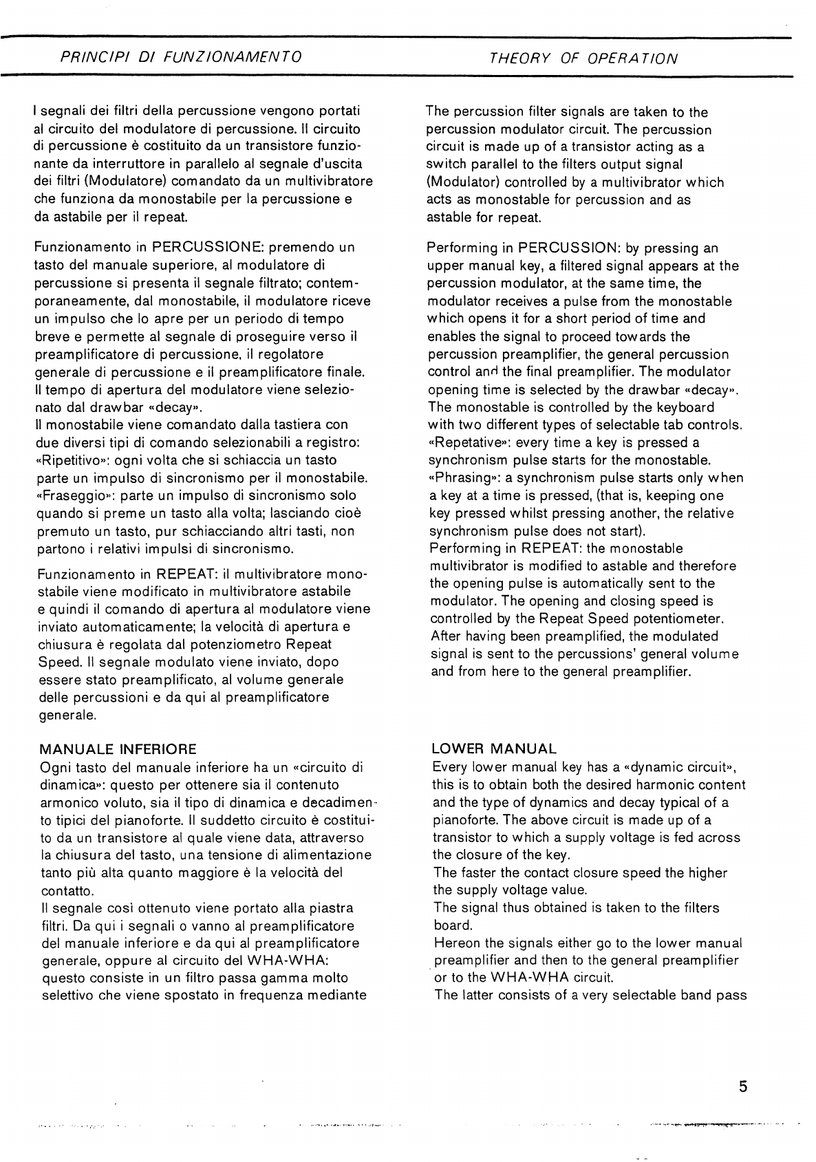
I
segnali
dei
filtri
della
percussione
vengono
portati
al
circuito
del
modulatore
di
percussione.
II
circuito
di
percussione
e
costituito
da
un
transistore
funzio-
nante
da
interruttore
in
parallelo
al
segnale
d'uscita
dei
filtri
(Modulatore)
comandato
da
un
multivibratore
che
funziona
da
monostabile
per
la
percussione
e
da
astabile
per
il
repeat.
Funzionamento
in
PERCUSSIONE:
premendo
un
tasto
del
manuale
superiore,
al
modulatore
di
percussione
si
presenta
il
segnale
filtrato;
contem-
poraneamente,
dal
monostabile,
il
modulatore
riceve
un
impulso
che
lo
apre
per
un
periodo
di
tempo
breve
e
permette
al
segnale
di
proseguire
verso
il
preamplificatore
di
percussione,
il
regolatore
generale
di
percussione
e
il
preamplificatore
finale.
II
tempo
di
apertura
del
modulatore
viene
selezio-
nato
dal
drawbar
«decay».
II
monostabile
viene
comandato
dalla
tastiera
con
due
diversi
tipi
di
comando
selezionabili
a
registro:
«Ripetitivo»:
ogni
volta
che
si
schiaccia
un
tasto
parte
un
impulso
di
sincronismo
per
il
monostabile.
«Fraseggio»:
parte
un
impulso
di
sincronismo
solo
quando
si
preme
un
tasto
alia
volta;
lasciando
cioe
premuto
un
tasto,
pur
schiacciando
altri
tasti,
non
partono
i
relativi
impulsi
di
sincronismo.
Funzionamento
in
REPEAT:
il
multivibratore
mono
stabile
viene
modificato
in
multivibratore
astabile
e
quindi
il
comando
di
apertura
al
modulatore
viene
inviato
automaticamente;
la
velocita
di
apertura
e
chiusura
e
regolata
dal
potenziometro
Repeat
Speed.
II
segnale
modulato
viene
inviato,
dopo
essere
stato
preamplificato,
al
volume
generale
delle
percussioni
e
da
qui
al
preamplificatore
generale.
MANUALE
INFERIORE
Ogni
tasto
del
manuale
inferiore
ha
un
«circuito
di
dinamica»:
questo
per
ottenere
sia
il
contenuto
armonico
voluto,
sia
il
tipo
di
dinamica
e
decadimen-
to
tipici
del
pianoforte.
II
suddetto
circuito
e
costitui
to
da
un
transistore
al
quale
viene
data,
attraverso
la
chiusura
del
tasto,
una
tensione
di
alimentazione
tanto
piu
alta
quanto
maggiore
e
la
velocita
del
contatto.
II
segnale
cosi
ottenuto
viene
portato
alia
piastra
filtri.
Da
qui
i
segnali
o
vanno
al
preamplificatore
del
manuale
inferiore
e
da
qui
al
preamplificatore
generale,
oppure
al
circuito
del
WHA-WHA:
questo
consiste
in
un
filtro
passa
gamma
molto
selettivo
che
viene
spostato
in
frequenza
mediante
The
percussion
filter
signals
are
taken
to
the
percussion
modulator
circuit.
The
percussion
circuit
is
made
up
of
a
transistor
acting
as a
switch
parallel
to
the
filters
output
signal
(Modulator)
controlled
by
a
multivibrator
which
acts
as
monostable
for
percussion
and
as
astable
for
repeat.
Performing
in
PERCUSSION:
by
pressing
an
upper
manual
key,
a
filtered
signal
appears
at
the
percussion
modulator,
at
the
same
time,
the
modulator
receives
a
pulse
from
the
monostable
which
opens
it
for
a
short
period
of
time
and
enables
the
signal
to
proceed
towards
the
percussion
preamplifier,
the
general
percussion
control
anH
the
final
preamplifier.
The
modulator
opening
time
is
selected
by
the
drawbar
«decay».
The
monostable
is
controlled
by
the
keyboard
with
two
different
types
of
selectable
tab
controls.
«Repetative»:
every
time
a
key
is
pressed
a
synchronism
pulse
starts
for
the
monostable.
«Phrasing»:
a
synchronism
pulse
starts
only
when
a
key
at
a
time
is
pressed,
(that
is,
keeping
one
key
pressed
whilst
pressing
another,
the
relative
synchronism
pulse
does
not
start).
Performing
in
REPEAT:
the
monostable
multivibrator
is
modified
to
astable
and
therefore
the
opening
pulse
is
automatically
sent
to
the
modulator.
The
opening
and
closing
speed
is
controlled
by
the
Repeat
Speed
potentiometer.
After
having
been
preamplified,
the
modulated
signal
is
sent
to
the
percussions'
general
volume
and
from
here
to
the
general
preamplifier.
LOWER
MANUAL
Every
lower
manual
key
has
a
"dynamic
circuits
this
is
to
obtain
both
the
desired
harmonic
content
and
the
type
of
dynamics
and
decay
typical
of
a
pianoforte.
The
above
circuit
is
made
up
of
a
transistor
to
which
a
supply
voltage
is
fed
across
the
closure
of
the
key.
The
faster
the
contact
closure
speed
the
higher
the
supply
voltage
value.
The
signal
thus
obtained
is
taken
to
the
filters
board.
Hereon
the
signals
either
go
to
the
lower
manual
preamplifier
and
then
to
the
general
preamplifier
or
to
the
WHA-WHA
circuit.
The
latter
consists
of
a
very
selectable
band
pass
Scan by Manual Manor
http://www.markglinsky.com/ManualManor.html

PRINCIPI
DI
FUNZIONAMENTO
THEORY
OPERATION
un
comando
della
tastiera
inferiore.
Lai
frequenza
centrale
del
filtro
parte
da
circa
200
Hz
e
si
sposta
gradualmente
fino
a
2000
Hz
e
ritorna
a
200
Hz.
Questo
spostamento
oltre
che
comandato
dalla
tastiera
attraverso
un
multivibratore
monostabile
puo
essere
comandato
da
un
oscillatore
sinusoidaie:
in
questo
caso
il
filtro
si
sposta
automaticamente
e
I'escursione
continua
fino
a
quando
non
si
lascia
il
tasto.
II
segnale
in
uscita
dal
WHA-WHA
viene
portato
al
preamplificatore
del
manuale
inferiore
e
da
qui
al
preamplificatore
generale.
Le
prime
20
note
del
manuale
inferiore
possono
dare
inoltre
altre
prestazioni:
tirando
il
«drawbar»
«Keyboard
Splitting»
si
separa
la
tastiera
e
nella
sua
parte
sinistra
si
possono
avere
o
gli
effetti:
Bass,
Guitar
Bass,
String
Bass;
oppure
I'effetto
Chords.
I
segnali
prelevati
dai
rispettivi
punti
vanno
alia
piastra
filtri.
I
bassi
possono
seguire
lo
stesso
percorso
degli
acuti
(filtri
Wha-Wha
ecc...);
oppure
inserendo
il
drawbar
«Keyboard
Spiitting»
andare
nei
filtri
bassi
e
da
qui
al
preamplificatore
generale
d'uscita.
PEDALE
D'ESPRESSIONE
II
pedale
d'espressione
lavora
come
regolazione
di
volume
sul
preamplificatore
generale.
Esso
controlla
la
lunghezza
del
decadimento
dei
timbri
del
pianoforte,
banjo,
ecc.
ecc...
del
manuale
inferiore
variando
una
tensione
di
riferimento
dei
«circuiti
di
dinamica**
del
manuale
inferiore.
PRESA
CUFF1A
La
presa
cuffia
agisce
sul
preamplificatore
generale
generale:
quando
viene
inserito
il
jack
dall'organo
non
esce
alcun
segnale.
filter
shifted
in
frequency
through
a
lower
keyboard
control.
The
filter
central
frequency
starts
from
about
200
Hz
and
is
gradually
shifted
to
2000
Hz
and
returns
to
200
Hz.
This
shifting,
apart
from
being
controlled
from
the
keyboard
across
a
monostable
multivibrator,
can
be
controlled
by
a
sinusoidal
oscillator.
In
this
case
the
filter
shifts
automatically
and
continues
until
the
key
is
released.
The
WHA-WHA
output
feignal
is
taken
to
the
lower
manual
preamplifier
and
from
here
to
the
general
preamplifier.
Furthermore,
the
first
20
notes
of
the
lower
manual
has
other
features.
By
pulling
the
"Keyboard
Splitting**
drawbar,
the
keyboard
is
split,
that
is,
on
the
left
it
is
possible
to
obtain
either
Bass,
Guitar
Bass,
String
Bass
effects
or
the
Chords
effect.
The
signals
picked
up
from
their
respective
points
go
to
the
filters
board.
The
basses
can
follow
the
same
route
as
the
sharps
(Wha-Wha
filter,
etc.),
or
by
inserting
the
"Keyboard
Splitting**
drawbar,
they
can
go
to
the
bass
filters
and
from
here
to
the
general
output
preamplifier.
SWELL
PEDAL
The
swell
pedal
acts
as
volume
control
on
the
general
preamplifier.
It
controls
the
length
of
decay
of
the
lower
manual
timbres
i.
e.
piano,
banjo
etc.
etc...
varying
a
reference
voltage
on
the
lower
manual's
«dinamic
circuits**.
HEADPHONE
JACK
The
headphone
jack
acts
on
the
general
preamplifier.
When
the
jack
is
pluged
in,
there
is
no
output
signal
from
the
organ.
Scan by Manual Manor
http://www.markglinsky.com/ManualManor.html
TARATURE
ADJUSTMENTS
Tutte
le
tarature
sono
eseguite
in
fabbrica
percio
non
sono
necessarie
ulteriori
regolazioni.
Qualsiasi
intervento
all'interno
dello
strumento
dovra
essere
compiuto
da
tecnici
specializzati.
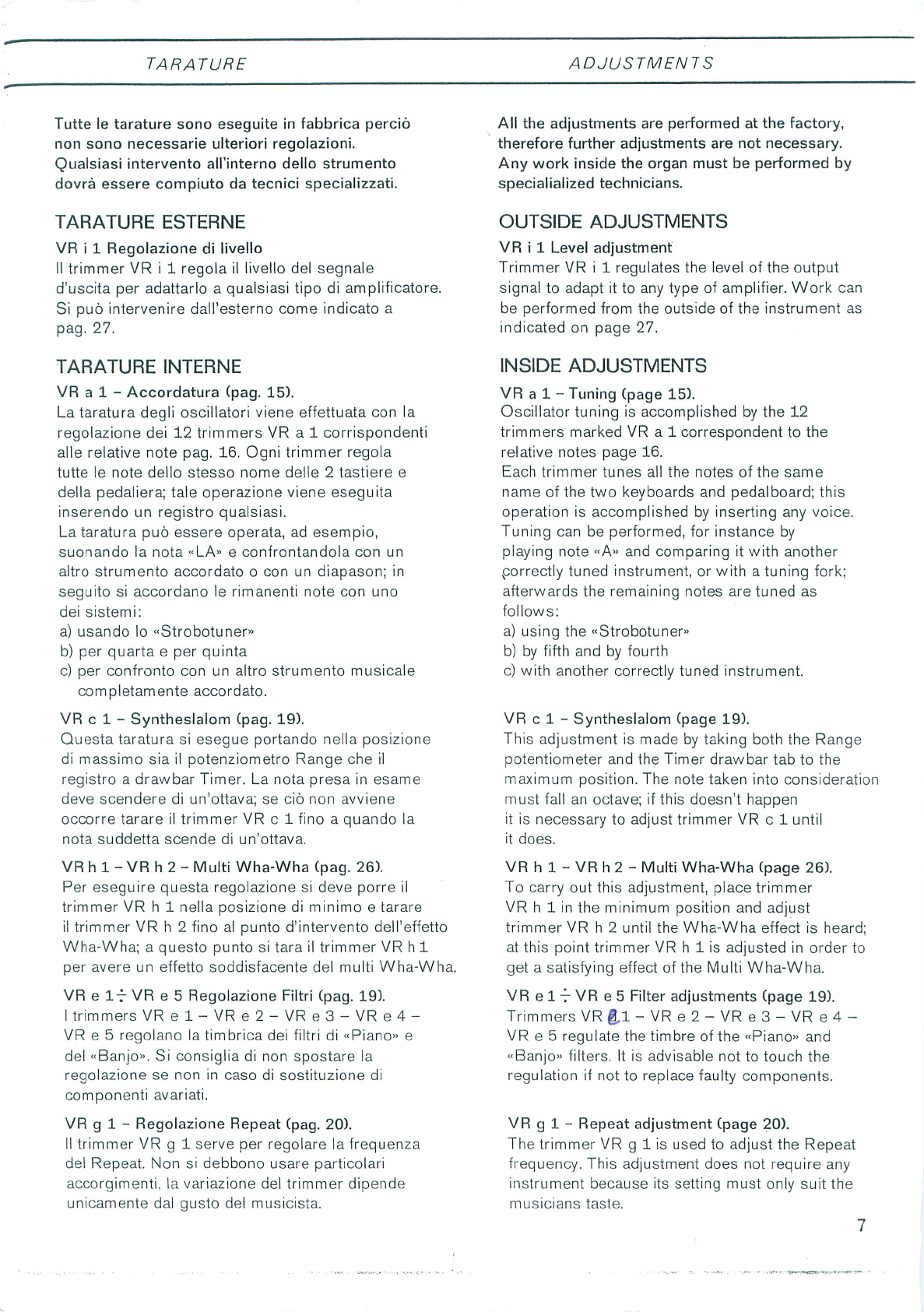
TARATURE
ESTERNE
VR
i
1
Regolazione
di
livello
II
trimmer
VR
i
1
regola
il
livello
del
segnale
d'uscita
per
adattarlo
a
qualsiasi
tipo
di
amplificatore.
Si
puo
intervenire
dall'esterno
come
indicato
a
pag.
27.
TARATURE
INTERNE
VR
a
1 -
Accordatura
(pag.
15).
Lataratura
degli
oscillatori
viene
effettuata
con
la
regolazione
dei
12
trimmers
VR
a
1
corrispondenti
alle
relative
note
pag.
16.
Ogni
trimmer
regola
tutte
le
note
dello
stesso
nome
delle
2
tastiere
e
della
pedaliera;
tale
operazione
viene eseguita
inserendo
un
registro
qualsiasi.
La
taratura
puo
essere
operata,
ad
esempio,
suonando
la
nota
«LA»
e
confrontandola
con
un
altro
strumento
accordato
o
con
un
diapason;
in
seguito
si
accordano
le
rimanenti
note
con
uno
dei
sistemi:
a)
usando
lo
«Strobotuner»
b)
per
quarta
e
per
quinta
c)
per
confronto
con
un
altro
strumento
musicale
completamente
accordato.
VR
c
1 -
Syntheslalom
(pag.
19).
Questa
taratura
si
esegue
portando
nella
posizione
di
massimo
sia
il
potenziometro
Range
che
il
registro
a
drawbar
Timer.
La
nota
presa
in
esame
deve
scendere
di
un'ottava;
se
cio
non
avviene
occorre
tarare
il
trimmer
VR
c
1
fino
a
quando
la
nota
suddetta
scende
di
un'ottava.
VR
h
1 -
VR
h
2
-
Multi
Wha-Wha
(pag.
26).
Per
eseguire
questa
regolazione
si
deve
porre
il
trimmer
VR
h
1
nella
posizione
di
minimo
e
tarare
il
trimmer
VR
h
2
fino
al
punto
d'intervento
dell'effetto
Wha-Wha;
a
questo
punto
si
tara
il
trimmer
VR
h
1
per
avere
un
effetto
soddisfacente
del
multi
Wha-Wha.
VR
e
It
VR
e 5
Regolazione
Filtri
(pag.
19).
I
trimmers
VRel-VRe2-VRe3-VRe4-
VR
e
5
regolano
la
timbrica
dei
filtri
di
«Piano»
e
del
«Banjo».
Si
consiglia
di
non
spostare
la
regolazione
se
non
in
caso
di
sostituzione
di
componenti
avariati.
VR
g
1
-
Regolazione
Repeat
(pag.
20).
II
trimmer
VR
g 1
serve
per
regolare
la
frequenza
del
Repeat.
Non
si
debbono
usare
particolari
accorgimenti,
la
variazione
del
trimmer dipende
unicamente
dal
gusto
del
musicista.
All
the
adjustments
are
performed
at
the
factory,
therefore
further
adjustments
are
not
necessary.
Any
work
inside
the
organ
must
be
performed
by
specialialized
technicians.
OUTSIDE
ADJUSTMENTS
VR
i
1
Level
adjustment
Trimmer
VR
i
1
regulates the
level of
the
output
signal
to
adapt
it
to
any
type
of
amplifier.
Work
can
be
performed
from
the
outside
of
the
instrument
as
indicated
on
page
27.
INSIDE
ADJUSTMENTS
VR
a 1
-
Tuning
(page
15).
Oscillator
tuning
is
accomplished
by
the
12
trimmers
marked
VR
a
1
correspondent
to
the
relative
notes
page
16.
Each
trimmer
tunes
all
the
notes
of
the
same
name
of
the
two
keyboards
and
pedalboard;
this
operation
is
accomplished
by
inserting
any
voice.
Tuning
can
be
performed,
for
instance
by
playing
note
«A»
and
comparing
it
with
another
porrectly
tuned
instrument,
or
with
a
tuning
fork;
afterwards
the
remaining
notes
are
tuned
as
follows:
a)
using
the
«Strobotuner»
b)
by
fifth
and
by
fourth
c)
with
another
correctly
tuned
instrument.
VR
c 1
-
Syntheslalom
(page
19).
This
adjustment
is
made
by
taking
both
the
Range
potentiometer
and
the
Timer
drawbar
tab
to
the
maximum
position.
The
note
taken
into
consideration
must
fall
an
octave;
if
this
doesn't
happen
it
is
necessary
to
adjust
trimmer
VR
c
1
until
it
does.
VR
h 1 -
VR
h
2 -
Multi
Wha-Wha
(page
26).
To
carry
out
this
adjustment,
place
trimmer
VR
h
1
in
the
minimum
position
and
adjust
trimmer
VR
h
2
until
the
Wha-Wha
effect
is
heard;
at
this
point
trimmer
VR
h
1
is
adjusted
in
order
to
get
a
satisfying
effect
of
the
Multi
Wha-Wha.
VR
e
1
t
VR
e
5
Filter
adjustments
(page
19).
Trimmers
VR
&1
-
VR
e
2
-
VR
e
3
-
VR
e
4
-
VR
e
5
regulate
the
timbre
of
the
«Piano»
and
«Banjo»
filters.
It
is
advisable
not
to
touch
the
regulation
if
not
to
replace
faulty
components.
VR
g 1
-
Repeat
adjustment
(page
20).
The
trimmer
VR
g
1
is
used
to
adjust
the
Repeat
frequency.
This
adjustment
does
not
require
any
instrument
because
its
setting
must
only
suit
the
musicians
taste.
Scan by Manual Manor
http://www.markglinsky.com/ManualManor.html
RICERCA
GUASTI
TROUBLESHOOTING
GUIDE
Qualora
lo
strumento
non
dovesse
funzionare
verificare
quanto
segue:
-
che
lo
strumento
sia
acceso
-
che
il
pedale
d'espressione
sia
al
massimo
-
che
non
sia
inserito
un
jack
nella
presa
cuffia
(pag.
27).
-
che
i
fusibili
dell'alimentatore
non
siano
bruciati
(la
lampada
spia
resta
accesa
anche
quando
il
fusibile
si
e
bruciato).
Se
le
suddette
verifiche
non
danno
risultato,
aprire
lo
strumento
e
controllare
che
non
ci
siano
corpi
estranei,
connettori
staccati,
fili
o
cavi
rotti,
fusibili
interrotti,
o
addirittura
circuiti
stampati
rotti.
A
-
Se
lo
strumento
fosse
completamente
muto,
verificare
innanzitutto
le
tensioni
e
i
collegamenti
interni
e
d'uscita
dell'alimentatore
(DWG
13).
Tutti
i
valori
delle
tensioni
sono
riportati
sullo
schema
elettrico
e
tale
misura
va
effettuata
con
un
voltometro
di
almeno
20.000
ohm/V.
In
particolare
controllare
i
transistosi
Q
2
-
Q
1
e
i
diodi
D
1,
D
2,
Z
1
e
Z
2
del
circuito
dell'alimen
tatore.
Successivamente
controllare
i
transistori
Q
d
7
e
Q
d
8
del
circuito
funzionante
da
preamplificatore
d'uscita
(pag.
22).
B
-
Se
non
funzionasse
un
gruppo
o
un
effetto
(Vibrato,
Wha-Wha,
Tastiera
ecc.
ecc.)
prima
di
procedere
accertarsi
sempre
che
non
ci
siano
fili
staccati
o
circuiti
stampati
rotti.
Riferendosi
sempre
allo
schema
controllare
le
tensioni
delle
rispettive
piastre.
Sul
lato
rame
dei
circuiti
stampati
sono
riportati
i
numeri
di
identificazione
PA
che
permettono
di
ritrovare
sullo
schema
elettrico
il
circuito
interessato.
Se
non
funzionasse
uno
dei
seguenti
effetti
occorre
controllare
ed
eventualmente
sostituire
i
transistori
interessati.
If
the
instrument
is
not
working
check:
-
that
the
instrument
is
switched
on
-
that
the
swell pedal
is
fully
home
-
that
a
plug
is
not
inserted
in
the
headphone
jack
(page
27).
-
that
the
fuses
of
the
power
supply
are
not
burnt
(the
pilot
light
remains
on
even
when
the
fuse
burns
out).
If
the
above
checks
are
resultless,
open
the
instru
ment
and
see
that
there
are
no
foreign
bodies
in
it,
disconnected
plugs,
broken
wires
or
broken
cables,
burnt
fuses,
or
cracked
printed
circuits.
A
-
If
the
instrument
is
completely
dead,
check
the
voltages
and
internal
connections
and
output
connections
of
the
power
amplifier
(DWG
13).
All
the
voltage
values
are
indicated
on
the
schematic
diagram
and
the
measurement
is
accomplished
with
a voltmeter
of
at
least
20.000
ohm/V.
In
particular
check
transistors
Q
1-
Q
2
and
diodes
D
1,
D
2,
Z
1
and
Z
2
of
the
supply
circuit.
Following
this,check
transistors
Q
d
7
and
Q
d
8
on
the
circuit
acting
as
output
preamplifier
(page
22
B
-
If
an
assembly
board
or
an
effect
(Vibrato,
Wha-Wha,
Keyboard
etc.
etc.)
is
not
working
before
proceeding
always
make
sure
that
there
aren't
any
broken
wires
or
cracked
printed
boards.
Always
refer
to
the
schematic
diagram
and
check
the
voltages
of
the
respective
boards.
Identification
numbers
such
as
PA
are
printed
on
the
copper
side
of
the
boards
thus
facilitating
finding
the
relative
circuit
on
the
diagram.
If
one
of
the
following
effects
are
not
working,
it
is
necessary
to
check
and
eventually
replace
the
relative
transistors.
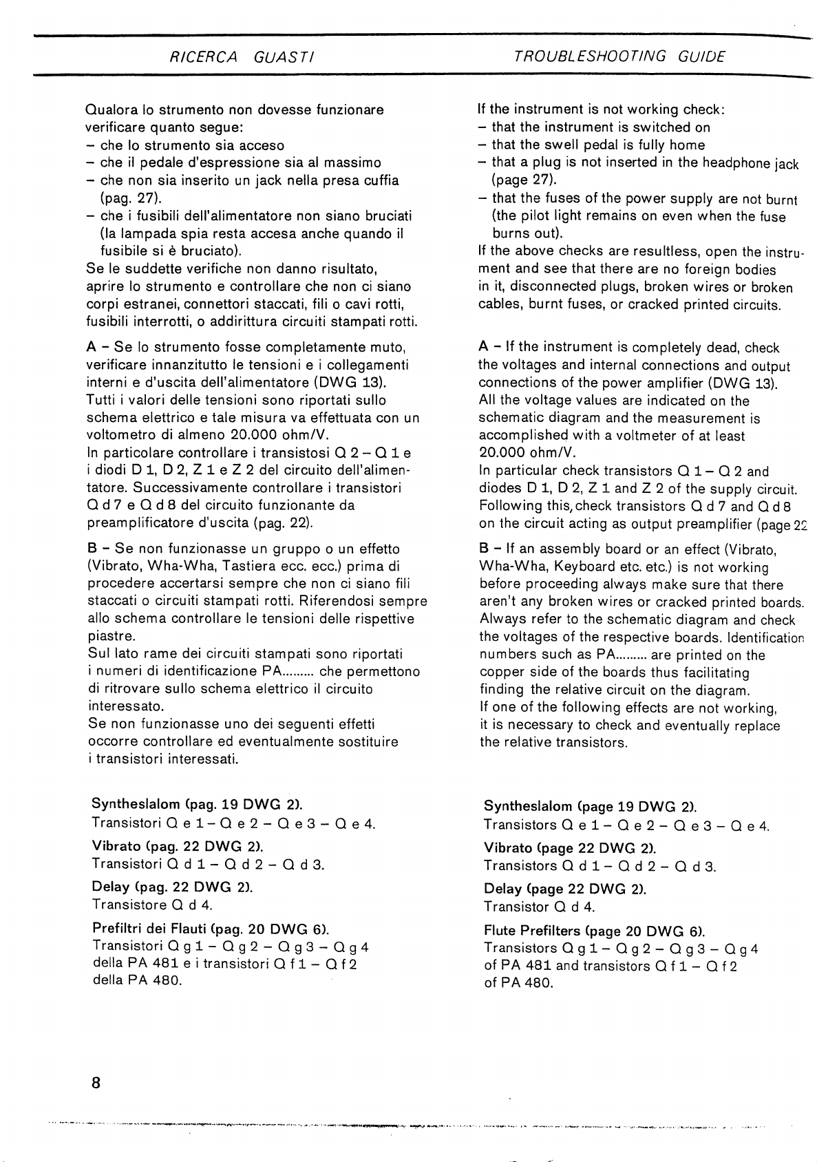
Syntheslalom
(pag.
19
DWG
2).
Transistori
Qel-Qe2-Qe3-Qe4.
Vibrato
(pag.
22
DWG
2).
Transistori
Q
d
1
-
Q
d
2
-
Q
d
3.
Delay
(pag.
22
DWG
2).
Transistore
Q
d
4.
Prefiltri
dei
Flauti
(pag.
20
DWG
6).
Transistori
Qgl-Qg2-Qg3-Qg4
della
PA
481
e
i
transistori
Q
f
1
-
Q
f
2
della
PA
480.
Syntheslalom
(page
19
DWG
2).
Transistors
Qel-Qe2-Qe3-Qe4.
Vibrato
(page
22
DWG
2).
Transistors
Q
d 1
-
Q
d
2
-
Q
d
3.
Delay
(page
22
DWG
2).
Transistor
Q
d
4.
Flute
Prefilters
(page
20
DWG
6).
Transistors
Qgl-Qg2-Qg3-Qg4
of
PA
481
and
transistors
Q
f
1
-
Q
f
2
of
PA
480.
8
Scan by Manual Manor
http://www.markglinsky.com/ManualManor.html
RICERCA
GUASTI
TROUBLESHOOTING
GUIDE
Preamplificatore
dei
Filtri
dei
Flauti
(pag.
20
DWG
7).
Transistore
Q
f
3.
Preamplificatore
dei
Filtri
Sharp
(pag.
20
DWG
7).
Transistori
Q
f
4
-
Q
f
5.
Filtri
della
Percussione
(pag.
20
DWG
8).
ContrQllare
il
preamplificatore,
cioe
i
transistori
Q
g
5
-
Q
g
6,
il
transistore
Keyer
Q
g
10
e
il
diodo
D
g
2.
Controllare
inoltre
il
transistore
pilota
Q
g 7
e
il
multivibratore
costituito
dai
due
transistori
Q
g
9
-
Q
g
8.
Modulo
di
Decadimento
(pag.
27
DWG
9).
Transistore
Q
b 1 e
i
diodi
Dbl-Db2-
D
b
3
-
D
b
4.
Filtri
Bassi
del
manuale
inferiore
(pag.
19
DWG
10).
Controllare
i
transistori
funzionanti
da
preamplifica-
tori
Q
e
1
-
Q
e 2
successivamente
i
transistori
dei
vari
effetti,
«HonkieTonk
-
Harpsichord
-
Horn»
transistore
Q
e
4,
«Piano»
transistore
Q
e
5.
Filtri
Acuti
del
manuale
inferiore
(pag.
19
DWG
10).
Controllare
i
transistori
funzionanti
da
preamplifi
catore
Q
e
10
-
Qell-Qe
12,
successivamente
i
transistori
relativi
ai
filtri:
«Piano»
transistori
Q
e
6
-
Q
e
7.
«Banjo»
transistore
Q
e
8.
«Honkie
Tonk»
transistore
Q
e
9.
Preamplificatore
Generale
del
manuale
inferiore
(pag.
22
DWG
12).
Prima
di
procedere
al
controllo
dei
Filtri
Bassi
e
Acuti
del
manuale
inferiore
controllare
i
transistori
funzionanti
da
preamplificatore
Q
d
5
-
Q
d
6.
Effetto
Wha-Wha
(pag.
26
DWG
12).
Innanzitutto
controllare
i
transistori
pilota
Q
h
2
-
Qh3-Qh4-Qh5-Qh6,
e
il
transistore
oscillatore
Q
h
1
successivamente
controllare
i
transistori
Qh7-Qh8-Qh9.
C
-
Se
non
funzionassero
una
o
piu
note
controllare
che
le
molle
dei
tasti
corrispondenti
siano
al
loro
posto
e
che
non
siano
interrotti
i
fili
o
le
tracce
del
circuito
stampato
della
contattiera.
Fatto
questo
possono
verificarsi
due
casi:
1)
se
dopo
aver
inserito
il
piede
piu
acuto
(registro
Flute
21)
non
funziona
la
stessa
nota
su
piu
Preamplifier
of
the
Flute
Filters
(page
20
DWG
7).
Transistor
Q
f
3.
Preamplifier
of
the
Sharp
Filters
(page
20
DWG
7).
Transistors
Q
f
4
-
Q
f
5.
Percussion
Filters
(page
20
DWG
8).
Check
the
preamplifier,
that
is,
transistors
Q
g
5
-
Q
g
6,
the
Keyer
Q
g
10
transistor
and
diode
D
g
2.
Furthermore
check
the
driver
transistor
Q
g
7
and
the
multivibrator
made
up
of
two
transistors
Q
g
8
-
Q
g
9.
Decay
Modulator
(page
27
DWG
9).
Transistor
Q
b
1
and
diodes
Dbl-
D
b
2
-
D
b
3
-
D
b
4.
Lower
manual
Bass
Filters
(page
19
DWG
10).
Check
the
transistors
acting
as
preamplifiers,
Q
e
1
-
Q
e
2,
then
the
transistors
of
the
various
effects,
«HonkieTonk
-
Harpsichord
-
Horn»
transistor
Q
e
4,
«Piano»
transistor
Q
e
5.
Lower
manual
Sharp
Filters
(page
19
DWG
10).
Check
transistors
Q
e
10
-
Q
e
11
-
Q
e
12
acting
as
preamplifier,
then
the
transistors
relative
to
the
following
filters:
«Piano»
transistors
Q
e
6
-
Q
e
7.
«Banjo»
transistor
Q
e
8.
«Honkie
Tonk»
transistor
Q
e
9.
Lower
manual
General
Preamplifier
(page
22
DWG
12).
Before
proceeding
in
checking
the
lower
manual
Bass
and
Sharp
Filters,
check
the
following
transistors
acting
as
preamplifier,
Q
d
5
-
Q
d
6.
Wha-Wha
effect
(page
26
DWG
12).
First
of
all
check
the
driver
transistors
Q
h
2
-
Qh3-Qh4-Qh5-Qh6andthe
oscillator
transistor
Q
h
1
then
check
transistors
Q
h
7
-
Q
h
8
-
Q
h
9.
C
-
If
one
or
more
notes
are
not
working,
check
that
the
springs
of
the
relative
keys
are
in
the
proper
setting
and
that
there
are
no
broken
leads
or
open
conductor
paths
on
the
printed
circuit
of
the
switchboard.
Done
this
two
possibilities
must
be
considered:
1)
if
after
having
switched
the
highest
treble
Scan by Manual Manor
http://www.markglinsky.com/ManualManor.html

RICERCA
GUASTI
TROUBLESHOOTING
GUIDE
'
ottave,
ad
esempio
non
funzionano
tutti
i
DO,
si
deve
intervenire sulPoscillatore
principale
(pag.
00
PA
357/2)
controllando
che
all'uscita
relativa
alia
nota
presa
in
esame
sia
presente
un
segnale
ad
onda
quadra
di
circa
10
Vpp;
in
caso
contrario
sostituire
i
transistori
Qal-Qa2-Qa3del
multivibratore.
2)
Se
invece
(sempre
usando
il
piede
acuto
2')
non
funziona
una
o
piu
note,
non
comprese
per6
nelPultima
ottava
(Oscillators
DWG
4)
allora
il
guasto
dipende
dai
divisori
integrati.
Facendo
riferimento
al
DWG
3
verificare
la
tensione
tra
i
terminali
1-
8
e
tra
14
-
8
dei
circuit!
integrati;
se
le
tensioni
non
sono
quelle
indicate
sullo
schema
controllare
i
collegamenti
di
alimentazione.
II
divisore
integrato
comprende
7
stadi
cosi
suddivisi:
-
3
divisori
in
cascata
con
ingresso
al
piedino
2
ed
uscita
ai
piedini
3,
4,
5.
-
2
divisori
in
cascata
con
ingresso
al
piedino
13
ed
uscita
al
piedini
12, 11.
-
1
divisore
con
ingresso
al
piedino
10
ed
uscita
al
piedino
9.
-
1
divisore
con
ingresso
al
piedino
6
ed
uscita
al
piedino
7.
Poniamo,
ad
esempio,
che
non
funzioni
il
terzo
«DO»
(partendo
da
destra)
del
manuale
superiore
(sempre
usando
il
registro
Flute
2').
Dopo
aver
verificato
la
perfetta
funzionalita
delle
molle
e
dei
collegamenti,
controllare
con
un
oscilloscopio
se
al
piedino
4
delM.C.(3)(come
indicato
sulla
tabella
di
riferimento)
esce
il
segnale
ad
onda
quadra
di
almeno
10
Vpp;
se
esce
il
segnale,
il
guasto
e
tra
il
circuito
integrato
e
il
tasto,
altrimenti
si
deve
vedere
se
il
segnale
e
presente
all'entrata
del
divisore
integrato
(nel
nostro
caso
piedino
2);
se
c'e
segnale,
il
guasto
dipende
dal
circuito
integrato
che
deve
essere
sostituito;
se
non
c'e,
il
guasto
e
da
ricercarsi
sulla
contattiera.
N.B.
-
Dovendo
sostituire
I'l.C.
occorre
prestare
attenzione
affinche
il
nuovo
I.C.
venga
montato
nella
posizione
corretta.
Ricordare
che
il
piedino
n.loe
contras-
segnato
da
un
puntino
o
e
situato
sotto
una
tacchetta
a
forma
di
mezzaluna
(vedere
(vedere
DWG
3).
footage
on
(tab
Flute
2')
the
same
note
doesn't
work
on
more
than
an
octave
for
example
all
the
C's,
work
must
be
performed
on
the
main
oscillator
(page
00
PA
357/2),
by
checking
that
a
square
wave
signal
of
approx.
10
Vpp
is
present
at
the
output
of
the
note
taken
into
•
consideration;
if
this
doesn't
happen
replace
transistors
Qal-Qa2-Qa3ofthe
multivibrator.
2)
If
however,
(always
using
the
highest
treble
footage
2')
one
or
more
notes
do
not
work,
which
aren't
included
in
the
last
octave
(Oscillators
DWG
4)
then
the
fault
depends
on
the
integrated
dividers.
Referring
to
DWG
3
check
the
voltage
between
pin
1-8
and
14
-
8,
of
the
integrated
circuits;
if
the
voltages
aren't
those
indicated
on
the
schematic,
check
the
supply
connections.
The
integrated
divider
includes
7
stages
divided
as
follows:
-
3
chain
dividers
with
input
at
pin
2
and
outputs
at
pin
3,
4, 5.
-
2
chain
dividers
with
input
at
pin
13
and
outputs
at
pin
12, 11.
-
1
divider
with
input
at
pin
10
and
output
at
pin
9.
-
1
divider
with
input
at
pin
6
and
output
at
pin
7.
Let
us
suppose
that,
always
using
Flute
2'
tab,
the
third
«C»
from
the
right
of
the
upper
manual
is
not
working.
After
having
checked
the
proper
order
of
the
springs
and
the
connections,
check
with
an
oscilloscope,
if
a
square
wave
signal
of
at
least
10
Vpp
comes
out
of
pin
4
of
I.C.(3)(as
shown
on
the
reference
table);
if
the
output
signal
is
present
the
fault
is
located
between
the
I.C.
and
the
key;
if
the
output
signal
is
missing,
it
is
necessary
to
check
the
input
side
of
the
divider
I.C.
(in
our
case
pin
2).
The
presence
of
the
signal
at
the
input
indicates
that
the
I.C.
must
be
replaced;
the
absence
of
signal
at
the
same
input
indicates
that
the
fault
is
located
on
the
switchboard.
N.B.
-
When
replacing
the
I.C.
care
must
be
taken
in
locating
the
new
I.C.
into
the
correct
position.
Remember
that
pin
n.
1
is
marked
with
a
dot
or
the
pin
itself
is
situated
under
an
index
point
(see
DWG
3).
10
Scan by Manual Manor
http://www.markglinsky.com/ManualManor.html
COME
A
PRIRE
LO
STRUM
ENTO
HOW
TO
OPEN
THE
INSTRUMENT
Qualsiasi
intervento
all'interno
dello
strumento
dovra
essere
compiuto
da
tecnici
specializzati.
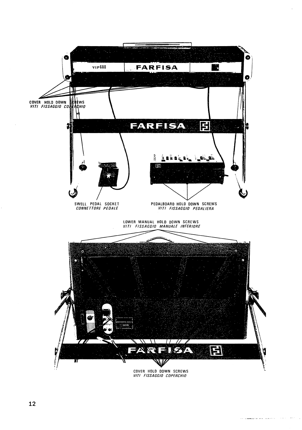
1)
Per
togliere
il
coperchio
agire
come
segue:
svitare
le
viti
indicate
a
pag.
12.;
sollevare
il
coperchio
dalla
parte
posteriore
e
tirare
lentamente;
staccare
il
filo
di
massa
dal
coperchio
e
ricordarsi
di
ricollegare
lo
stesso
filo
quando
si
chiude
lo
strumento
(se
non
si
ricollega
il
filo
di
massa
si
potrebbero
avere
ronzii
fastidiosi).
Fatto
questo
si
puo
intervenire
sulle
seguenti
parti:
PA
479
Filtri
manuale
inferiore
(pag.
19)
PA
478
Syntheslalom
(pag.
19)
PA
480
Filtri
«Flauti
-
Sharps»
(pag.
20)
PA
481
Percussion
-
Repeat
(pag.
20)
PA
357-2
Oscillatori
(pag.
15)
PA
486
Wha-Wha
(pag.
26).
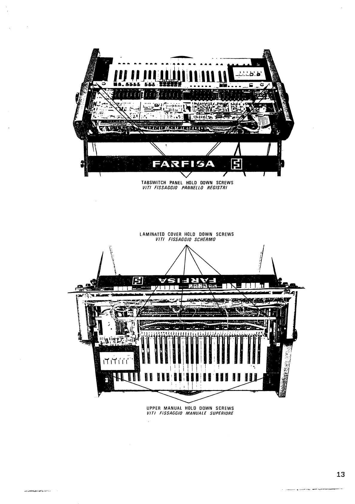
2)
Sollevando
il
pannello
dei
registri
si
puo
intervenire:
lato
rame
delle
PA
479
-
PA
478
-
PA
480
-
PA
481
(pag.
13).
Potenziometri
(pag.
21).
Inoltre
togliendo
lo
schermo
(vedere
pag.
13)
si
puo
intervenire
sulla
contattiera
PA
476-1.
3)
Sollevando
il
manuale
superiore
si
puo
intervenire
sulle
seguenti
parti:
Tastiera
del
manuale
superiore
(pag.
23).
Base
porta
prese
(pag-
24).
Alimentatore
(pag.
25).
4)
Sollevando
il
manuale
inferiore
si
puo
intervenire
sulla
contattiera
del
manuale
inferiore
PA
485
dove
sono
montati
i
modulini
di
dinamica
PA
324
-
PA
324-1
-
PA
324-2
-
PA
324-3
-
PA
324-4.
Inoltre
si
pu6
intervenire
sulle
molle
e
contatti
della
tastiera.
5)
Per
intervenire
sulla
contattiera
del
manuale
inferiore
PA
485
e
piastrini
PA
324
-
PA
324-1,
PA
324-2,
PA
324-3,
PA
324-4
e
sufficiente
rovesciare
lo
strumento
e
sfilare
le
viti
indicate
a
pag.
12
(vedere
illustrazione
a
pag.
27).
Any
work
inside
the
organ
must
be
performed
by
specialised
technicians.
1)
Remove
the
lid
as
follows:
unscrew
the
screws
indicated
on
page
12;
lift
the
lid
from
the
rear
and
pull
slowly;
disconnect
the
ground
wire
from
the
lid
and
remember
to
reconnect
it
when
closing
the
instrument
(if
it
is
not
reconnected
an
annoying
humming
may
be
heard).
After
having
opened
the
instrument
work
may
be
performed
on
the
following
parts:
PA
479
Lower
manual
filters
(page
19)
PA
478
Syntheslalom
(page
19)
PA
480
«Flutes
-
Sharps»
filters
(page
20)
PA
481
Percussion
-
Repeat
(page
20)
PA
357-2
Oscillator
(page
15)
PA
486
Wha-Wha
(page
26).
2)
On
lifting
the
voice
register
panel
work
may
be
performed
on:
the
copper
side
of
PA
479
-
PA
478
-
PA
480
-
PA
481
(page
13).
Potentiometer
(page
21).
Furthermore
by
removing
the
screen
(see
page
13)
work
may
be
performed
on
the
contactboard
PA
476-1.
3)
By
lifting
the
upper
manual
work
may
be
performed
on
the following
parts:
Upper
manual
keyboard
(page
23).
Base
with
sockets
(page
24).
Power
Supply
(page
25).
4)
By
lifting
the
lower
manual
work
may
be
performed
on
the
lower
manual
contactboard
PA
485
where
the
dynamic
modules
are
assembled
PA
324
-
PA
324-1
-
PA
324-2
-
PA
324-3
-
PA
324-4.
Furthermore
work
may
be
performed
on
the
keyboard
springs
and
contacts.
5)
To
be
able
to
work
on
the
lower
manual
contactboard
PA
485
and on
boards
PA
324,
PA
324-1,
PA
324-2,
PA
324-3,
PA
324-4
just
turn
the
instrument
upside
down
and
unscrew
the
screws
indicated
on
page
12.
(See
illustration
on
page
27).
11
Scan by Manual Manor
http://www.markglinsky.com/ManualManor.html
COVER
HOLD
DOWN
VITI
FISSAGGIO
CO
SWELL
PEDAL
SOCKET
CONNETTORE
PEDA
IE
PEDALBOARD
HOLD
DOWN
SCREWS
VITI
FISSAGGIO
PEDAL
I
ERA
LOWER
MANUAL
HOLD
DOWN
SCREWS
VITI
FISSAGGIO
MANUALE
INFER
I
ORE
COVER
HOLD
DOWN
SCREWS
VITI
FISSAGGIO
COPERCHIO
12
Scan by Manual Manor
http://www.markglinsky.com/ManualManor.html
TABSWITCH
PANEL
HOLD
DOWN
SCREWS
VITI
FISSAGGIO
PANNELLO
REG
1STRI
LAMINATED
COVER
HOLD
DOWN
SCREWS
VITI
FISSAGGIO
SCHERMO
\
UPPER
MANUAL
HOLD
DOWN
SCREWS
VITI
FISSAGGIO
MANUALE
SUPERIORE
13
Scan by Manual Manor
http://www.markglinsky.com/ManualManor.html
14
Scan by Manual Manor
http://www.markglinsky.com/ManualManor.html

PA
357-2
PA
486
CM
15
Scan by Manual Manor
http://www.markglinsky.com/ManualManor.html

OSCILLATOR
BOARD
(PA 357-2)
MVBTR
TRANSISTOR
Qo
2
DIODE
Da
2
BUFFER
TRANSISTOR
Qa
3
MVBTR
TRANSISTOR
Qa
1
OSCILLATORS
OUTPUT
DIODE
Da
1
VRai
TUNING
A
=
LA
VRal
TUNING
D
=
RE
VRai
TUNING
G
=
SOL
VRal
TUNING
C
=
DO
VRal
TUNING
F
=
FA
VRal
TUNING
A=
LA
8
8
VRal
TUNING
D
=
RE
8 8
VRal
TUNING
G
=SOL
8
8
VRal
TUNING
C
=
DO
8
8
VRal
TUNING
F
=
FA
VRal
TUNING
B
=
SI
VRal
TUNING
E
=
Ml
16
Scan by Manual Manor
http://www.markglinsky.com/ManualManor.html
17
Scan by Manual Manor
http://www.markglinsky.com/ManualManor.html
18
Scan by Manual Manor
http://www.markglinsky.com/ManualManor.html
PA
479
Qc1
GROUND
Qe2
terra
Qe3
VRe1
Ce29
Qe4
Qc2
Ce64
Qe9
Qe7
VRd
Qc4
Qe1
VRe2
Qe5
Qe8
Qe6
VRe3
VRe5
Qe10
Qe11
Qe12
VRe4
19
Scan by Manual Manor
http://www.markglinsky.com/ManualManor.html
Other Farfisa Musical Instrument manuals


