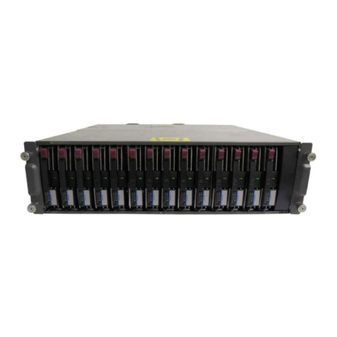
Fastora DAS-315SA User manual

FASTORA DAS-315SA Disk Array
FASTORA
DAS-315SA Disk Array
User Guide
V. 1.02a

FASTORA DAS-315SA Disk Array
2
The information in this guide may be changed without notice. We assume no
responsibility for any errors which may appear in this guide. The FASTORA
DAS-315SA is a trademark of FASTORA. Microsoft, Windows and Windows
logo are trademarks of Microsoft Corporation.
Copyright 2004. All rights reserved. No Part of the contents in this guide may
be transmitted or reproduced in any form or by any means without the written
permission of the manufacturer. Printed in Taiwan.
The revision date for this guide is May 26, 2004
Version 1.02
FCC Statement
This equipment has been tested and found to comply with the limits for a Class
A digital device, pursuant to Part 15 of the FCC Rules. These limits are
designed to provide reasonable protection against harmful interference in a
residential installation.
This equipment generates and can radiate radio frequency energy and, if not
installed and used according to the instructions, may cause harmful
interference to radio communications. However, there is no guarantee that
interference will not occur in a particular installation. If this equipment does
cause harmful interference to radio or television reception, which is found by
turning the equipment off and on, the user is encouraged to try to correct the
interference by one or more of the following measures:
--Reorient or relocate the receiving antenna
--Increase the separation between the equipment and device
--Connect the equipment to an outlet other than the receiver
--Consult a dealer or an experienced radio/TV technician for assistance
CE Mark Warning
This is a Class A product. In a domestic environment, this product may cause
radio interference in which case the user may be required to take adequate
measures.

FASTORA DAS-315SA Disk Array
3
Chapter 1 General Information
This chapter provides general information of the FASTORA DAS-315SA.
The following topics are covered in this chapter:
◆ Introduction
◆ Key Features & Benefits
◆ Unpacking Your DAS-315SA
◆ Components of DAS-315SA
1.1 Introduction
FASTORADAS-315 Series is the leading Ultra320-to-Serial ATA external DAS
subsystem. It supports not only RAID level 0, 1, 3, 5,10, but also RAID level 6
which increases the data reliability dramatically. Acompact 3U design built with
15 drive trays for 3.5" disk drive with 1" height provides a very large capacity or
flexible configuration as users' demand.
The unique and excellent heat dissipation design makes the subsystem more
reliable and available. An easy and user friendly GUI guides users to manage
the subsystem through standard Ethernet quickly.
Throughout this manual, the FASTORA DAS-315SA may be referred to as
DAS-315SA,or simply as DAS.

FASTORA DAS-315SA Disk Array
4
1.2 Key Features and Benefits
Supports 0, 1, 3, 5, 10, and JBOD, ensuring a full data protection.
Provides 15 disk bays, fulfilling your business demand for data
storage.
Hot-swappable design guarantees nonstop operation.
2 Ultra320 SCSI channels provide high-speed data transmission.
15 driver bays for 3.5” disk drive
Up to 1GB cache memory
3U compact tower design for more capacity
Cable-less design for better reliability
Swappable design for faster and easier maintenance
User-friendly configuration via RS-232 port or Ethernet
1.3 Unpacking Your FASTORA DAS-315SA
Before removing your FASTORADAS-315SA from the shipping carton, you
should thoroughly inspect the physical condition of the container. The package
of FASTORADAS-315SA should appear in good condition when you receive it.
If any damaged found, do not remove the components. Contact the place of
purchase for further instructions.
If the shipping container appears to be in good condition, unpack it and verify
that the FASTORADAS-315SA and accessories are all there and in good
condition.

FASTORA DAS-315SA Disk Array
5
Your FASTORADAS-315SA package should contain the following items:
If an item is missing or damaged, please contact the place of purchase for
assistance. Retain the shipping container and packing material for reuse.
Before you begin to use your FASTORADAS-315SA, read
section 1.4 Components of the FASTORA DAS-315SA to learn
more about the major components or your DAS system.
Items Quantity
FASTORA DAS-315SA unit 1
Drive Canister 15
Accessory Box
Ultra 320 SCSI Cable 1
Power Cord 2
RS-232 Cable 1
Spare screws 40
Ultra 320 Terminator 1
User Menu CD 1
Rack-mount Kit (option)
Note

FASTORA DAS-315SA Disk Array
6
1.4 Components of the FASTORA DAS-315SA
This section describes the major components of the FASTORA DAS-315SA,
including its front panel, LED display panel and rear panel. Read this section
before you start to use your RAID DAS Subsystem.
1.4.1 The Front Panel
The front panel of FASTORA DAS-315SA is shown below.
Figure 1-1
For the specific detail information on each drive canister, please refer to Figure
1-2, and Table 1-1 for explanation. For LED status, please refer to Table 1-2.
Figure 1-2

FASTORA DAS-315SA Disk Array
7
Table 1-1
Items Descriptions
Drive handle Used to lock and fix the drive canisters
Drive lock Used to lock or release the drive canisters
Drive number Used to indicate the number of each canister.
(1-15)
LED1 (Red) Used to indicate the hard drive status
LED2 (Green) Used to indicate the hard drive status.
Table 1-2
LED Indication Status
LED 1 (Red) continuous flash No hard drive inserted or hard
drive failed
LED 2 (Green) blinking Hard drive access (read/write)
No flashing nor blinking on both
LEDs System standby
Both LED 1 LED 2 continuous flash System rebuilding
Please note that DAS-315SA does not have a power button. When power
cords are unplugged, you need to wait at least 5 seconds so that you can
power on DAS-315SA again. This is designed for safe and better operation
and performance, please note with extra care.

FASTORA DAS-315SA Disk Array
8
1.4.2 The Rear Panel
The rear panel of FASTORADAS-315SA is shown below. Refer to Table 1-3
for detailed description of each part on the rear panel of DAS-315SA.
Figure 1-3
Table 1-3
Part Description
Con 1 port
This is a RS-232 serial port, allowing you to connect to a
terminal or a PC. You may configure this DAS, and upgrade the
firmware and RAID.
Con 2 port
(Debug Model) This is a RS-232 serial port, allowing you to connect to a
terminal or a PC. This port is designed for debug.
LAN Web browser RAID management through standard 10/100
Ethernet port
Host 1
Host 2
FASTORADAS-315SA has two host channels— Host 1 and
Host2 —to allow you to connect to SCSI devices.
System Fans There are 2 fans located at the rear of the system unit. They are
designed to provide good airflow and heat dissipation.
Power
Supplies &
Fans
The DAS comes with 2 hot-swappable power supplies located
at the rear of the subsystem. If the power supplies are in use
and one fails to function, an audible alarm will warn you of the
power failure.

FASTORA DAS-315SA Disk Array
9
Chapter 2 Hardware Installation
This chapter discusses the basic operational installation and the Disk Drive
installation.
The following topics are covered in this chapter:
Preparing for the Installation
Disk Drive Installation
Table and Shelf Installation
Rack-Mount Installation
2.1 Preparing for the Installation
If you want to connect your FASTORADAS-315SA DAS to the computer using
a SCSI adapter, install the adapter(s) in an available slot in the computer prior
to beginning FASTORADAS-315SA installation. See your operating system
manuals for the configuration procedures for the host bus adapter.
2.1.1 Terminating Disk Drive Channels
All SCSI buses must be terminated at each end. Termination absorbs electrical
signals and prevents those signals from bouncing back along the bus and
causing interference.
The SCSI drive channels of FASTORA DAS-315SA have been terminated
inside the chassis on the back plane. There is no need to terminate the disk
drives!

FASTORA DAS-315SA Disk Array
10
2.1.2 Connecting FASTORA DAS-315SA
FASTORADAS-315SA can be connected to the host computer via 2 Ultra 3
SCSI ports.
2.1.3 Host Bus SCSI ID Assignment
You may assign any SCSI ID to the host channel. The range of SCSI IDs on a
Wide SCSI bus starts from 0 to 15. You can use the Web browser RAID
management through standard 10/100 Ethernet port or a terminal to set the
host channel ID. (Refer to Section 3.1 Configuration Methods for more
information.) Be sure to assign an ID that does not conflict with any other
devices on the host bus as well as the host adapter.
2.1.4 Host Bus Termination
The DAS is shipped with host channel buses terminated. If the DAS is the last
device on the host bus, the LVD terminator should be connected. (See Figure
2-1)
Figure 2-1
2.1.5 Back Plane
The back plane of FASTORADAS-315SA is specifically designed to furnish

FASTORA DAS-315SA Disk Array
11
the stability of voltage and provide the reliability for DAS.
2.1.6 Connecting the Power Cord
Before you connect the power cords to the power supplies, make sure the
power supplies have been firmly seated inside the FASTORADAS-315SA
DAS.
2.1.7 Uninterruptible Power Supplies
To insure the integrity of the data stored on a RAID array, we strongly
recommend connecting FASTORADAS-315SA to an external UPS.

FASTORA DAS-315SA Disk Array
12
2.2 Disk Drive Installation
Any 3.5“ Serial-ATA hard disk can be installed into the canister of FASTORA
DAS-315SA.
Figure 2-2 shows the disk drive and canister of DAS-315SA.
Figure 2-2 Disk Drive and Canister
Please put your hard drive into the canister, and then use four screws to fasten
the drive on both sides of the canisters. (two screws on each side) Please
note that you fasten the drive at the right location. (See Figure 2-3)
Figure 2-3

FASTORA DAS-315SA Disk Array
13
DAS-315SA DAS provides 15 slots that enable you to store your data. Insert
each drive to the drive canister of DAS; push the canisters to the end, and then
push down the drive handle until it is completely locked with the blue drive lock.
System will automatically check all available disks. (See Figure 2-4).
Figure 2-4

FASTORA DAS-315SA Disk Array
14
2.3 Table and Shelf Installation
Follow these steps to install DAS-315SA on a table or shelf when you finish
installing drives into the canisters.
Step 1 Install the drive canisters into the drive slots of DAS-315SA.
Step 2 Place DAS-315SA on a table or shelf close to a power source.
Step 3 Connect DAS-315SA to the host computer with the RS-232 cable or
Fast Ethernet cable.
Step 4 Connect the power cord to DAS-315SA and to the power outlet.
Step 5 Use the supplied control panel key to turn on the power.
The LED will turn on and DAS-315SA will begin operation. You can start to
configure the DAS-315SA through a terminal or a web browser.

FASTORA DAS-315SA Disk Array
15
2.4 Rack-Mount Installation
Follow the instructions in this section to properly mount your DAS-315SA in a
rack. Before getting started, you need to prepare proper screwdrivers to
perform the procedure.
Use the following procedures to install your DAS-315SA into a rack:
1. Unpack your DAS-315SA package; then remove the rack-mount kit from the
package. You should find all guide rails and brackets as shown in Figure 2-5
Figure 2-5
Please note that side rails are originally packed within the medium guide rails.
You have to take them out first.

FASTORA DAS-315SA Disk Array
16
2. Fasten the side rails on two sides of DAS-315SA with the supplied screws.
(See Figure 2-6)
Figure 2-6
3. Attach four supplied brackets with the screws to two medium guide rails.
Secure the medium guide rails with the supplied screws to both sides of the
racks. (See Figure 2-7)
Figure 2-7

FASTORA DAS-315SA Disk Array
17
4. Slightly press the black rail release latches (See Figure 2-8) on both sides of
DAS-315SA while sliding into a rack. (Figure 2-9)
Figure 2-8
Figure 2-9

FASTORA DAS-315SA Disk Array
18
Note: To reduce the risk of personal injury or damage to the equipment, make
sure at least two people load DAS-315SA into the rack.
5. Secure the DAS with the supplied screws on the faceplate.
The rack-mount installation has completed.

FASTORA DAS-315SA Disk Array
19
Chapter 3 Configuration
FASTORADAS-315SA can be configured via i a terminal or a web-browser.
This chapter will discuss the configuration methods and the detailed
information about the operation modes.
This chapter covers the following topics:
Configuring Through a Terminal
Operation Modes
Main Menu
3.2.1 Connect a Terminal
Located at the rear of the DAS, a RS-232 connector, marked as Con 1 can be
used to support the local terminal access. When connecting a terminal to the
DAS, make sure you have attached the supplied RS-232 cable to the right
connector. Note that you should set up the communication parameters before
using this terminal. To start up:
1. Plug one end of the supplied RS-232 cable to the port marked as Con 1 at
the rear of the DAS.
2. Connect one end of the RS-232 cable to the COM port of your terminal or
PC.
3. Run an equivalent program of the terminal.
4. Change the setting of the terminal to match the default settings of the
FASTORADAS-315SA, namely:
Baud rate: 115,200
Data bit: 8
Stop bit: 1

FASTORA DAS-315SA Disk Array
20
Parity: None
Flow Control: None
You shall see a pop-up screen indicating that the connection has been setup
successfully. Then, you may configure the DAS with your terminal. Refer to section
3.2.3 Control Key Definition under ANSI Terminal to learn the control keys for
terminal emulation.
Please note that if you wish to start to configure with your terminal as quickly
as possible, you may refer to Section 4.1.2 Quick setup via Terminal
Configuration.
3.2.2 Use PC for Terminal Emulation
If you do not have a dedicated terminal, you can still use a PC configured as a
terminal, running a terminal emulation program. Microsoft Windows and
Windows 95 both have built-in terminal emulation support. Please select ANSI
terminal as the terminal type for the terminal emulation. You can also use other
terminal emulation programs such as KERMIT or VTERM. If you cannot see
anything on the screen after the session has been established, press TAB key
followed by Ctrl-D key combination to refresh the screen.
Follow the same steps discussed in section 3.2.1 Connect a Terminal to
connect your PC to the DAS.
3.3 Operation Modes
FASTORA DAS-315SA DAS has three operation modes: Self-Diagnostic
Mode, Operation Mode, and Configuration Mode. We will discuss each of the
RAID DAS operation modes in the following sections.
Table of contents
Other Fastora Disk Array System manuals
Popular Disk Array System manuals by other brands
easyRAID
easyRAID Q16PS-F4R3 Hardware user manual
D-Link
D-Link DSN-2100-10 - xStack Storage Area Network Array Hard... datasheet
HP
HP 4400 Enterprise installation guide
HP
HP StorageWorks XP10000 - Disk Array user guide
HP
HP StorageWorks 2000i reference guide
Addonics Technologies
Addonics Technologies R14ES user guide
