Febo Flame F18-I-008-018C User manual
1
ITEM #1279103
Questions, problems, missing parts? Before returning to your retailer, call our customer
service department at 1-877-355-3326 or 1-925-820-8478, 9 a.m. - 4 p.m., EST, Monday -
Friday. Email: [email protected]
MODEL#F18-I-008-018C
Español p. 20
ATTACH YOUR RECEIPT HERE
Serial Number Purchase Date
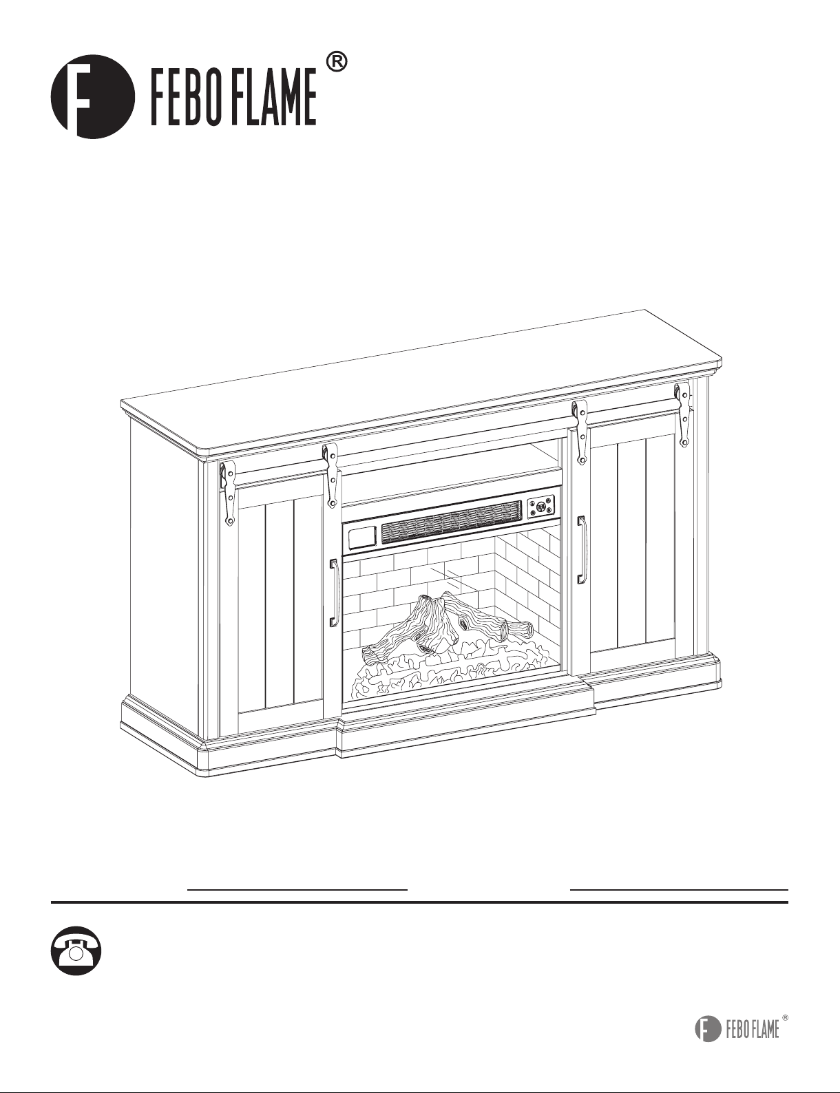
62IN BARN DOOR MANTLE WITH
3D FLAME AND WIFI SMART
ELECTRIC FIREPLACE

2
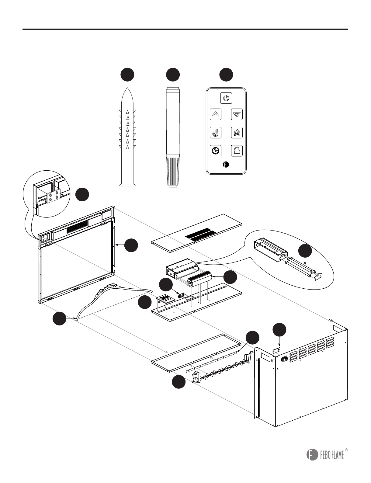
PACKAGE CONTENTS
A
B
C
D
E
F
G
H
I
J
K
L
M
N
O
P
Q
1
2
1
1
1
1
1
1
2
1
1
4
1
1
1
1
1
Center Panel
Connecting Wood
Left Middle Panel
Right Middle Panel
Bottom Frame
Left Side Panel
Right Side Panel
Front Rail
Back Panel
Back Rail
Top Frame
Adjustable Shelf
Removable Back Panel
Left Door
Right Door
Electric Insert
Remote Control
No-tool Assembly Hardware
PART PARTQUANTITY QUANTITYDESCRIPTION DESCRIPTION
(Preassembled To Left Side Panel (F),
Left Middle Panel (C), Right Middle Panel
(D), Right Side Panel (G))
Glide
(Preassembled To Left Door (N), Right Door (O))
Rear Rail
S
T
4
1
R8
D
C
T
M
I
I
F
P
Q
E
N
J
K
O
S
R
L
L
L
L
BB
A
H
G

3
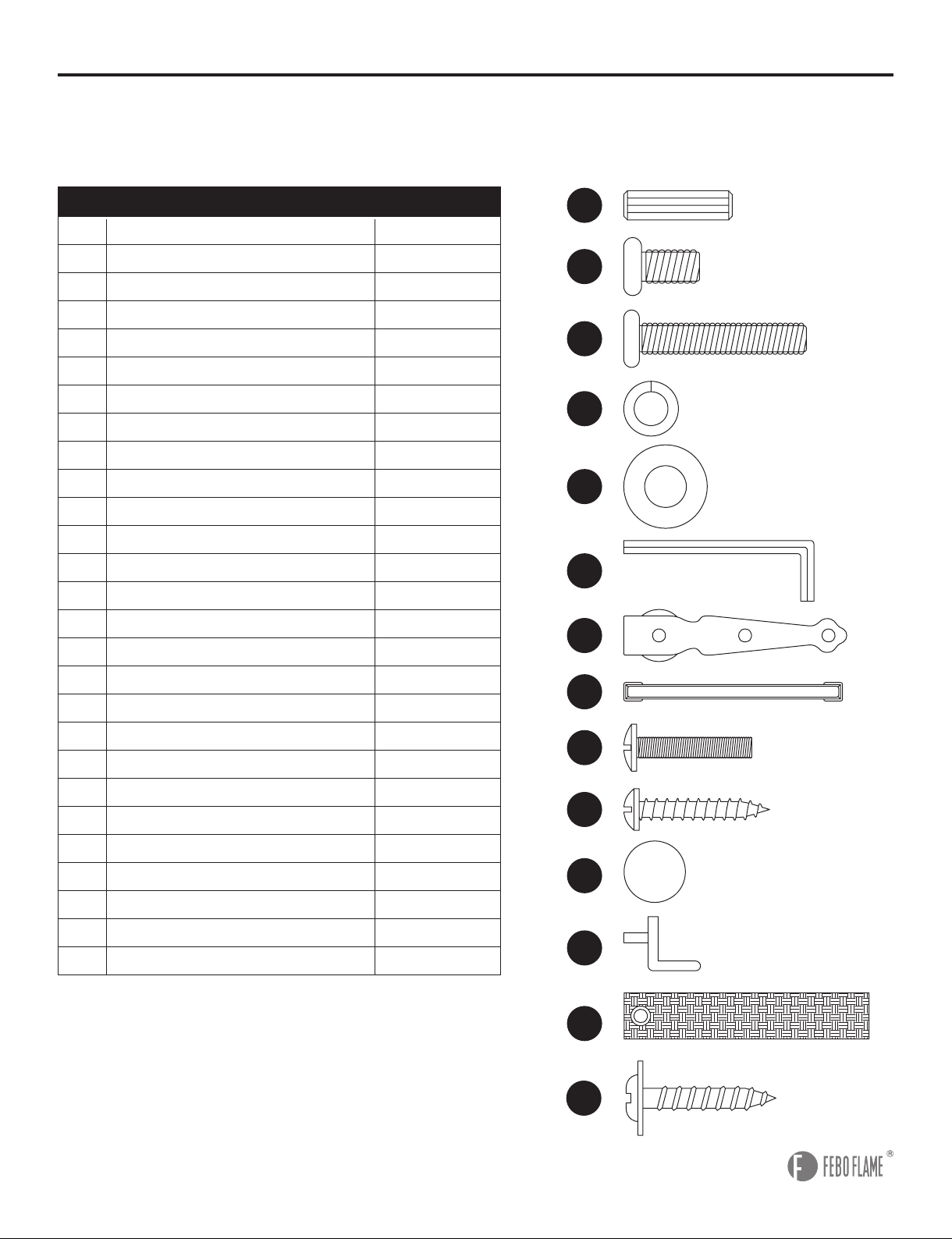
HARDWARE CONTENTS (not shown actual size)
AA
GG
OO
BB CC
HH
PP
DD
II
QQ
EE
JJ LL
NN
MM
FF
Wood Dowel
Qty. 24
Sliding Hardware
Qty. 4
Tipping Prevention Device
Qty. 2
Short Hex Bolt
Qty. 8
Long Hex Bolt
Qty. 10
Spring Washer
Qty. 10
Handle Bolt
Qty. 4
Wall Anchor
Qty. 2
Touch-up Pen
Qty. 1
Long Screw
Qty. 5
Handle
Qty. 2
Short Screw
Qty. 4
Flat Washer
Qty. 14
Plastic Pad
Qty. 2 Shelf Pin
Qty. 16
Hex Wrench
Qty. 1
AC AD
Corner Wood
Qty. 8
Screw
Qty. 8

4
SAFETY INFORMATION
Please read and understand this entire manual before attempting to assemble, operate or install the
product. When using electrical appliance, basic precautions should always be followed to reduce the
risk of re, electric shock and injury to persons including the following:
• This appliance is hot when in use. To avoid burns, do not let bare skin touch hot surface. If provided,
use handles when moving this appliance. Keep combustible materials -- such as furniture, pillows,
bedding, papers, clothes and curtains, etc. -- at least 3 feet away from the front of the appliance.
Keep all items away from the sides and rear.
• Extreme caution is necessary when the appliance is used by or near children or invalids and
whenever the appliance is left operating and unattended.
• Always unplug appliance when not in use.
• Do not operate any appliance with a damaged cord or plug or after the appliance malfunctions,
has been dropped or damaged in any manner. Return appliance to authorized service facility for
examination, electrical or mechanical adjustment or repair.
• Do not use outdoors.
• This appliance is not intended for use in bathrooms, laundry areas and similar indoor locations.
Never locate appliance where it may fall into a bathtub or other water container.
• Do not run cord under carpeting. Do not cover the power cord with throw rugs, runners or similar
oor coverings. Arrange cord away from trafc area and where it will not be tripped over.
• To disconnect the appliance, turn all controls “OFF”, then remove the plug from the electrical outlet.
• Connect to properly grounded outlets only.
• Do not insert or allow foreign objects to enter any ventilation or exhaust openings as this may cause
an electric shock or re, or damage the appliance.
• To prevent a possible re, do not block air intakes or exhausts in any manner. Do not use on soft
surfaces, like a bed, where openings may become blocked.
• All electrical appliances have hot and arching or sparking parts inside. Do not use in areas where
gasoline, paint or ammable liquids are used or stored.
• Use this appliance only as described in this manual. Any other use not recommended by the
manufacturer may cause re, electric shock or injury to persons.
• Avoid the use of an extension cord as it may overheat and cause a risk of re. However, if an
extension cord MUST be used, the cord must be No. 14AWG minimum size and rated not less than
1875 watts. The extension cord must be a 3-prong cord with grounding type plug and cord
connection and should not exceed 20 feet in length.
• When transporting or storing the appliance, take care to keep both the unit and power cord/plug dry,
free from excessive vibration and away from heat sources.
• Do not attempt to burn wood or other materials in this appliance.
• This appliance, when installed must be electrically grounded in accordance with the current CSA
C22.1 Canadian Electrical codes or for USA installations, follow local codes and the National
Electric Code, ANSI/NFPA NO.70.
• This unit should be operate under supervision and should not be left on without supervision.
• It is strongly recommended that to use the entire 15 amp outlet for the electric replace only.
• Sharing the outlet with another electronic item could create overload and damage the outlet and
electric items in the long term.
SAVE THESE INSTRUCTIONS

5
CAUTION
Two people are required to lift this item. It is heavy and will break if dropped.
WARNING
• Do not fully tighten the bolts on the assembly until mantel is completed. Positioning of the mantel
pieces during assembly will be easier if there is some exibility between the different pieces. Tighten
all bolts after the assembly is complete and before the insert is set inside.
• Do not use this replace in wet or moist locations.
• To reduce the risk of re, electric shock or injury to persons, disconnect and unplug the power
cord and let cool for at least 10 minutes before attempting any maintenance, cleaning or service for
the electric insert. Only a qualied professional should attempt to service or repair the appliance.
• Do not dispose of batteries of remote control in re. Improper disposal may cause batteries to leak
or explode.
• The preassembled battery in the remote control is not rechargeable; do not recharge the battery.
• Remove the batteries from remote control once they have expired.
• Be sure to insert the battery with the correct polarity.
• Do not ingest the battery; keep the battery away from babies and children.
PREPARATION
Before beginning assembly of product, make sure all parts are present. Compare parts with
package contents list and hardware contents list. If any part is missing or damaged, do not
attempt to assemble the product.
Estimated Assembly Time: 30 minutes
Tools Required for Assembly (not included): Phillips Screwdriver
Warning: Changes or modications to this unit not expressly approved by the party responsible for
compliance could void the user’s authority to operate the equipment.
NOTE: This equipment has been tested and found to comply with the limits for a Class B digital
device, pursuant to Part 15 of the FCC Rules. These limits are designed to provide reasonable
protection against harmful interference in a residential installation. This equipment generates,
uses and can radiate radio frequency energy and, if not installed and used in accordance with the
instructions, may cause harmful interference to radio communications.
However, there is no guarantee that interference will not occur in a particular installation. If this
equipment does cause harmful interference to radio or television reception, which can be determined
by turning the equipment off and on, the user is encouraged to try to correct the interference by one
or more of the following measures:
• Reorient or relocate the receiving antenna.
• Increase the separation between the equipment and receiver.
• Connect the equipment into an outlet on a circuit different from that to which the receiver is connected.
• Consult the dealer or an experienced radio/TV technician for help.

6
ASSEMBLY INSTRUCTIONS
1
1. Attach connecting wood (B) to each side of center
panel (A) using long hex bolt (CC), spring washer
(DD) and at washer (EE). Tighten with Hex wrench
(FF).
2. Insert wood dowels (AA) into each side of center
panel (A). Line up holes on left middle panel (C) and
right middle panel (D) with wood dowels (AA) and
attach to center panel (A) using long hex bolt (CC),
spring washer (DD) and flat washer (EE). Tighten
with hex wrench (FF).
Hardware Used
Hardware Used
AA
DD
DD
CC
CC
EE
EE
FF
FF
Wood Dowel
Spring Washer
Spring Washer
Long Hex Bolt
Long Hex Bolt
Flat Washer
Flat Washer
Hex Wrench
Hex Wrench
x 4
x 4
x 4
x 4
x 4
x 4
x 4
x 1
x 1
Note: Do not fully tighten the bolts on the assembly until mantel is completed. Assemble the item as
close to its nal location as possible.
2
EE
FF
CC
DD
A
A
B
B
EE
FF
AA
AA
CC
DD
C
D
A
7
AA
AA
Wood Dowel
Wood Dowel
x 4
x4
ASSEMBLY INSTRUCTIONS
4
3
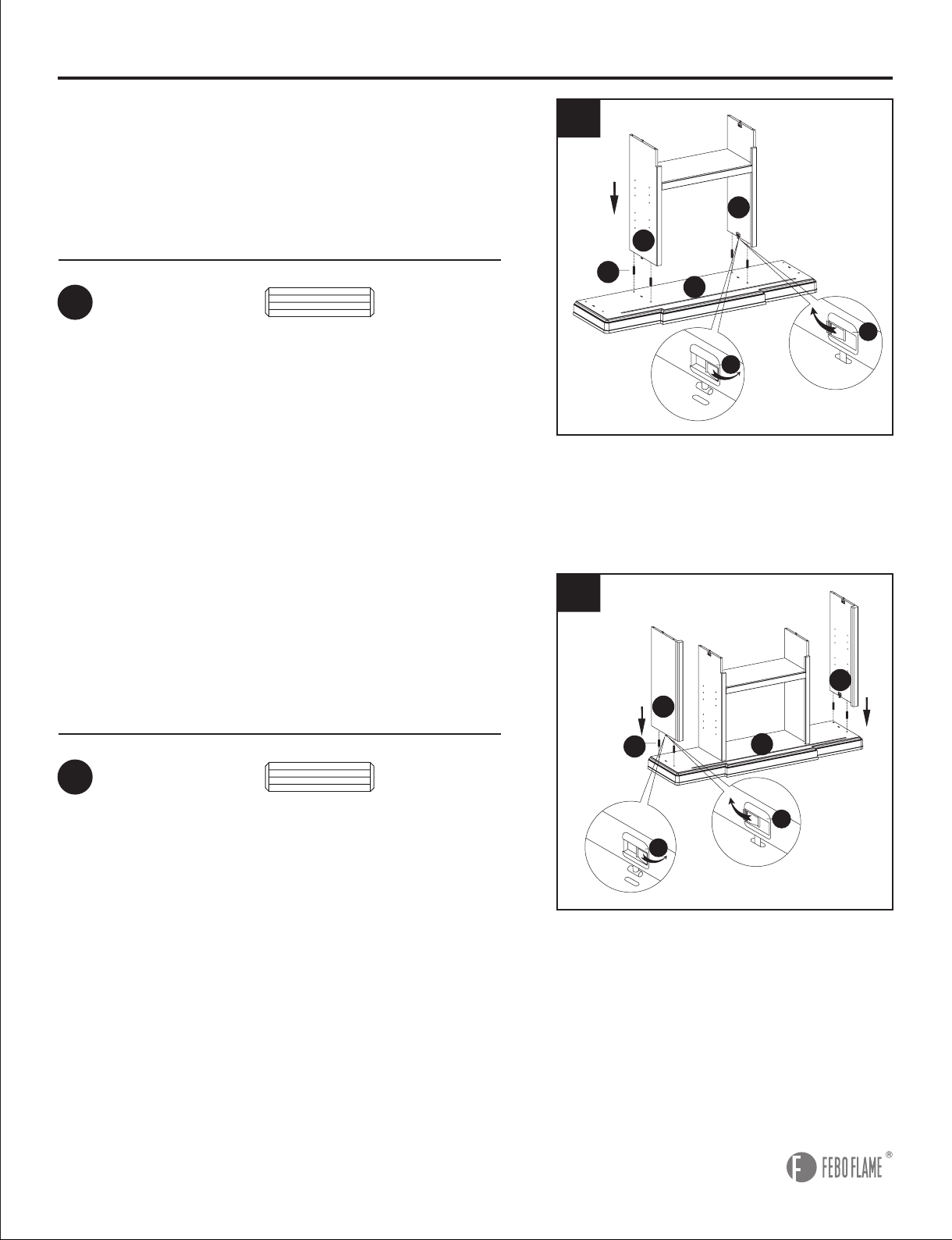
4. Insert wood dowels (AA) into bottom frame
(E). Line up holes on left side panel (F) and right
side panel (G) with wood dowels (AA) and attach
to bottom frame (E) by closing no-tool assembly
hardware (R).
3. Insert wood dowels (AA) into bottom frame (E).
Line up holes on left middle panel (C) and right
middle panel (D) with wood dowels (AA) and attach
to bottom frame (E) by closing no-tool assembly
hardware(R).
Hardware Used
Hardware Used
AA
E
F
G
R
R
R
R
Open
Closed
AA E
F
G
AA
D
C
E
R
R
R
R
Open
Closed
AA
C
D
E
8
ASSEMBLY INSTRUCTIONS
6
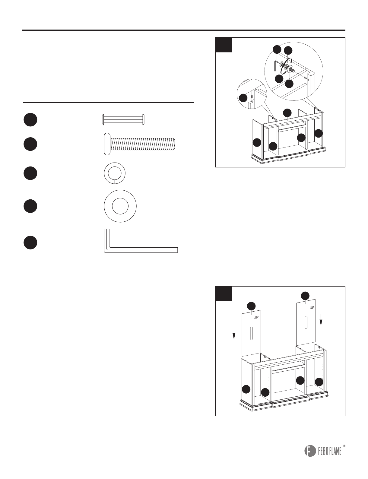
6. Insert one back panel (I) down along the groove of
left side panel (F) and left middle panel (C) and the
other back panel (I) down along the groove of right
side panel (G) and right middle panel (D).
5. Insert wood dowels (AA) into left middle panel (C)
and right middle panel (D). Line up holes on front
rail (H) with wood dowels (AA) and attach to left side
panel (F) and right side panel (G) using long hex
bolt (CC), spring washer (DD) and at washer (EE).
Tighten with hex wrench (FF).
Hardware Used
5
EE
CC
FF
AA
DD
H
G
F
I
F
G
I
D
C
I
I
D
F
G
C
DD
CC
EE
FF
Spring Washer
Long Hex Bolt
Flat Washer
Hex Wrench
x 2
x 2
x 2
x 1
AA Wood Dowel x 2
C
D

9
Hardware Used
ASSEMBLY INSTRUCTIONS
8
7. Attach back rail (J) to top frame (K) with wood
dowels (AA) and long screw (JJ). Tighten with Philips
screwdriver.
Insert wood dowels (AA) into left side panel (F), left
middle panel (C), right middle panel (D) and right
side panel (G). Set top frame (K) over left side panel
(F), left middle panel (C), right middle panel (D)
and right side panel (G). Secure by closing no-tool
assembly hardware (R).
8. Install shelf pins (MM) and insert adjustable
shelves (L) into desired locations in cabinets of
mantel.
Hardware Used
7
L
L
KK
MM
L
L
AA
JJ
MM
Wood Dowel
Long Screw
Shelf Pin
x 10
x 3
x 16
R
R
Open
Closed
Front
Back
AA
AA
JJ
J
J
J
D
J
F
J
C
K
K
G

10
ASSEMBLY INSTRUCTIONS
9. Insert the glides (S) into the groove on bottom
frame (E). Hang sliding hardware (GG) on the metal
rail so the wheel rolls smoothly. Align the holes in
sliding hardware (GG) with the holes in the door and
attach sliding hardware (GG) to the door with short
hex bolt (BB). Tighten with hex wrench (FF). Attach
the plastic pad (LL) to left door (N) and right door (O).
Hardware Used
GG
LL
Sliding Hardware
Plastic Pad
x 4
x 2
BB Short Hex Bolt x 8
FF Hex Wrench x 1
9
S
FF
LL
GG
BB
N
E
O
10
Hardware Used
HH
II
Handle
Handle Bolt
x 2
x 4
10. Insert handle bolt (II) through backside of left
door (N) and right door (O) and attach handle (HH).
Tighten handle bolt (II) with Phillips screwdriver to
secure handle (HH).
NO
I I
HH

11
ASSEMBLY INSTRUCTIONS
11. From backside of mantel assembly, attach
removable back panel (M) into groove on center
panel (A).
11
MA
A
12
12. Still from the backside of the assembly, and
with the assistance of another person, insert the
electric insert (P) into the opening. Then, attach
rear rail (T) to bottom center panel (A) and bottom
frame (E) using long screw (JJ). Tighten with Phillips
screwdriver. Then, attach corner wood (AD) to corner
back panel (I) using screws (AC). Tighten with Philips
screwdriver.
Hardware Used
JJ
AC
Long Screw
Screw
x 2
x 8
P
E
I
I
TA
JJ
AD
AC

12
ASSEMBLY INSTRUCTIONS
13
13. Attach the tipping prevention device (NN) to the
back top frame (K) with flat washer (EE) and short
screw (OO). Tighten with Philips Screwdriver. Place
the mantel in the desired location and mark the wall
behind the tipping prevention device (NN). Remove
the mantel and drill a hole for the wall anchor (PP)
at the marked location. Insert the wall anchor (PP)
into the wall. Replace the mantel back into position
and secure the tipping prevention device (NN) with
at washer (EE) and short screw (OO). Tighten with
Philips Screwdriver.
Hardware Used
OO
PP
Short Screw
Wall Anchor
Tipping
Prevention
Device
x 4
x 2
x 2
C
K
PP
EE
EE
NN
NN
OO
OO
NOT INCLUDED
NOT INCLUDED
WALL
WALL
EE Flat Washer x 4
NN

13
Grounding Pin
Grounding
Means
Adapter
Matel Screw
Cover of Grounding
Outlet Box
1
1. Ensure all controls are in the “OFF” position before
plugging the appliance into a properly grounded
electrical outlet. This appliance is for use on 120 volts.
The appliance has a 3-prong grounded plug. If your
electrical outlet has only 2 slots, you will have to use
an adapter to convert from the 3-prong power cord to a
2-slot receptacle. The green grounding plug extending
from the adapter must be securely connected to a
permanent ground such as a properly grounded outlet
box. The adapter should only be used if a proper 3-slot
receptacle is not available.
Note: Adapters are not allowed for use in Canada.
2. A-15-amp circuit is required to operate this appliance.
If the breaker trips when the appliance is running, you
may need to move the appliance to another location or
unplug other appliances that are on the same circuit.
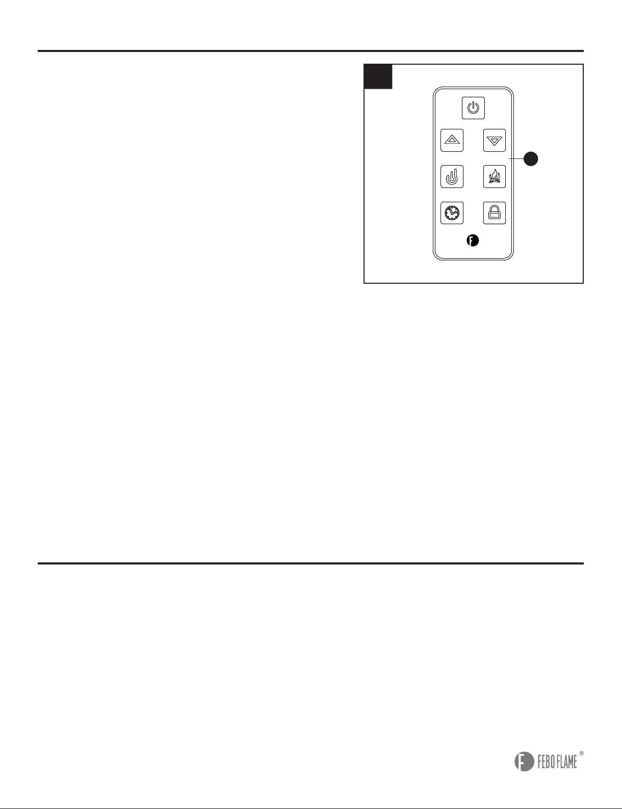
The replace control functions can be accessed in three
ways: Using the control panel, located in the upper
right-hand corner of the electric insert (P), or using the
remote control (Q), or using the APP.
3. If the appliance is on, you press any button (except
POWER) on the control panel or on the remote
control (Q), the digital display screen will show the
corresponding numbers of ame, heat or timer. Without
any further operation, the digital display screen will
show room temperature after 15 seconds. Then there is
no display after 5 more seconds.
Note: For safety, the appliance will automatically turn
off when the doors are closed or barrier influence in
front of the appliance.
OPERATING INSTRUCTIONS
3
P
2
Control Panel
Q
14
4
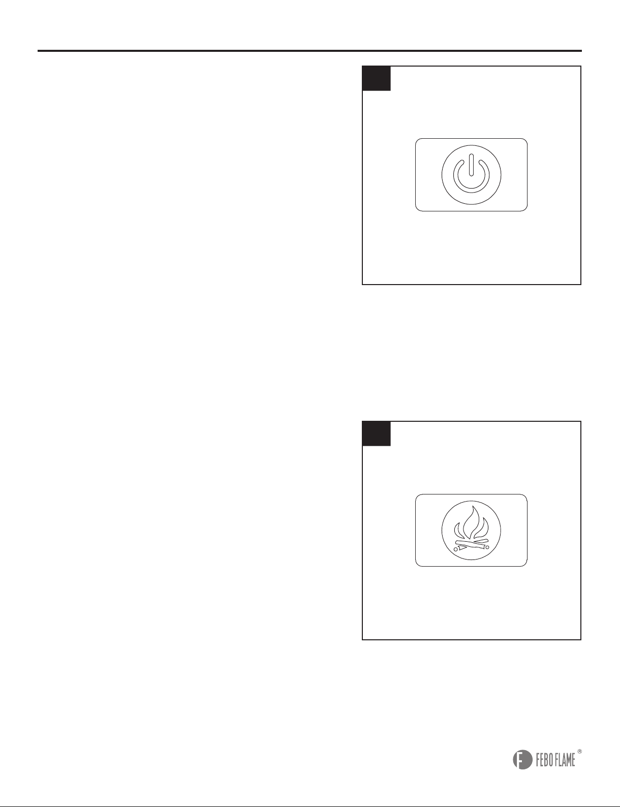
4. Power: Push button to turn on or turn off. If ON, the
digital display screen will show the room temperature,
the ame is on. If OFF, all functions except Timer will be
restored at the next power ON.
Note: Unplugging the unit will reset all functions.
5. Flame: Press to activate the flame function. The
FLAME button controls the flame and ember effect.
When the replace is rst turned on, the default state is
amber ame. When you press Flame button continually,
there are 5 selections you can cycle through, including
Amber, Midnight, Polar, Hearth (Flame OFF, the ember
remains on) and Violet, the digital display screen will
show corresponding letter of flame as A, M, P, H, U.
Note: Press UP or DOWN button on the remote control
to adjust the brightness of flame except Polar mode.
There are 5 levels of the brightness, the digital display
screen will show the corresponding numbers.
Note: Press and hold the FLAME button for 5 seconds
to activate the child lock function. When the CHILD
LOCK is on, all the other features are disabled, and
the digital display screen will show--. Press and hold
the FLAME button again for 5 seconds to unlock the
function.
OPERATING INSTRUCTIONS
5

15
7. Timer: Press and hold the button for 1.5 seconds
to activate or deactivate the timer function. The default
state is 0.5 hour. Press the Timer button continually on
the control panel, or press UP or DOWN button on the
remote control to adjust the timer. The choices are 0.5H,
between 1H to 8H with 1H interval. Once the TIMER is
on and the desired setting is reached, the system will
shut down.
OPERATING INSTRUCTIONS
7
6
6. Heater: Press and hold the button for 1.5 seconds to
activate or deactivate
the heater function. The system
will start the default temperature setting at 80°F/27°C.
There are 7 adjustable heat levels, ranging from
90°F/32°C to 60°F/16°C. Press the button again to adjust
the heat levels, or press the UP or DOWN button on
the remote control to adjust the levels, noting each level
increases or decreases the temperature by 5°F. When
the heater is on, digital display screen will show the
setting temperature corresponding numbers. And when
this feature is off, the inner blower will continue to run
for additional 1 minutes to cool down the unit in order to
protect the heating elements before the unit completely
shuts off.
Note: You can switch the temperature display from
Fahrenheit to Celsius by pressing and holding the
HEATER button on the remote control for approximately
3 seconds. Without any further operation, the digital
display screen will show room temperature after 15
seconds. Then there is no display after 5 more seconds.
16
CARE AND MAINTENANCE
• Keep the replace in a climate-controlled environment. Extreme temperature and humidity changes
can cause warping, shrinking and/or splitting of wood.
• Use a clean dry cloth to clean the replace.
• Clean metal surfaces of electric insert with a clean damp cloth, making sure not to push dust or
debris into any air intake or exhaust vents.
• Do not use abrasive cleaners or spray liquids on any part of the appliance.
• Periodic cleaning/vacuuming of the fan/heater unit is strongly recommended to ensure that no dirt
or foreign objects build up.
• Battery Replacement: Use one lithium coin cell battery (size CR2025) for the remote control.
• Use the touch-up pen (QQ) to repair minor scratches and damages on mantel.
OPERATING INSTRUCTIONS
8
8. Buttons on the Remote Control (Q) have the same
functions as those on the Control Panel except Heater
and Timer.
Heater: On the remote control (Q), press this button
immediately activate or deactivate the heater function.
Press the UP or DOWN button to adjust the heat level.
Timer: On the remote control (Q), press this button
immediately activate or deactivate the timer function.
Press the UP or DOWN button to adjust the timer.
Child Lock: Press this button immediately activate or
deactivate the function.
Down: Use to turn down the heat, brightness of ame
or timer. When FLAME / HEATER / TIMER is not
activated, press this button can adjust the brightness of
ame.
Up: Use to turn up the heat, brightness of flame
or timer. When FLAME / HEATER / TIMER is not
activated, press this button can adjust the brightness of
ame.
CAUTION: The Remote Control (Q) comes preassembled
with a correct battery, but you must remove the insulation
plastic lm from the battery before operation.
Q

17
TROUBLESHOOTING
SOLUTION
PROBLEM POSSIBLE CAUSE
1. Push ame button to increase light.
2. Contact customer service center.
3. Remove screws holding back panel
in place and remove back panel.
Secure end of “Flame wand” back
into the support bracket.
4. Contact customer service center.
1. Turn all controls off, unplug the
appliance, allow the insert to cool
down for at least 10 minutes, and
then plug in and restart.
2. Reset house circuit breaker.
Turn all controls off, unplug the
appliance, allow the insert to cool down
for at least 10 minutes, and then plug
in and restart.
1. Replace all batteries in the remote
control.
2. Operate the remote at a distance
less than 20 feet from the front of the
appliance; point the remote at the
control panel.
1. Low batteries.
2. Distance.
The overheat protection
device in the appliance
has been triggered.
1. The overheat protection
device in the appliance
has been triggered.
2. House circuit breaker
has been tripped.
1. Dimmer control button
is set too low.
2. LED strip not
functioning.
3. “Flame wand” has come
loose from bracket.
4. “Flame wand” motor is
not functioning.
Simulated ame
effect is dim or not
present.
The appliance
turns off and will
not turn back on.
The appliance does
not turn on when
the button is pushed
to “ON”.
Remote control
does not work.
WARRANTY
The manufacturer warrants this item against defects in materials and workmanship for a period of one
(1) year from the date of original retail purchase. This warranty applies only to the original purchaser.
This warranty does not apply to any damage on the product by accident, misuse, or modified,
improper installation or by afxing accessories not produced by the manufacturer. The manufacturer
is not accountable whatsoever for product installation during the warranty period. There is no further
expressed warranty. The manufacturer shall not be legally responsible for incidental, consequential
or special damages arising at or in connection with product use or performance except as may
otherwise be accorded by law. The manufacturer disclaims any and all implied warranties.
18
REPLACEMENT PARTS LIST
For replacement parts, call our customer service department at 1-877-355-3326 or 1-925-820-8478,
9 a.m. - 4 p.m., EST, Monday - Friday. Email: [email protected]
AA
BB
HH
CC
II
DD
JJ
LL
EE
MM
NN
FF
PART PART #
DESCRIPTION
Q
AA
BB
CC
DD
EE
FF
GG
HH
II
JJ
LL
MM
NN
OO
PP
QQ
RR
SS
TT
UU
VV
WW
XX
YY
ZZ
AB
Remote Control
Wood Dowel
Short Hex Bolt
Long Hex Bolt
Spring Washer
Flat Wahser
Hex Wrench
Sliding Hardware
Handle
Handle Bolt
Long Screw
Plastic Pad
Shelf Pin
Tipping Prevention Device
Short Screw
Wall Anchor
Touch-up Pen
Blower
Quartz Tube
LED Light Board
Wooden Log
Control Panel
Light Sensor
Front Frame
Heater Sensor
Flame Generator Driver Motor
Mother Board
2019-411001
2019-401001
2019-402001
2019-402002
2019-402003
2019-403001
2019-404001
2019-405001
2019-406001
2019-406002
2019-407001
2019-409001
2019-412001
2019-413001
2019-414001
2019-415001
2019-416001
2019-417001
2019-418001
2019-415002
2019-419001
2019-422001
2019-423001
2019-424001
2019-425001
2019-426001
2019-427001
GG
OO
19
REPLACEMENT PARTS LIST
For replacement parts, call our customer service department at 1-877-355-3326 or 1-925-820-8478,
9 a.m. - 4 p.m., EST, Monday - Friday. Email: [email protected]
Q
Printed in Vietnam
VV
XX
YY
ZZ
AB
WW
RR
SS
TT
UU
QQPP
20
ARTÍCULO #1279103
¿Preguntas, problemas, piezas faltantes? Antes de volver a la tienda, llame al Servicio al
Cliente al 1-877-355-3326 o 1-925-820-8478, de lunes a viernes de 8 a.m. a 8 p.m., hora
estándar del Este. Correo electrónico: [email protected]
MODELO#F18-I-008-018C
ADJUNTE SU RECIBO AQUI
Número de serie Fecha de compra
REPISA PARA CHIMENEA TIPO
PUERTA DE GRANERO DE
157,48 CM CON LLAMA 3D Y CHIMENEA
ELÉCTRICA INTELIGENTE CON WIFI
Table of contents
Languages:
Other Febo Flame Indoor Fireplace manuals

Febo Flame
Febo Flame F16-I-006-089 User manual

Febo Flame
Febo Flame 16IN-32-E User manual

Febo Flame
Febo Flame ZHS-32-D User manual

Febo Flame
Febo Flame CYFPINS01 User manual

Febo Flame
Febo Flame 17IN-42-118 User manual

Febo Flame
Febo Flame ZHS-32-F User manual

Febo Flame
Febo Flame F19-C-041-138 User manual

Febo Flame
Febo Flame 18IN-23-130 User manual
Popular Indoor Fireplace manuals by other brands

Pacific energy
Pacific energy NEO 1.6 INSERT Installation and operating instructions

Valor
Valor quantum BR644 VA owner's guide

Valor
Valor 650JN Installation & owner's manual

Totem
Totem INSERT 600 operating instructions

Majestic
Majestic SB6000 Installation, operation and maintanance manual

decoflame
decoflame Denver user manual


