FED 5B Manual

FED 5B Instructions for Use, 1992
–1 –
FED 5B
Instructions for Use, 1992.
IMPORTANT:
Set the shutter speeds only when the shutter has been cocked. Do not turn the exposure head in the
interval between “30” and “1”. Failure to comply with these requirements results in breaking of the
camera.
Since efforts are continually made to improve the reliability and performance of the product, minor
changes may be introduced without special notice.
1. General Directions
Camera FED 5B is intended for amateur and professional shooting on standard black-and-white and
colour perforated film 35 mm wide.
The camera is simple in handling. Fulfilment of the rules set forth in the present manual ensures its
reliable operation for many years.
While handling the camera, do not exert excessive efforts, protect it from dust, avoid to touch its
optics.
The design of the camera is protected by the USSR inventors’ certificates Nos 773562, 313194.
2. Specifications
Picture size, mm . . . . . . . . . . . . . . . . . . . . . . .
24×36
Film magazine load . . . . . . . . . . . . . . . . . . . . .
film 1.65 m long for 36 pictures
Lens . . . . . . . . . . . . . . . . . . . . . . . . . . . . . . . . .
anastigmat INDUSTAR-61 Л/Д; 1 : 2.8; f =55 mm
Lens fastening thread . . . . . . . . . . . . . . . . . . .
M 39×1 mm
Coupling dimensions for attachments, mm:
plane . . . . . . . . . . . . . . . . . . . . . . . . . . . . . .
42
threaded . . . . . . . . . . . . . . . . . . . . . . . . . . .
M 40.5×0.5
Focusing range . . . . . . . . . . . . . . . . . . . . . . . .
from 1 m to ∞ (infinity)
View finder . . . . . . . . . . . . . . . . . . . . . . . . . . .
optical, combined with range finder,
provided with dioptric correction of ±2D
Shutter . . . . . . . . . . . . . . . . . . . . . . . . . . . . . . .
curtain-type, with speeds from 1 to 1/500 s
and “B”(by hand)
Automatic releaser . . . . . . . . . . . . . . . . . . . . .
X-contact, for electronic flash lamps
Synchronizer . . . . . . . . . . . . . . . . . . . . . . . . . .
mechanical
Tripod thread . . . . . . . . . . . . . . . . . . . . . . . . .
1/4″
Mass of camera in case, kg . . . . . . . . . . . . . . .
0.96

FED 5B Instructions for Use, 1992
–2 –
3. Delivery Set
Camera . . . . . . . . . . . . . .
1
Film magazine . . . . . . . .
1
Lens cap . . . . . . . . . . . . .
1
Clip stopper . . . . . . . . . .
1
Case . . . . . . . . . . . . . . . .
1
Instructions for Use . . . .
1
Packing box . . . . . . . . . .
1
4. Design
The main units of the camera are as follows: the body which houses the mechanisms of the shutter,
automatic releaser, synchronizer, range-and-view finder, picture counter and the lens with diaphragm,
depth-of-field, and distance scales. The lens is attached to the body with the aid of a thread.
The camera controls and functional units are shown in Figs 1 and 2.
Fig. 1
1 —automatic releaser cocldng lever;
2 —automatic releaser button;
3 —range finder aperture;
4 —shutter release button;
5 —clip stopper;
6 —clip with synchronizer contact;
7 —view finder aperture.

FED 5B Instructions for Use, 1992
–3 –
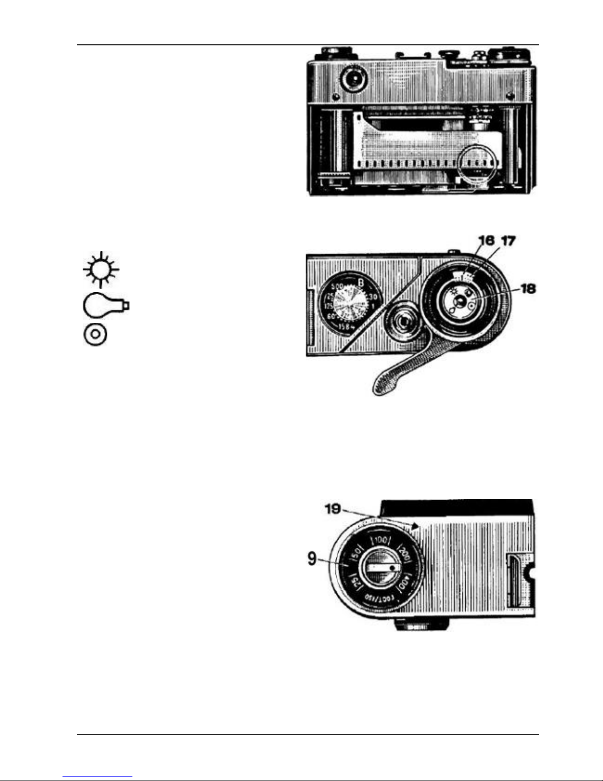
Fig. 2
08 —dioptric correction ring;
09 —film sensitivity indicator limb;
10 —rewinding knob;
11 —exposure head;
12 —exposure scale;
13 —disconnector sleeve;
14 —shutter cocking lever;
15 —camera cover.
5. Preparation for Operation
Preparation of the camera for shooting consists
in its loading by the magazine with a film.
The loading is carried out under ordinary soft
lighting conditions.
Undo the screw fixing the camera in the case.
Remove the camera from the case.
Raise the lock shackles of camera cover 15
(Fig. 2) and turn them half-way round as far as
they go according to Fig. 3. Then pressing with
the thumbs on the cover, shift it in the direction
of an arrow, as shown in Fig. 4, and take off the
camera.
Put the magazine with a film into the camera
recess. Insert the end of the film into the slot in
the take-up reel as shown in Fig. 5.
Turning the shutter cocking lever 14 (Fig. 2)
pull the film so that its perforations should get
onto the teeth of both rims of the feeding drum.
Close the camera by the cover and push its
edge under the shield. Turn the lock shackles
half-way round and lower them into the
recesses.
To feed the unexposed film to the picture
aperture, cock the shutter twice, pressing on
release button 4(Fig. 1) after each cocking.
The shutter cocking lever should be turned
each time as far as it goes, otherwise the button
will be interlocked and the shutter will not
operate upon pressing on the button.
Fig. 3
Fig. 4
FED 5B Instructions for Use, 1992
–4 –
After the second-third cocking picture
counter limb 17 (Fig. 6) will set opposite digit
“1”and will show the first frame prepared for
shooting.
For convenience in use the shutter cocking
lever has two positions: operating and transport
In the operating position the end of the lever
protrudes beyond the camera shield.
Shown in Fig. 6 and 7 are a film type and a
film sensitivity indicator limbs.
The film type indicator limb is arranged on the
picture counter. The conventional designations
of the film types drawn up on the limb are as
follows:
—colour film for day light;
—colour film for artificial light;
—black-and-white film.
Having loaded the camera, turn limb 18 until
the symbol, corresponding to the type of a film
by which you have loaded the camera, coincides
with index 16 on the counter.
Then turn limb 9until the number
corresponding to the sensitivity of the film
loaded into the camera coincides with index 19.
The indicator limbs will help you to
remember by what type of the film the camera
has been loaded when you want to take pictures
after a long interval.
6. Operating Procedure
So, you have loaded the camera and may
begin loading.
Having chosen the place for shooting, open
the camera case, take the cap off the lens and
locking through eyepiece 20 (Fig. 8) of the
view-and-range finder check how the chosen
subject is arranged within the field of vision of
the view finder.
In order to set the camera at an accurate focus
first turn dioptric correction ring 8(Fig. 2),
focus the view-finder by your own sight.
Focus the lens. With this purpose by turning
distance scale 23 (Fig. 10) align two images
seen in the circle of the field of vision of the
view finder, as shown in Fig. 9, into one.
Fig. 5
Fig. 6
16 —picture counter index;
17 —picture counter limb;
18 —film type indicator limb.
Fig. 7
19 —film sensitivity indicator index.

FED 5B Instructions for Use, 1992
–5 –
When photographing the remote subjects or if
the distance to the subject to be photographed is
known the lens may be focused by the distance
scale.
In case of photographing the objects having a
considerable extension to the depth or when
shooting a series of subjects located at different
distances from the camera, determine the value
of the necessary diaphragm with the aid of the
depth-of-field scale and diaphragm the lens by
setting diaphragm scale 21 in the required
position relative to the index.
Depth-of-field scale 22 consists of two rows
of numbers corresponding to the lens diaphragm
scale and disposed symmetrically relative to
distance scale index 24.
When the lens is being focused, the depth-of-
field scale shows on the distance scale the
shortest and longest distances from the camera
within which the image sharpness will be
satisfactory for each diaphragm value chosen in
shooting.
For example, in Fig. 10 you can see that
when the lens is focused at a distance of 3 m, the
diaphragm being 5.6, all the subjects located at a
distance of 2.5 to 4 m from the camera will be
sharply photographed. When the diaphragm is
equal to 8 the subjects located from 2.2 to 5 m
from the camera are sharply photographed on
the picture and so on.
Determine the shutter speed required for
shooting. You can easily do it with the aid of a
pocket exposure meter or exposure metering
tables.
To protect the lens from the overhead-and-
side light it is good practice to put a sunshade
on the lens in shooting.
Having determined the value of the required
exposure, raise slightly exposure head 11 (Fig.
11), turn it till the index registers with the
chosen value on exposure scale 12 and lower it,
in this case the head should be fixed in the set
position.
In Fig. 11 the head is set at the exposure
(shutter speed) of 1/30 s.
The exposure can be set only with the shutter
cocked. Do not turn the exposure head in the
interval between “30” and “1”.
Digits on scale 12 correspond to shutter
speeds of 1, 1/2, 1/4, 1/8, 1/15, 1/30, 1/60,
1/125, 1/250 and 1/500 s.
The dot between digits “1” and “4” on the
exposure limb corresponds to the shutter speed
Fig. 8
Fig. 9
Fig. 10
21 —diphragm scale;
22 —depth-of-field scale;
23 —distance scale;
24 —distance scale index.
Table of contents
Other FED Film Camera manuals


