FiberLogic OptiQwave-8310 User manual

Broadband Access Innovations
OptiQwave-8310
STM-1 Digital Microwave System
Installation Manual
Fiber Logic Communications, Inc.
5F-3, No.9, Prosperity Road One
Science-Based Industrial Park
Hsinchu, Taiwan
Tel: +886-3-5638889
Fax: +886-3-5638899
©2003 Fiber Logic Communications, Inc. Rev 2.0, 10/2003

©2003 Fiber Logic Communications, Inc. All rights reserved.
10/2003 Rev 2.0

- I -
Table of Contents
1. INTRODUCTION....................................................................................................................... 1
2. SYSTEM DESIGN ...................................................................................................................... 2
2.1 OPTIQWAVE-8310 FRONT PANEL .................................................................................. 2
2.2 OPTIQWAVE-8310 REAR PANEL..................................................................................... 2
3. SYSTEM FEATURES ................................................................................................................ 3
4. SYSTEM BLOCK DIAGRAM.................................................................................................. 5
5. TECHNICAL SPECIFICATION .............................................................................................. 7
5.1 RADIO (RF AND DIGITAL MODEM) INTERFACE ...................................................... 7
5.2 SDH INTERFACE ................................................................................................................ 7
5.2.1 STM-1 Optical Interface .................................................................................................. 7
5.2.2 STM-1 Electrical Interface............................................................................................... 8
5.3 SYSTEM MANGEMENT .................................................................................................... 9
5.4 ORDERWIRE INTERFACE ..............................................................................................11
5.5 ALARM OUTPUT RELAY.................................................................................................11
5.6 SYSTEM FUNCTIONALITIES........................................................................................ 12
5.7 LED STATUS INDICATION ............................................................................................. 13
5.8 TEST POINT ....................................................................................................................... 13
5.9 POWER SUPPLY................................................................................................................ 14
5.10 OPERATION TEMPERATURE ..................................................................................... 14
5.11 DIMENSION...................................................................................................................... 14
5.12 EMI..................................................................................................................................... 14
5.13 MTBF (MEAN TIME BETWEEN FAILURE) .............................................................. 14
6. SYSTEM INSTALLATION & TEST...................................................................................... 15
6.1 POWER................................................................................................................................ 15
6.2 ANTENNA INSTALLATION ............................................................................................ 15
6.3 TRANSMISSION LINE (RF INTERFACE) .................................................................... 16
6.4 RF OUTPUT POWER ADJUSTMENT............................................................................ 16
6.5 ALIGNMENT ...................................................................................................................... 17
6.6 LOOPBACK & PRBS BER TEST .................................................................................... 17
6.7 SONET/SDH INTERFACE (STM-1) ................................................................................ 18
6.8 CONSOLE (CID) INTERFACE ........................................................................................ 18
6.9 ETHERNET INTERFACE ................................................................................................ 21
6.10 ALARM OUTPUT RELAY.............................................................................................. 23
6.11 MODEM INTERFACE..................................................................................................... 23
6.12 ORDERWIRE INTERFACE ........................................................................................... 24
6.13 RS-232 INTERFACE ........................................................................................................ 24

- II -
6.14 TEST POINT INTERFACE ............................................................................................. 25
6.15 NOTE............................................................................................... 錯誤! 尚未定義書籤。
7. SYSTEM OPERATION ........................................................................................................... 26
7.1 POWER UP ......................................................................................................................... 26
7.2 RADIO (RF+DIGITAL MODEM) INTERFACE............................................................ 26
7.2.1 AIS OUT Mechanism..................................................................................................... 28
7.3 SONET/SDH (STM-1) INTERFACE ................................................................................ 29
7.4 SYSTEM LED INDICATION............................................................................................ 30
7.5 ETHERNET PORT AND LED INDICATION................................................................. 31
7.6 MENU TREE....................................................................................................................... 31
7.6.1 LCD Interface................................................................................................................. 34
7.6.2 CONSOLE (CID) & Modem Interface .......................................................................... 34
7.6.3 Telnet, SNMP and GUI (OS Interface) .......................................................................... 35
7.7 ALARM MONITORING.................................................................................................... 36
7.8 ALARM OUTPUT RELAY................................................................................................ 36
7.9 LOOPBACK AND PRBS TEST ........................................................................................ 37
7.10 SUMMARY AND STATISTICS REPORT ..................................................................... 38
7.11 ACO KEY........................................................................................................................... 38
7.12 ORDERWIRE ................................................................................................................... 38
7.13 REMOTE RS-232.............................................................................................................. 38
7.14 TEST POINT ..................................................................................................................... 38
8. SYSTEM SETTING.................................................................................................................. 39
8.1 CONSOLE (CID),
,,
,MODEM AND TELNET OPERATION......................................... 39
8.1.1 Connecting Method of CID, MODEM and Telnet Interfaces........................................ 39
8.1.2 The Control Key of CID Interface ................................................................................. 39
8.1.3 Switch Over the Near End to Far End............................................................................ 39
8.1.4 Configure RADIO Interface........................................................................................... 39
8.1.5 Configure SONET/SDH Interface ................................................................................. 41
8.1.6 Adjust RF Output Power ................................................................................................ 42
8.1.7 Retrive the Status of RADIO Interface .......................................................................... 42
8.1.8 Retrive the Status of RF Interface .................................................................................. 44
8.1.9 Copy the Near End Parameters to Far End .................................................................... 44
8.1.10 Retrive the Status & Alarm of Radio Interface ............................................................ 45
8.1.11 Retrive the Status and Alarm of SONET/SDH Interface ............................................. 46
8.1.12 Retrive and Clear the Alarm History............................................................................ 47
8.1.13 Loopback Test .............................................................................................................. 48
8.1.14 PRBS Testing ............................................................................................................... 49
8.1.15 Summary Table ............................................................................................................ 50
8.1.16 Current 7-Day PM Statistics of SONET/SDH Interface.............................................. 51
8.1.17 Current 1-Day PM Statistics Report of SONET/SDH Interface .................................. 51
.................................. 25

- III -
8.1.18 Current 1-Hour PM Statistics of SONET/SDH Interface ............................................ 52
8.1.19 Clear the PM Statistics of SONET/SDH Interface....................................................... 53
8.1.20 Retrive the Current System Parameters ....................................................................... 54
8.1.21 Set System Parameters ................................................................................................. 55
8.1.22 Set SNMP Parameters .................................................................................................. 56
8.1.23 Change User Name and Password ............................................................................... 57
8.1.24 OrderWire Setting and Calling..................................................................................... 59
8.1.25 Set Modem Parameters ................................................................................................ 60
8.1.26 Reset to Default............................................................................................................ 61
8.1.27 Restart .......................................................................................................................... 62
8.1.28 Logout .......................................................................................................................... 63
9. LCD INTERFACE OPERATION ........................................................................................... 65
9.1 LCD & KEY CONTROL ................................................................................................... 65
9.2 AN EXAMPLE OF LCD OPERATION............................................................................ 65
10. SNMP AND GUI INTERFACE (OS INTERFACE) ............................................................ 67
11. CUSTOMER SERVICE ......................................................................................................... 69
12. APPENDIX .............................................................................................................................. 70
12.1 MODEM INSTALLATION.............................................................................................. 70
12.2 RACK INSTALLATION .................................................................................................. 74
12.3 ALARM OUTPUT RELAY INSTALLATION............................................................... 75
12.4 LCD MENU TREE ........................................................................................................... 76
12.5 AGC VOLTAGE VERSUS RF RSL (DBM) DIAGRAM............................................... 78

- 1 -
Chapter 1
1. Introduction
The OptiQwave-8310 is a license-exempt (5.725~5.850GHz) digital microwave in ISM band
that provides STM-1 point-to-point wireless connections at the range of 1~50 km with high
availability. It complies with FCC Part 15, Subpart C 15.247 & 15.249. Fiber Logic allows you
to quickly add backhaul and backbone connections to your infrastructure. Because it is wireless,
Fiber Logic’s OptiQwave 8310 offers significant cost-savings compared to traditional leased lines.
In addition, fast deployment opens up new revenue streams and enables faster customer acquisition.
It also provides a time-to-market advantage when installing a leased-line is too costly or impossible.
155.52
Mbps
(SDH: STM
-
1)
(SONET: STS
-
3/OC
-
3)
Antenna
Antenna
Terminal
or
NMS
Order
Wire
Order
Wire
1
-
50
KM
155.52
Mps
(SDH: STM
-
1)
(SONET: STS
-
3/OC
-
3)
Application Diagram
OptiQwave-8310
OptiQwave-8310

2
Chapter 2
2. System Design
2.1 OptiQwave-8310 Front Panel
2.2 OptiQwave-8310 Rear Panel

3
Chapter 3
3. System Features
The unit can be placed at desktop or rack-mounted on the standard 19” or 23” rack. LED
signals are located at the front panel indicating system status.
This system contains digital modem/demodem unit, transmission unit, antenna unit and
operation management unit.
The system is modular based, including power module, LCD module, baseband module, digital
modem module, RF RX module, RF TX module, and transmission module. Every module
protects from wrong insertion.
The transmission unit, N-type connector, can be connected via coaxial cables or waveguide.
Built-in SNMP Agent: Via the 10/100BaseT interface located at the rear panel or the
FiberLogic GUI interface (operated in PC Windows 98TM and above OS), system configuration,
network performance monitoring, and loopback can be performed.
The unit operates at 5.725~5.850 GHz unlicensed frequency. The RF channel uses Frequency
Division Duplex FDD mode, which utilizes different frequencies upstream and downstream.
The system has 1 set (A1 channel and A2 channel) of transmission channels. See section 5.1
for details.
Hot Stand-by automatic protection can be proivded when two OptiQwave microwave units are
connected to FiberLogic’s OptiQwave 8155 Protection Switch.
The output power of the transmitter is at least 17dBm, and with 10dB adjustable range. The
stability of the transmitter is ±20ppm.
The threshold value of the Receiver is -73dBm (at 10-6 BER) or lower. The maximum
acceptable signal is up to -15dBm (no bit error) or higher. In addition, the system gain is up to
90dB.
The unit supports AGC test point. Please refer to Section 12-3 for the diagram of the
relationship between AGC and RF Receive Level.
The TPL and RSL can be read from the LCD screen located at the front panel. They can also
be measured from the Test Point at the front panel.
The system conforms to FCC Part 15, Subpart C 15.247 & 15.249 standard.
The system uses 32 QAM modulations. It provides SDH STM-1 capacity (155.52Mbps), one
orderwire, and one Remote RS-232 interface.
SDH interface can be configured as STM-1 optical or STM-1 electrical, at user’s discretion.
SDH STM-1 conforms to ITU-T G.707, G.703, G.957, and G.958.
STM-1 background quality level can be up to BER≦10-10.
Statistics report of SDH STM-1 interface (ES, SES, B1ERR). The performance monitoring
intervals include the current 15 minutes, the past 24 hours at 15-min increments, and 7 days at
24-hour increments. Should the readings exceed the threshold values, alarm will be generated.
Local maintenance personnel can communicate with the remote personnel via handset or
headset at any time without dialing the PSTN.

4
Remote system maintenance can be performed via the Remote RS-232 interface.
LCD Front Panel Functional Keys: System configuration, path performance and monitoring
can be controlled via LCD control panel interface.
Built-in menu-driven local console port: Use of CID interface connected with VT-100 terminal
to do system configuration, view system status, system monitoring, and loopback tests.
When using dial-up modem, the connection can be seen as dial-in or dial-out. When it is
dial-in, maintenance personnel can dial at anytime, connect the remote SDH STM-1 Digital
Microwave via PSTN. Dial-out connection means that the system will dial-out and alert the
maintenance personnel should certain values exceed the threshold settings. The default alarm
trigger threshold is set as 5. Users can change the value.
Built-in SNMP Agent: Via the 10/100BaseT interface located at the rear panel or the
FiberLogic GUI interface (operated in PC Windows 95TM and above OS), system configuration,
network performance monitoring, and loopback can be performed.
Additional EOC channel is available. It does not use the transmission capacity. EOC channel
ensures that maintenance can be carried out in a non-intrusive manner.
Remote system monitoring, maintenance & configuration can be performed by the local unit.
Via the microwave chain, the Ethernet interface at both sides has bridge capability. Using
back-to-back connection, local personnel can maintain the chained microwave systems. The
bridge function can be enabled or disabled.
System configuration is stored in NVRAM (Nonvolatile Memory). Configurations are
reloaded automatically when power failed and back again.
Local loopback and remote loopback can be performed for SDH STM-1 interface. Local
loopback can be performed for Radio interface. In addition, PRBS test pattern is available for
testing purpose.
Under some system alarm status, the SDH MS-AIS signals will replace the normal SDH
STM-1 signal output (AIS-Out mechanism) in order to alert the next level SDH network.
Please see Section 7.2.1 for details.
The equipment provides alarm and status LEDs at the front panel for at-a-glance system status.
Provide RADIO, and SONET/SDH major alarm and minor alarm visual and audio relay
output.
The unit can be powered by AC, DC or AC/DC power source. The acceptable range is
90V~240V for AC and –48V for DC.
System date and time are merely for the report of alarm and statistics. It is free with the Y2K
problem and won’t cause any system malfunction.
Operation temperature :0~50℃. Humidity: 0%~90%, non-condensing.
EMI - Conform to FCC Part15, Subpart B, Class B; CISPR22 Class B.

5
Chapter 4
4. System Block Diagram
Mux/Demux :
Multiplex the sigals from Remote RS-232, order wire, Bridge Packet,
STM-1 data into high-speed electrical signals, and transmit to RF
transmitter after it is 32 QAMed. RF receiver will then demultiplex it
back to Remote RS-232, Order wire, Bridge Packet, and STM-1 data
singals.
Modulator :
Use 32 QAM modulation. It modulates the baseband signals from
multiplexer to 32 QAM signals and fees to the RF transmitter.
Demodulator :
Demodulate the 32 QAM signals into baseband signals and feeds to the
demultiplexer.
RF Transmitter :
Feeds the 32 QAM signals to antenna.
RF Receiver :
Trasnmit the RF signals to demodulator for processing.
Test point :
This is where it computes AGC, RSL and TPL values from the voltage
measured.
CPU :
system control center, it controls BUS components, performs executive
functions, and etc.
NVRAM :
Non Volatile RAM.
Keypad :
CPU will decipher the status of Key/SW, and execute the according
command.
STM-1 DATA
Order Wire
Remote RS 232
-
Bridge Packet
Mux/ Demux
Mod/ Demod
RF TX
RF RX
Antenna
CPU
RTC
NVRAM
Ethernet
Ethernet
Console
Console
Keypad
Keypad
Modem
Modem
告警乾接點
Alarm Relay
LED
燈號
LED
LCD
LCD
Test Point
Test Point

6
Output Alarm :
is connected to alarm devices. CPU will act in accordance to the type
of alarm and activate the proper alarm relay output, making it from
normal open to normal close.
LED :
System status light indication
Modem :
Modem interface.
LCD :
LCD display with key control.
Console(CID) :
CID is connected v-100 terminal for network management and system
configuration.
Ethernet :
Connected to LAN/Ethernet for network management purpose.
RTC :
Real time clock
Remote RS-232 :
RS-232 is connected to the remote system for network management and
system configuration purpose.

7
Chapter 5
5. Technical Specification
5.1 Radio (RF and Digital Modem) Interface
Frequency Range :
5.725~5.850 GHz
RF Channel Bandwidth
:
30~40 MHz
Modulation :
32 QAM or 64 QAM(Optional)
System Capacity :
1 x STM-1, 1 x O.W., 1 x Remote RS-232
Antenna Connector :
50 ΩN-type Female
RF Output Power :
≧+17 dBm (no attenuation)
RF Attenuation Range :
≧24 dB
TX Frequency :
A1: 5750 MHz (5730-5770), A2: 5825 MHz (5805-5845)
RX Frequency :
A1: 5825 MHz (5805-5845), A2: 5750 MHz (5730-5770)
TX Frequency Stability :
≦± 15 ppm
Classic RX Level :
-15 to –60 dBm
RX Sensitivity :
≦- 73 dBm (10-6 BER)
Maximum RX Level :
≧- 15 dBm (no bit error)
System Gain :
> 90 dB
Residual BER :
≦10-10 under RSL:-20 to –60 dBm
Transmission Distance :
Up to 50 KM.
Test Point :
TX_PWR, RSL and AGC Measurements
Loopback :
Local loopback
Alarm Relay :
Local and remote Radio alarm (Radio Fail, Radio BER)
Output Relay :
Audible and Visual
Performance monitoring :
24-hour availability
Test Pattern :
Unframed 29-1, 211-1, 215-1, 220-1 or 223-1 PRBS (155.52 Mbps)
PRBS BER Test :
Bit Error and Unsync Second Monitor and Statistics
Security Code :
Encryption code. Radio transmission can be encrypted.
5.2 SDH Interface
5.2.1 STM-1 Optical Interface
Standard :
ITU-T G.957 complied
Connector Type :
FC/PC female
Data Rate :
155.52 Mbps
Frame :
Binary NRZ after scrambling
Application Code :
S-1.1, optional for S-1.2, L-1.1 or L-1.2
Wavelength :
1261-1360 nm, optional for 1550 nm
Light Source :
Multi-Longitudinal Mode

8
Tx Power :
-10 dBm nominal
RMS :
7.7 nm (Max.)
Extinction Ratio :
8.2 dB (Min.)
Rx Sensitivity :
≦- 28 dBm (10-10 BER)
Overload :
-8 dBm (Min.)
Path Penalty :
1 dB (Max.)
Jitter Generation :
ITU-T G.958 Complied
≦0.01 UIrms (12 kHz High Pass Filter)
Jitter Toleranc :
ITU-T G.958 Figure 9.3 and Table 9.2 Complied
AIS Generation :
It will be generated when LOS or MS-AIS of STM-1 is detected.
Also, the RX Unsync or RADIO BER of RADIO is detected.
AIS generation will be done when the system got different
security code.
Loopback :
Local and remote loopbacks
Alarm Output :
Major Alarm (LOS, LOF) and Minor Alarm (Threshold Cross
Alarm)
Alarm Output Relay :
Audio and Visual
Performance Monitoring
:
15-min/24-hour/7-day performance statistics
BER :
≦10-10
5.2.2 STM-1 Electrical Interface
Standard :
ITU-T G.703 Complied
Connector Type :
BNC or IEC 169-13 1.6/5.6 mm female
Data Rate :
155.52 Mbps ± 20 ppm
Line Code :
CMI (Code Mark Inversion)
Frame :
ITU-T G.707 Complied
Impedance :
75Ω±5% Unbalanced, Resistive
Pulse Shape :
ITU-T G.703 Figure 24 and 25 Complied
Line Loss :
12.7 dB (78MHz signal)
AIS Generation :
When the system detects remote STM-1 LOS or MS-AIS signals
or it detects RADIO RX Unsync. It happens when the Radio
BER exceeds the threshold or receives different security code.
Loopback :
Local and remote loopbacks
Alarm :
Major alarm (LOS, LOF) and threshold alarm
Alarm Output :
Audible and Visible
Performance Monitoring
:
15-min/24-hr/7-day performance statistics
BER :
≦10-10
9
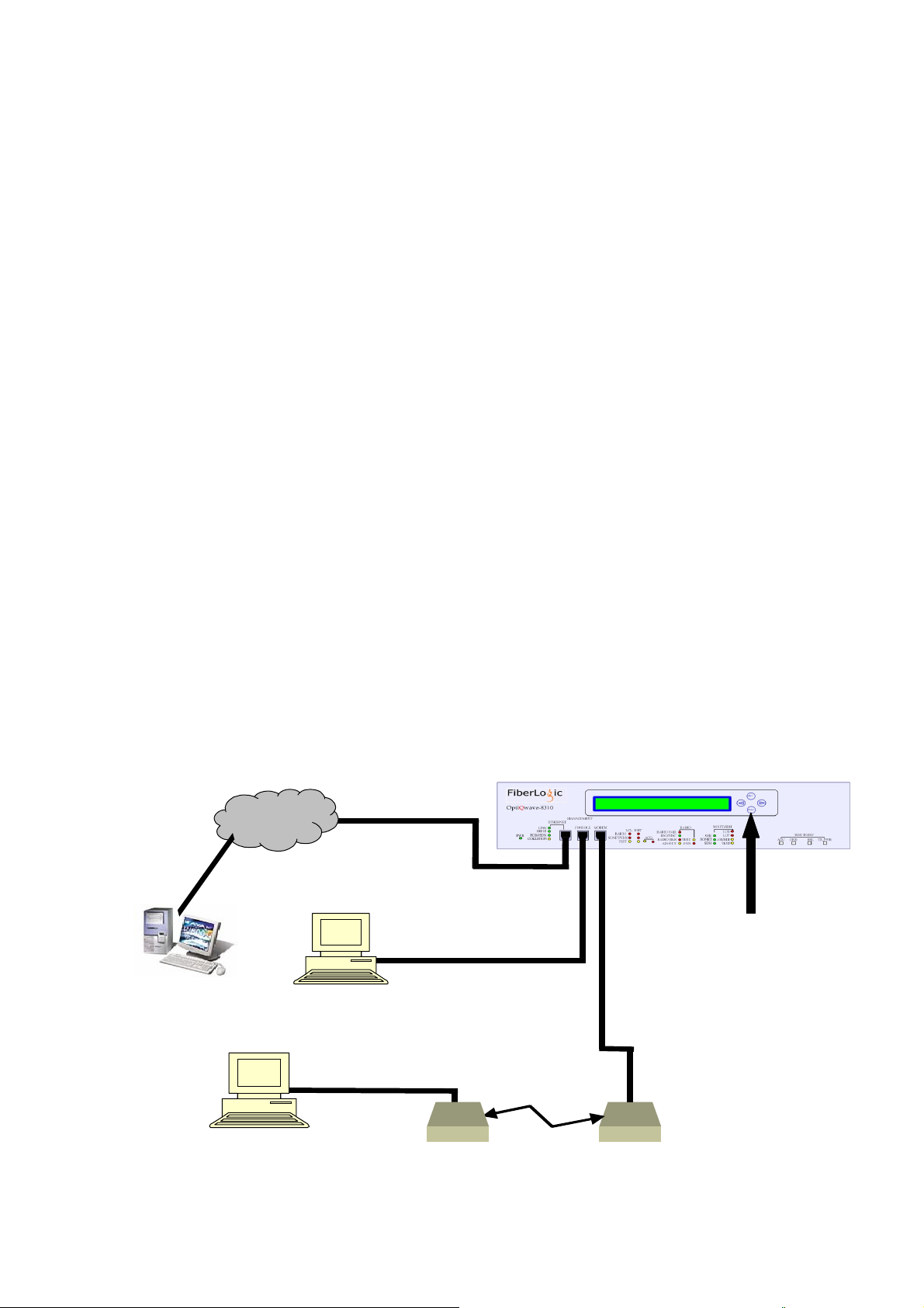
5.3 System Mangement
OptiQwave-8310 SDH STM-1 Digital Microwave porivdes the following interface: Ethernet Port,
Console Port, Modem Port, Remote RS232 Port and LCD panel. Via the interfaces above, system
management for local and remote can be done.
LCD Interface
Use ←, →, Enter and ESC control keys located at the front panel to configure the system. Both
LOCAL and REMOTE units can be configured via LCD interface. System functions such as
configuration, monitoring, view, and loopbacks can be performed for both LOCAL and REMOTE
units.
CID (Craft Interface Device, Console) Interface
The CID interface is RJ45, the standard EIA RS232C controlling signal. By connecting VT-100
via the CID interface, system Menu Tree can be accessed. You can configure, monitor, view,
perform loopback, and other system functions for both Local and Remote units via the CID
interface
Modem Interface
The MODEM interface is RJ45, the standard EIA RS232C controlling signal. User can connect to
the remote VT-100 terminal via modem dialup. Remote unit can be accessed locally through the
independent EOC channel. You can configure, monitor, view, perform loopback, and other system
functions for both Local and Remote units via the MODEM interface.
ASCII
Terminal
Ethernet
Cable
(RJ45 to RJ45)
DTE
Local Console
Modem
DCE
ASCII
Terminal
DTE
RS
-
232 Modem Cable
(
DB9F to DB9M)
Modem
DCE
Internet
RS
-
232 Console Cable
(
DB9F to RJ45)
OptiQwave -8310
LCD W/ Key Control
(Telnet, SNMP, GUI)
PSTN
Leased line or dial up
(9600,8.n,1)
DTE
Figure 5.1
RS
-
232 Modem Cable
(
(DB9M to
RJ45)
(9600,8.n,1
)

10
Ethernet Interface
The 100/10Base T interface is RJ45 female. It conforms to IEEE802.3. LED indications
including LINK, 100/10, FDX/HDX, and COLLISION are located at the front panel. System
configurations, monitoring, system status, loopbacks and other system functions can be performed
via the Ethernet interface, telnet, SNMP and FiberLogic GUI interface. See below:
155.52
Mbps
Figure 5.2 Ethernet Back-to-Back Connection
LAN/Internet
Remote Management
Telnet
SNMP
GUI
IP1
Cross
-
Ove
IP3
Note: local and remote system can be managed via IP1, IP2,
IP3…and etc.
Note: Bridge functionality will only be effective when both
sides are activated. (Bridge : On) Please note that not
to connect the path for radio, ethernet and bridge into a
ring or the Ethernet packets will be in loops.
155.52
Mbps
OptiQwave
8310
Ethernet
OptiQwave
8310
Ethernet
OptiQwave
8310
Ethernet
OptiQwave
8310
Ethernet
OptiQwave
8310
Ethernet
OptiQwave
8310
Ethernet
Cross
-
Ove
IP2
155.52
Mbps
155.52
Mbps

11
R-RS232 (Remote RS-232) Interface
The connector is RJ45 female. It is the standard EIA RS232C controlling signal. It can be
connected to the local VT-100 terminal. Menu Driven tree can be accessed and therefore system
configurations can be performed. The configuring data are transmitted via the independent EOC
channel, and therefore does not take up other system resources.
5.4 Orderwire Interface
The connector is RJ11 Female. It can be connected to handset or headset (2-line). It is useful for
personnel communications inbetween the microwave links.
5.5 Alarm Output Relay
The connector is DB9 Female.
Audible RADIO Alarm (AR) Normal Open
Visual RADIO Alarm (VR) Normal Open
Audible SONET/SDH LINE Alarm (AL) Normal Open
Visual SONET/SDH LINE Alarm (VL) Normal Open
Common Ground (C) Common GND
Figure 5.3 RS-232 Connection
155.52
Mbps
COM1 COM2
VT100 Terminal
Remote microwave chain
Local microwave chain
COM1 Control Local
COM2 Control Remote
155.52
Mbps
155.52
Mbps
OptiQwave
8310
CID
R
-
RS232
OptiQwave
8310
CID
R
-
RS232
OptiQwave
8310
CID
R
-
RS232
OptiQwave
8310
CID
R
-
RS232

12
5.6 System Functionalities
Maintenance and performance monitoring can be performed via LCD, CID, Telnet, and FiberLogic
GUI, operated on PC Windows 98TM and above OS.
System Menu Tree LOCAL
REMOTE
System Configuration and System Description ○△
SNMP Configuration ○○
MODEM Configuration ○○
User/Password Configuration ○×
System Rest (RST) ○○
Radio Interface Configuration and Status ○△
SONET/SDH Configuration and Status Checking ○○
TPL Configuration & RF Signal Checking ○○
Radio Loopback and Release ○×
SONET/SDH Loopback and Release ○○
PRBS Enable and Release ○○
1-hour Performance Report at 15-min Interval for SONET/SDH ○○
1-day Performance Report at 15-min Interval for SONET/SDH ○○
7-day Performance Report at 24-hr Interval for SONET/SDH ○○
Clear History and Report ○○
ES SES B1BER Threshold Settings in 15 Minutes for SONET/SDH Interface
○○
ES SES B1BER Threshold Settings in 1 Hour for SONET/SDH Interface ○○
ES SES B1BER Threshold Settings in 1 Day for SONET/SDH Interface ○○
View Radio Interface Alarm ○○
View SONET/SDH Interface Alarm ○○
View Alarm History ○○
Clear Alarm History ○○
○: executable x: not executable △: partial executable
Note:
The Frequency Plan and the remote log in user/password cannot be altered from the local
system.
The remote RADIO baseband loopback cannot be activated from local.
The remote RADIO security code cannot be altered from the local LCD; however, it can
be altered via other interfaces locally.

13
5.7 LED Status Indication
System Power
Ethernet
Link
Speed (100/10)
Full Duplex/Half Duplex (FDX/HDX)
Collision (COLLISION)
Alarm Suppress (ACO) Key
System Status LED
LCL (Local) for Radio Alarm, SONET/SDH Alarm and Test
RMT (Remote) for Radio, SONET/SDH Alarm and Test
Radio Interface LED
RADIO Fail (RADIO FAIL), RADIO Synchronization (RX SYNC)
RADIO Bit Rate Error (RADIO BER), AIS Out (AIS OUT),
Test (TEST), FAN (FAN)
SONET/SDH Interface LED
O/E, SONET
SDH, LOS
LOF, AIS/RDI
TEST
5.8 Test Point
TX_PWR, AGC, GND, RSL
SONET/SDH
SONET/SDHSONET/SDH
SONET/SDH
O/E
O/EO/E
O/E
SONET
SONETSONET
SONET
SD
SDSD
SDH
HH
H
LOS
LOSLOS
LOS
LOF
LOFLOF
LOF
AIS/RDI
AIS/RDIAIS/RDI
AIS/RDI
TEST
TESTTEST
TEST
RADIO
RADIORADIO
RADIO
RADIO
RADIO RADIO
RADIO
FAIL
FAILFAIL
FAIL
RX SYNC
RX SYNCRX SYNC
RX SYNC
RADIO BER
RADIO BERRADIO BER
RADIO BER
AIS OUT
AIS OUTAIS OUT
AIS OUT
TEST
TESTTEST
TEST
FAN
FANFAN
FAN
RADIO
RADIORADIO
RADIO
SONET/SDH
SONET/SDHSONET/SDH
SONET/SDH
TEST
TESTTEST
TEST
LCL
LCLLCL
LCL
RMT
RMT RMT
RMT
RSL
TX_PWR
TEST POINT
GND
AGC

14
5.9 Power Supply
AC 90~240V or 47Hz to 63Hz
DC -36 ~-72V
Connector Type AC: AC Plug
DC: secured with screws
Power consumption ≦60 Watts
5.10 Operation Temperature
Temperature:0~50℃.
Humidity:5 %~95%, non-condensing.
5.11 Dimension
W445mm x D326mm x H88mm
The unit is desktop stackable and 19- or 23- inch rack mountable.
5.12 EMI
Conforms to FCC Part15, Subpart B, Class B; CISPR22 Class B.
5.13 MTBF (Mean Time Between Failure)
MTBF is greater than 45,000 hours.

15
Chapter 6
6. System Installation & Test
The OptiQwave-8310 SDH STM-1 DIGITAL MICROWAVE is indoor equipment. It can be
placed at desktop or rack-mounted on 19” or 23” rack.
6.1 Power
The system uses dual power module, AC and DC with auto-switching mechanism.
Please see Figure 6.1 for DC pins definition. See Figure 6.2 for AC pins definition.
Note: When installing the power to the unit, please make sure the switch is at the OFF position.
When using DC power, please take off the fuse at the fuse panel. Restore the fuse back
after the power installation is finished.
Note: When applying the power to the unit, please make sure the antenna or 50Ωterminal
resistance or RF power meter is attached to the RF interface so that the transmitter will not
be damaged.
6.2 Antenna Installation
SDH STM-1 DIGITAL MICROWAVE is used in point-to-point; therefore, it has to be used in
pairs (with opposite transmitting and receiving frequencies). The antenna has to be in the line of
sight, shown as figure 6.3. Therefore, it is recommended to fix the antenna at tower, roof, or open
spaces to ensure better transmission. It is recommended to use antenna with radius of 1 inch at
least. The antenna has to be grounded to avoid lightening or any electrical shortage.
F
i
R
e
-
F
r
F
G
F
1
1
AC 100-240V
50-60Hz
Table of contents


