Fibrenetix Mobix-II Series Instruction manual

Manual 130120
2:69 Mobix-II Series
Contents 1:3
Disclaimer ............................................................................................................................................................................... 5
Safety Precautions.......................................................................................................................................................... 5
Introduction ....................................................................................................................................................................... 6
Key Features.............................................................................................................................................................................6
Hardware Specication................................................................................................................................................7
Hardware Details............................................................................................................................................................. 9
Mobix-II (RJ45) ........................................................................................................................................................................9
Front Panel ............................................................................................................................................................ 9
Rear Panel ........................................................................................................................................................... 10
Mobix-II (M12) .......................................................................................................................................................................11
Front Panel ......................................................................................................................................................... 11
Rear Panel ........................................................................................................................................................... 12
Mechanical Dimensions........................................................................................................................................... 13
Mobix-II (RJ45) / Mobix-II (M12) ..................................................................................................................................... 13
Europe Americas
Quick User Guide
Mobix-II Series
Superior Fan less Embedded System
Mobix-II Series
MB-502-5-5000-A2-CT
MB-506-5-7600-A2-CT
MB-510-5-7600-A2-CT
MB-506-5-7600-A12-CT
MB-510-5-7600 -A12-CT MB-502-5-5000-A2-CT
User Guide

Manual 130120
3:69 Mobix-II Series
Contents 2:3
Switches and Connectors......................................................................................................................................... 14
Switch and Connector Locations................................................................................................................................. 14
............................................................................................................................................................... 14
........................................................................................................................................................ 15
List of Connectors / Switches ....................................................................................................................................... 16
Switches Denitions ......................................................................................................................................................... 17
Connectors Denitions.................................................................................................................................................... 17
System Setup ................................................................................................................................................................... 33
Installing HDD on removable SATA HDD bay ......................................................................................................... 33
Installing SIM card ............................................................................................................................................................. 34
Installing wall mount Kit ................................................................................................................................................. 36
BIOS Introduction.......................................................................................................................................................... 37
Main Menu ............................................................................................................................................................................ 37
General Help <F1>............................................................................................................................................................... 37
Main Setup ............................................................................................................................................................................ 38
System Language .............................................................................................................................................. 38
System Date ........................................................................................................................................................ 38
System Time ....................................................................................................................................................... 38
Advanced Setup.................................................................................................................................................................. 39
..............................................................................................................................................40
...................................................................................................................................... 41
............................................................................................................................ 42
Trusted Computing ............................................................................................................................................43
ACPI Settings........................................................................................................................................................ 43
...............................................................................................................44
NCT6106D HW Monitor .................................................................................................................................... 49
Serial Port Console Redirection .................................................................................................................... 50
.......................................................................................................................... 51
............................................................................................................................................. 52
..............................................................................................................................................54
Europe Americas
User Guide

Manual 130120
4:69 Mobix-II Series
Contents 3:3
Chipset ................................................................................................................................................................................. 55
...................................................................................................................56
........................................................................................................................................ 59
Security ................................................................................................................................................................................. 63
...................................................................................................................................63
....................................................................................................................................................63
Boot .................................................................................................................................................................................64
Setup Prompt Timeout .....................................................................................................................................64
.....................................................................................................................................64
......................................................................................................................................64
Hard Driver BBS Priorities................................................................................................................................64
Save & Exit ............................................................................................................................................................................65
Save Changes and Reset ..................................................................................................................................65
Discard Changes and Reset.............................................................................................................................65
Restore Defaults .................................................................................................................................................65
Watch Dog Timer (WDT) & General-Purpose Input / Output (GPIO) ........................................66
WDT Sample Code...............................................................................................................................................................66
GPIO Sample Code.............................................................................................................................................................. 67
Point of Contact ................................................................................................................................................................66
Europe Americas
User Guide

Manual 130120
5:69 Mobix-II Series
Europe Americas
Disclaimer
Published January 2020
Copyright and Trademarks
Copyright © 2019 Fibrenetix Aps or its subsidiaries. All rights reserved.
DO NOT dispose this electronic device into the trash while discarding.
Please recycle to minimize pollution and ensure environment protection.
Safety Precautions
Before installing and using the equipment, please read the following precautions:
1. Place the equipment on a reliable surface during installation. Dropping it or letting it fall could cause damage.
2. The power outlet shall be installed near the equipment and shall be easily accessible.
3. Turn off the system power and disconnect the power cord from its source before making any installation.
Be sure both the system and the external devices are turned OFF. Sudden surge of power could ruin sensitive components.
Make sure the equipment is properly grounded.
4. When the power is connected, never open the equipment. The equipment should be opened only by qualified service
personnel.
5. Make sure the voltage of the power source is correct before connecting the equipment to the power outlet.
6. Disconnect this equipment from the power before cleaning. Use a damp cloth. Do not use liquid or spray detergents
for cleaning.
7. Avoid the dusty, humidity and temperature extremes.
8. Do not place heavy objects on the equipment.
9. If the equipment is not used for long time, disconnect it from the power to avoid being damaged by transient over-voltage.
10. The storage temperature shall be above -30°C and below 85°C.
11. The computer is provided with a battery-powered real-time clock circuit. There is a danger of explosion if incorrectly
replaced. Replace only with the same or equivalent type recommended by the manufacturer.
12. If one of the following situations arises, get the equipment checked be service personnel:
■ The power cord or plug is damaged.
■ Liquid has penetrated the equipment.
■ The equipment has been exposed to moisture.
■ The equipment does not work well, or it cannot work according the user’s manual.
■ The equipment has been dropped and damaged.
■ The equipment has obvious signs of breakage.
User Guide

Manual 130120
6:69 Mobix-II Series
Europe Americas
Introduction
Mobix-II series – Superior Fan less Embedded System
-
-
applications.
Key Features:
■ LGA 1151 socket for 6th/7th Gen. Intel® Core™ i7/i5/i3 or Pentium® / Celeron® Desktop Processor
■ Intel® Q170 Chipset
■ 2x 260-pin DDR4 SODIMM. Max up to 32GB
■ Triple independent display supported by 1x DVI-I and 2x DisplayPort
■ 2x Intel® GbE supporting Wake-on-LAN and PXE
■ 2x Removable 2.5” SATA HDD Bay, 2x Internal 2.5” SATA SSD/HDD Bay supporting RAID 0, 1, 5, 10
■ 4x Full-size Mini-PCIe Socket with 4x SIM Card Socket for communication or expansion modules
■ 2x mSATA (Shared by 2x Mini-PCIe Socket)
■ 2x External RS-232/422/485, 2x Internal RS-232/422/485
■ 6x USB 3.0, 2x USB 2.0, TPM 1.2
■ 8x Isolated DI, 8x Isolated DO
■ 1x Mic-in, 1x Speak-out
■ 9 to 48VDC wide range power input supporting AT/ATX mode
■ 1x PCIe x16 Expansion (RCO-6011E Series Only)
■ 1x PCI Expansion (RCO-6011P Series Only)
■ 2x PCIe x8 Expansion (RCO-6022EE Series Only)
■ 2x PCI Expansion (RCO-6022PP Series Only)
■ 1x PCIe x16 and 1x PCI Expansion (RCO-6022PE Series Only)
■ Remote Power On/Off Switch
User Guide

Manual 130120
7:69 Mobix-II Series
Europe Americas
Hardware Specication 1:2
*Specications are subject to change, without prior notice.
System MOBIX-II Series - MB-5XX-X-XXX-AXX-CT
Processor Intel®Core®®Processor
Core Logic Intel®Q170 Express Chipset
Memory
Max. up to 32GB
OS Storage (internal 2.5”) 2x Internal 2.5” SATA HDD Bay
2x Removable 2.5” SATA HDD Bay
Hardware RAID Levels
Network (Model MB-502-X-XXX-A2-CT) GbE1: Intel®
GbE2: Intel®
Network (Model MB-506-X-XXX-A2-CT)
and (Model MB-506-X-XXX-A12-CT)
GbE1: Intel®
GbE2: Intel®
GbE3 to GbE6: Intel®I350-AM4
Multiple Display 1x DVI-I
2x DisplayPort
VGA through optional split cable
Audio Codec
SIM Socket
Multi-Constellation GNSS
LTE Category 4 Module Data Transfer
DC-HSDPA : Max 42Mbps (DL)
HSUPA : Max 5.76Mbps (UL)
LTE Module Protocols
I/O Ports
2x GbE RJ45 (all models)
6x Wi-Fi Antenna Holes
Operating System
Power Ignition Management Yes (except for MB-502)
Power Adaptor
Voltage 9 to 48 VDC
Dimensions – mm (D x W x H) 261 x 240 x 79
Environment
Relative Humidity (%)
User Guide

Manual 130120
8:69 Mobix-II Series
Europe Americas
Hardware Specication 2:2
*Specications are subject to change, without prior notice.
Vibration
Shock
Certication
Warranty Period 3 Years
BTU/hr (with optional Power Adaptor) 410.31
User Guide

Manual 130120
9:69 Mobix-II Series
Europe Americas
Hardware Details
Mobix-II (RJ45)
Front Panel
ATX power on/o switch
Reset switch
Press to reset the system
USB 3.0 port
USB 2.0 port
AT/ATX mode select switch
Clear CMOS
Used to clear CMOS
SIM card
Used to insert SIM card
COM port
LAN Port
(MobixII-4L Only)
POE Port
over Ethernet (MobixII-4P Only)
Universal I/O Bracket
HDD port
Removable 2.5” SATA HDD Area
Power LED
HDD LED
Indicates the status of the hard drive
Watchdog LED
GPIO LED
Ethernet LEDs
Indicates the status of the LAN active
Antenna hole
Used to connect an antenna for optional
Mini-PCIe WiFi module
User Guide

Manual 130120
10:69 Mobix-II Series
Europe Americas
Hardware Details
Mobix-II (RJ45)
Rear Panel
DC IN
Speaker-out
Mic-in
Used to connect a microphone
Digital I/O Terminal Block
and 8 digital output
COM port
DVI-I port
Used to connect a DVI monitor or connect
optional split cable for dual display mode
Display Port
Used to connect a DisplayPort monitor
USB 3.0 port
LAN port
Remote Power on/o Terminal Block
Antenna hole
Used to connect an antenna for optional Mini-PCIe WiFi module
User Guide

Manual 130120
11:69 Mobix-II Series
Europe Americas
M12 PoE Port
over Ethernet (MobixII-4P-M12 Only)
Universal I/O Bracket
HDD port
Removable 2.5” SATA HDD Area
Power LED
HDD LED
Indicates the status of the hard drive
Watchdog LED
GPIO LED
Ethernet LEDs
Indicates the status of the LAN active
Antenna hole
Used to connect an antenna for optional
Mini-PCIe WiFi module
Hardware Details
Mobix-II (M12)
Front Panel
ATX power on/o switch
Reset switch
Press to reset the system
USB 3.0 port
USB 2.0 port
AT/ATX mode select switch
Clear CMOS
Used to clear CMOS
SIM card
Used to insert SIM card
COM port
LAN Port
(MobixII-4L-M12 Only)
User Guide

Manual 130120
12:69 Mobix-II Series
Europe Americas
Hardware Details
Mobix-II (M12)
Rear Panel
DC IN
Speaker-out
Mic-in
Used to connect a microphone
Digital I/O Terminal Block
and 8 digital output
COM port
DVI-I port
Used to connect a DVI monitor or connect
optional split cable for dual display mode
Display Port
Used to connect a DisplayPort monitor
USB 3.0 port
LAN port
Remote Power on/o Terminal Block
Antenna hole
Used to connect an antenna for optional Mini-PCIe WiFi module
User Guide

Manual 130120
13:69 Mobix-II Series
Europe Americas
Mechanical Dimensions
Mobix-II (RJ45) / Mobix-II (M12)
User Guide

Manual 130120
16:69 Mobix-II Series
Europe Americas
List of Connectors / Switches
Explanation for page 14 and page 15
Connector Location Denition
AT_ATX1
CLR_CMOS1
PWR_SW1
RESET1
USB3_1, USB3_2 USB 3.0 Port
USB2_1, USB2_2 USB 2.0 Port
USB2_CN1 USB 2.0 Port
SIM1, SIM2, SIM3, SIM4
COM1_2_1
COM3_1, COM4_1
DC_IN1
DVI_I1 DVI-I Connector
DP1, DP2 DisplayPort Connector
SPK_OUT1
MIC_IN1
DIO1
PWR_SW2
CN1 LAN1 and USB3.0 Port
CN2 LAN2 and USB3.0 Port
LAN3, LAN4, LAN5, LAN6, LAN7, LAN8, LAN9, LAN10
MINIPCIE1, MINIPCIE2
CN3, CN4
SATA1, SATA2, SATA3, SATA4
POWER1, POWER2, POWER3, POWER4
PCIE1
PCIE2
PWR_LED1
HDD_LED1 HDD Access LED Status
WDT_LED1 Watchdog LED Status
GPIO_LED1 GPIO LED Status
LAN1_LINK1, LAN2_LINK1
LAN1_ACT1, LAN2_ACT1 LAN Active LED
User Guide

Manual 130120
17:69 Mobix-II Series
Europe Americas
Switch Denition
1–2 (Left)
2–3 (Right)
Switch Denition
O Normal Status (Default)
ON Clear BIOS
Switches Denitions
AT_ATX1: AT / ATX Power Mode Switch
CLR_CMOS1: Clear BIOS Switch ON
1
RightLeft
Connectors Denitions
PWR_SW1: Power Button
RESET1 : Reset Button
USB3_1: USB3.0 Connector, Type A
Pin Denition Pin Denition
1NC 4GND
2 5NC
3NC 6GND
Pin Denition Pin Denition
1 6
2 7GND
3 8
4GND 9
5
Pin Denition
1RESET
2GND
User Guide

Manual 130120
18:69 Mobix-II Series
Europe Americas
Connectors Denitions
USB3_2: USB3.0 Connector, Type A
USB2_1: USB3.0 Connector, Type A
USB2_2: USB3.0 Connector, Type A
USB2_CN1: USB2.0 Ports
Connector Type: 2X5 10-pin box header, 2.0mm pitch
Pin Denition Pin Denition
1 6
2 7GND
3 8
4GND 9
5
Pin Denition Pin Denition
1 2
3 4
5 6
7GND 8GND
9Cable Shield 10 Cable Shield
Pin Denition
1
2
3
4GND
Pin Denition
1
2
3
4GND
10
9
2
1
User Guide

Manual 130120
19:69 Mobix-II Series
Europe Americas
Connectors Denitions
SIM1: SIM Card Socket
SIM2: SIM Card Socket
SIM3: SIM Card Socket
SIM4: SIM Card Socket
Pin Denition Pin Denition
C1 UIM1_PWR C6 UIM1_VPP
C2 UIM1_RESET C7 UIM1_DATA
C3 UIM1_CLK CD NC
C5 GND COM GND
Pin Denition Pin Denition
C1 UIM2_PWR C6 UIM2_VPP
C2 UIM2_RESET C7 UIM2_DATA
C3 UIM2_CLK CD NC
C5 GND COM GND
Pin Denition Pin Denition
C1 UIM3_PWR C5 GND
C2 UIM3_RESET C6 UIM3_VPP
C3 UIM3_CLK C7 UIM3_DATA
Pin Denition Pin Denition
C1 UIM4_PWR C5 GND
C2 UIM4_RESET C6 UIM4_VPP
C3 UIM4_CLK C7 UIM4_DATA
User Guide

Manual 130120
20:69 Mobix-II Series
Europe Americas
Connectors Denitions
COM1_2_1: RS232 / RS422 / RS485 Connector
Connector Type: 9-pin D-Sub
COM3_1: RS232 / RS422 / RS485 Connector
Connector Type: 2X5 10-pin box header, 2.54mm pitch
COM1
Pin RS232 Denition RS422 / 485 Full Duplex
Denition
RS485 Half Duplex
Denition
1DCD1
2RxD1
3TxD1
4DTR1
5GND
6DSR1
7RTS1
8CTS1
9RI1
COM3_1
Pin RS232 Denition RS422 / 485 Ful Duplex
Denition
RS485 Half Duplex
Denition
1DCD3
2RxD3
3TxD3
4DTR3
5GND
6DSR3
7RTS3
8CTS3
9RI3
COM2
Pin RS232 Denition RS422 / 485 Full Duplex
Denition
RS485 Half Duplex
Denition
10 DCD2
11 RxD2
12 TxD2
13 DTR2
14 GND
15 DSR2
16 RTS2
17 CTS2
18 RI2
10
9
2
1
10
1
15
6
14
5
18
9
User Guide
This manual suits for next models
5
Table of contents
Popular Desktop manuals by other brands

HP
HP Pavilion v300 - Desktop PC user guide

Sony
Sony VAIO VGN-FW Series Operating instructions - hardware guide
Moxa Technologies
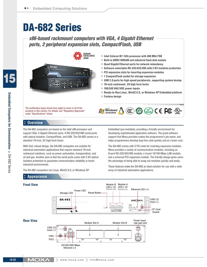
Moxa Technologies DA-682 Series Brochure & specs

IBM
IBM NetVista A20 quick reference

Lenovo
Lenovo ThinkCentre M70z Vodič za uporabnika

IEI Technology
IEI Technology MODAT-532A user manual


