Fike 10-2528 User manual
INSTALLATIONINSTRUCTIONS
Doc.No.06‐479● Rev.3,March2019
ISO9001:2015Certified
Page1of5
DIGITALALARMCOMMUNICATORTRANSMITTER(DACT)MODULEKIT(P/N10‐2528)
ImportantNoticesBeforeYouBegin
1. Pleasereadtheinstructionscarefully!Fikeproductsare
usedfortheprotectionoflifeandcriticalassetsand
mustbeinstalledandtestedasdescribedinthis
document.
2. DonotuseFikeproductsforanyapplicationforwhich
theyarenotintended.Fikeshallnotbeinanywayliable
foranydamagesorlossesincurredbyyouorthird
partiesarisingfromtheuseofanyFikeproductfor
whichtheproductisnotintendedbyFike.
3. DonotuseFikeproductsdescribedinthisdocument
outsideoftherangesspecifiedbyFike.Fikeshallhave
noliabilityformalfunctionsordamagesarisingoutof
theuseofFikeproductsbeyondsuchspecifiedranges.
4. Fikereservestherighttochangeproductdesignsor
specificationswithoutobligationandfurthernotice.
5. ThisdocumentissubjecttotheFikefulldisclaimerat
http://www.fike.com/disclaimer.
6. Visitwww.fike.comtocontactusortodownloadthe
latestversionofthisdocument.
ImportantSafetyNotes
Thefollowingformatsareusedforsafetynotesinthese
instructions.
WARNING
Thistypeofnoteisusedtoindicatethepresenceofa
hazardthatwillormaycausepersonalinjuryordeathor
lossofserviceifsafetyinstructionsarenotfollowedorif
thehazardisnotavoided.
CAUTION
Thistypeofnoteindicatesthepresenceofahazardthat
willormaycausedamagetotheequipmentifsafety
instructionsarenotfollowedorifthehazardisnot
avoided.
NOTE
Indicatesthemessageisimportant,butnotofawarning
orcautioncategory.Thesenotescanbeofgreatbenefitto
theuserandshouldberead.
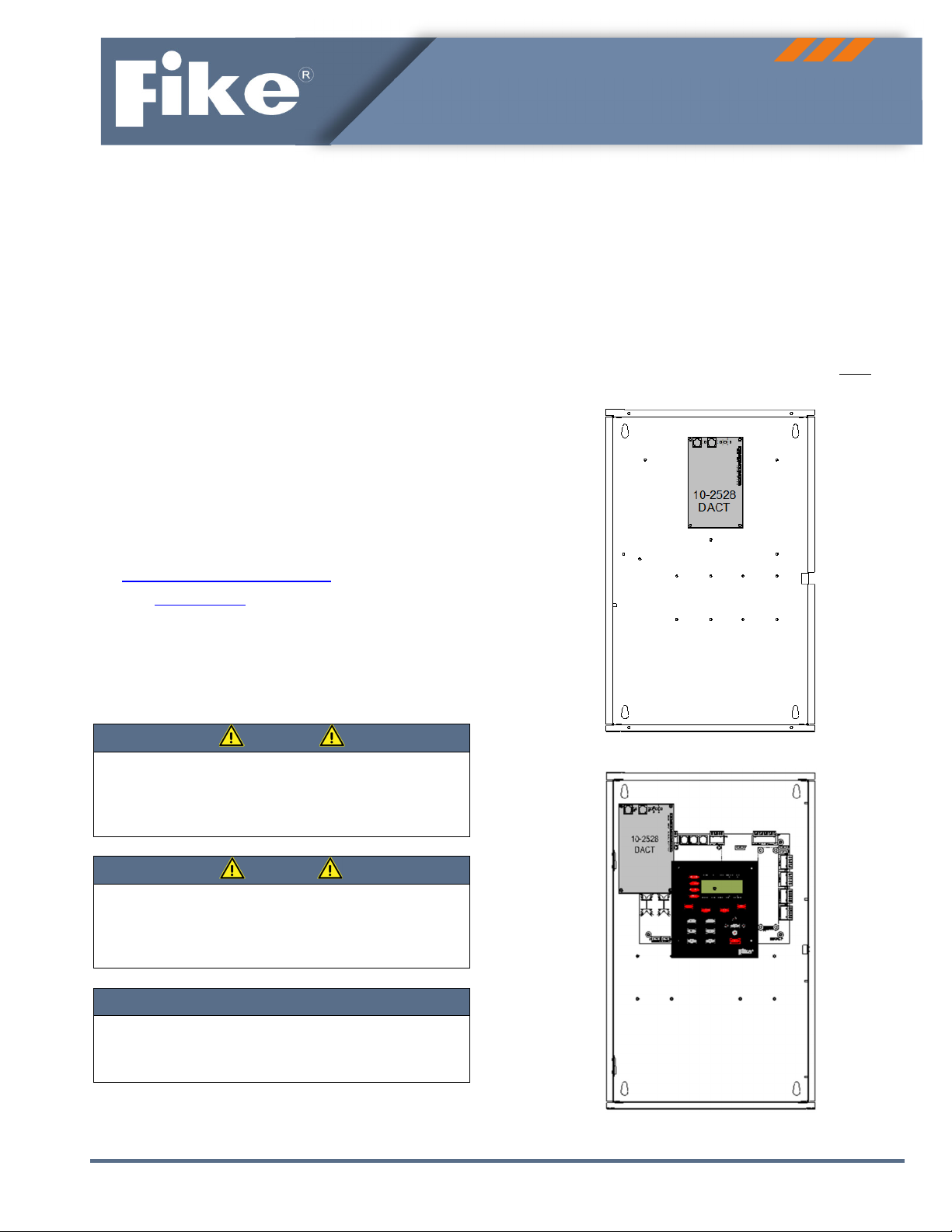
MountingLocation
TheDACTmountinglocationvariesdependinguponthe
controlpanelenclosureitistobeinstalledinto.Theimages
belowshowtheappropriateDACTmountinglocationsfor
eachcompatiblecontrolpanelenclosure.
IMPORTANT!WheninstallingtheDACTintheCyberCat™
50orCheetah™Xi50enclosures,theDACTmustbe
installedbeforethecontrolboard.
DACTMountingforCyberCat™50orCheetah™Xi50
DACTMountingforCyberCat™254/1016orCheetah™Xi
Page2of5
ISO9001:2015CertifiedDoc.No.06‐479● Rev.3,March2019
Installation
Installationandwiringshouldbeperformedbyqualified
personnelonly.Equipmentdamageand/ormalfunction
mayresultfromimproperinstallation.Disableallcritical
systemfunctionsandremoveallpowerfromthesystem
untiltheinstallationiscompleteandreadyfortesting.
CAUTION
TheDACTcircuitboardcontainsstatic‐sensitive
components.Handletheelectronicsbytheedgesonly
andavoidtouchingtheintegratedcomponents.Keep
electronicsintheprotectivestaticbagitwasshippedin
untiltimeforinstallation.Alwaysgroundyourselfwitha
properwriststrapbeforehandlingthemodule(s).Ifthe
installerisproperlygroundedatalltimes,damagedueto
staticdischargewillnotoccur.Ifthemodulerequires
repairorreturntoFike,itmustbeshippedinananti‐
staticbag.
TheDACTisinstalledontothethreadedpressstuds
providedinthebackoftheenclosureusingthe
following
mountinghardwaresuppliedwiththecard.
StandoffHardwareKit,P/N02‐12037,includes:
02‐117516‐32hex.Standoff,2”long,F/F
(CyberCat™254/1016andCheetah™Xi)
02‐118336‐32hex.Standoff,5/8”long,F/F
(CyberCat™50andCheetah™Xi50)
02‐15896‐32x.375Phillipspanheadscrew,zinc
plated(CyberCat™50andCheetah™Xi50)
02‐168706‐32hex,Standoff3/8”long,M/F
(CyberCat™254/1016andCheetah™Xi)
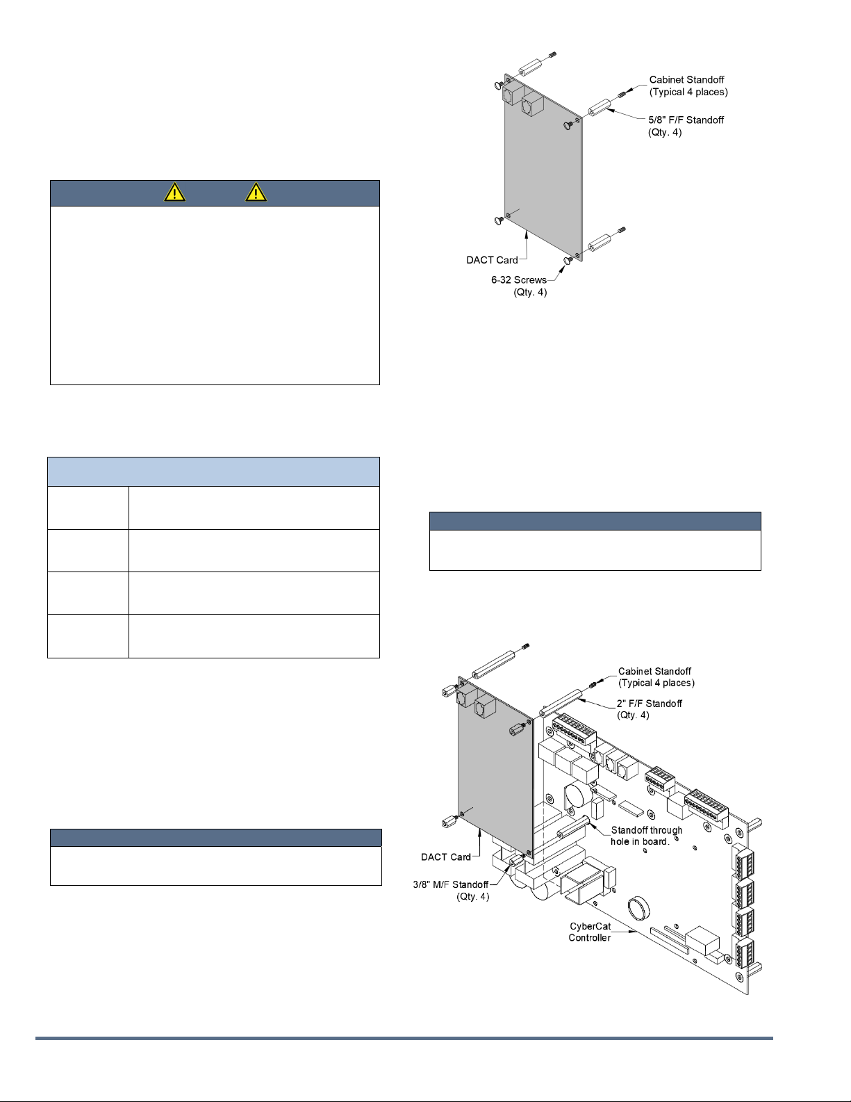
ToinstalltheDACTintotheCyberCat™50orCheetah™Xi
50systemenclosures:
1. CarefullyunpacktheDACTandcheckforshipping
damage.
2. Securethefour.625”F/Fstandoffs(P/N02‐11833)onto
thethreadedpressstudsonthebackoftheenclosure,
asshownintheimagebelow.
NOTE
FortheCyberCat™50orCheetah™Xi50,installthe
DACT,theninstallthesystemcontrolboard.
3. InstalltheDACTontothestandoffsandsecureitin
placebythreadingthefour6‐32”screws(P/N02‐1589)
throughtheboardandintothestandoffs.
DACTMountingforCyberCat™50orCheetah™Xi50
ToinstalltheDACTintotheCyberCat™254/1016or
Cheetah™Xisystemenclosures:
1. CarefullyunpacktheDACTandcheckforshipping
damage.
2. Securethefour2”F/Fstandoffs(P/N02‐11751)onto
thethreadedpressstudsonthebackoftheenclosure,
asshownatright.Thelower‐rightstandoffmustbe
installedthroughthemountingholeprovidedinthe
systemcontrolboard.
NOTE
FortheCyberCat™254/1016andCheetah™Xi,install
thesystemcontrolboard,theninstalltheDACT.
3. InstalltheDACTontothestandoffsandsecureitin
placebythreadingthefour3/8”standoffsthroughthe
DACTboardandintothe2”standoffs.
DACTMountingforCyberCat™254/1016orCheetah™Xi
Doc.No.06‐479● Rev.3,March2019ISO9001:2015CertifiedPage3of5
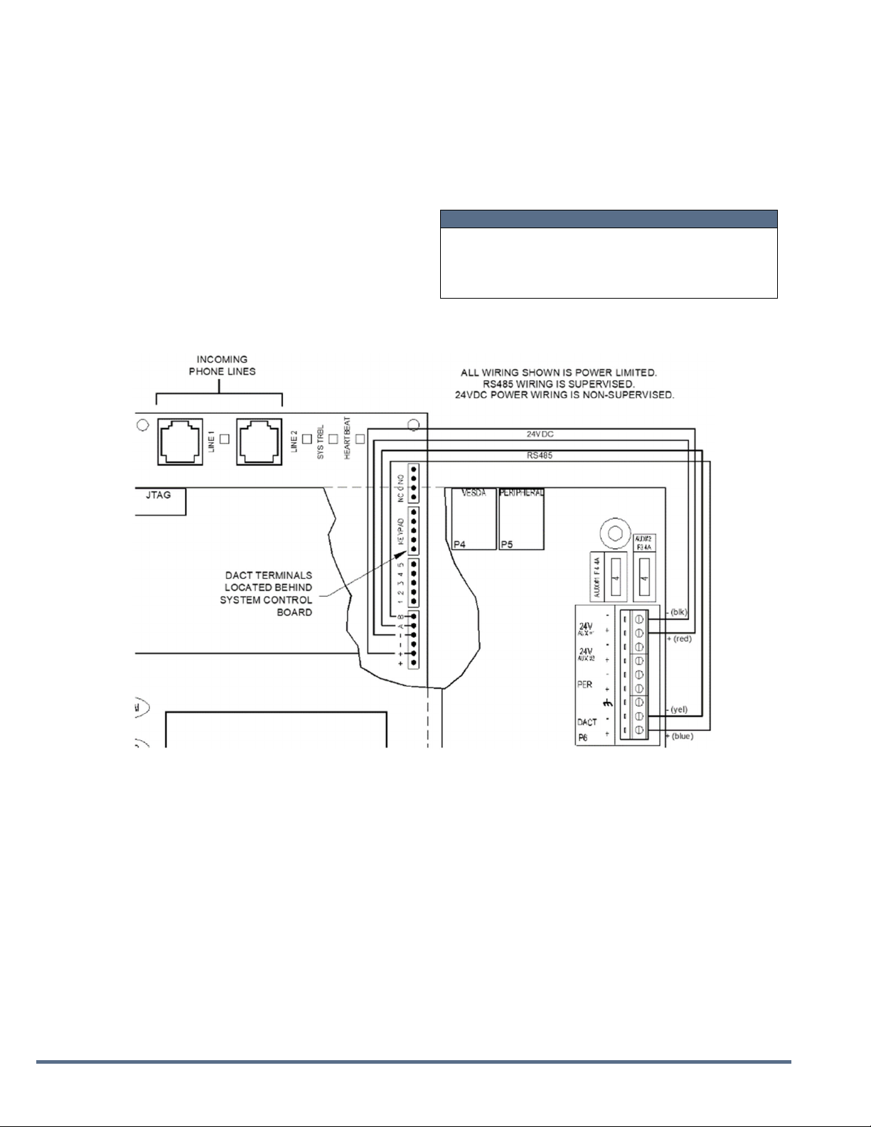
DACTWiring:CyberCat™254/1016andCheetah™Xi
Thewiringdiagrambelowshowshowtoelectricallyconnect
theDACTintotheCyberCat™andCheetah™Xipanels.
1. Installwiringtoconnect24VDCcontinuouspowerfrom
thesystemcontroller(TerminalP7,Aux.Output,+/‐)to
theDACT,asshownbelow.
2. Apply24VDCpowertotheDACTandprogramusingthe
10‐2477five‐zonehand‐heldDACTprogrammer.
3. InstallRS485wiringfromthesystemcontroller(terminal
P6)totheDACT(‐toA;+toB),asshownbelow.
4. Connectincomingphonelinesandtestforproper
operation.
NOTE
WhentheDACTmoduleisinstalled,theincomingphone
lines(power‐limited)mustberoutedseparatelyfrom
anynon‐power‐limitedrelayconnectionstothesystem
controller.
DACTWiring:CyberCat™254/1016andCheetahXi™
Page4of5
ISO9001:2015CertifiedDoc.No.06‐479● Rev.3,March2019
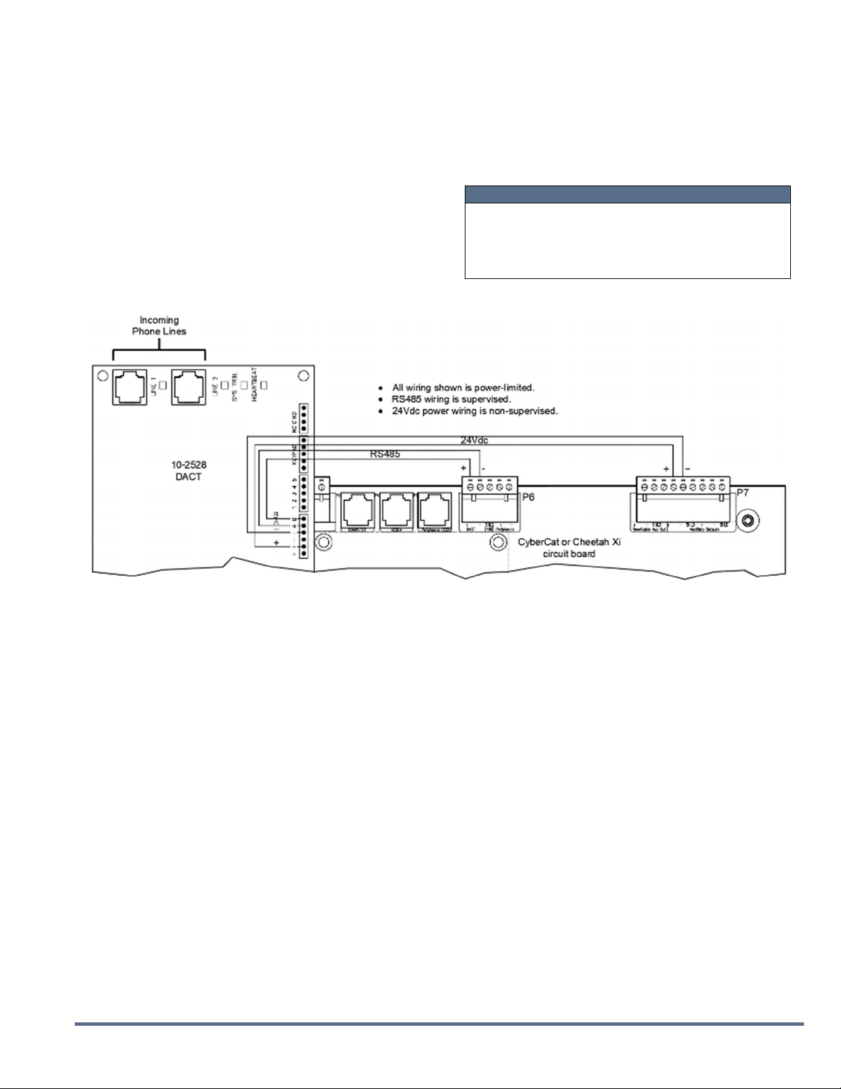
DACTWiring:CyberCat™50andCheetah™Xi50
Thewiringdiagrambelowshowshowtoelectrically
connecttheDACTintotheCyberCat™50andCheetah™Xi
50:
1. Installwiringtoconnect24VDCcontinuouspowerfrom
thesystemcontroller(terminalP6,Aux#1,+/‐)tothe
DACTasshownbelow.
2. Apply24VDCpowertotheDACTandprogramusingthe
10‐2477five‐zonehand‐heldDACTprogrammer.
3. InstallRS485wiringfromthesystemcontroller
(terminalP6)totheDACT(‐ toA;+toB),asshown
below.
4. Connectincomingphonelinesandtestforproper
operation.
NOTE
WhentheDACTmoduleisinstalled,theincomingphone
lines(power‐limited)mustberoutedseparatelyfrom
anynon‐power‐limitedrelayconnectionstothesystem
controller.
DACTWiring:CyberCat™50andCheetah™Xi50
Doc.No.06‐479● Rev.3,March2019ISO9001:2015CertifiedPage5of5
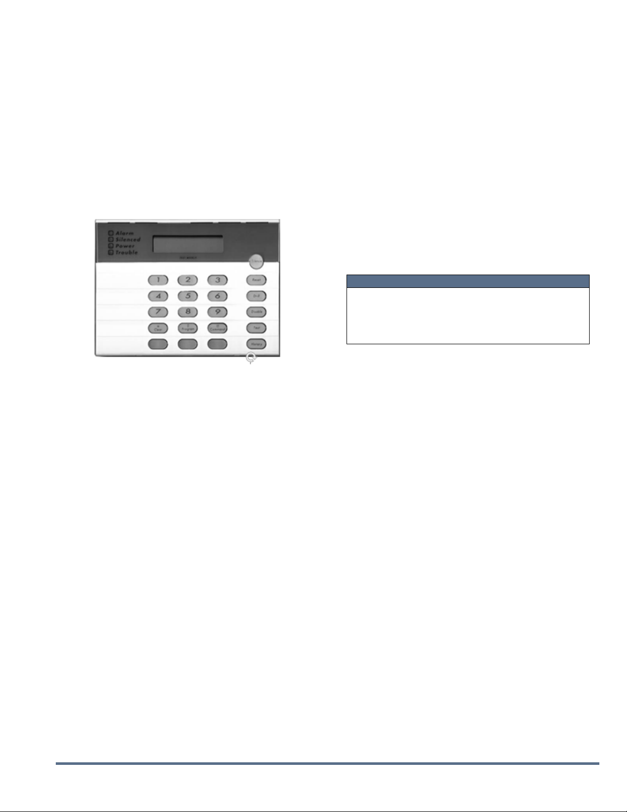
DACTProgramming
WhenusingtheintelligentRS485connection,theDACT
mustbeaddedtothecontrolpanel’speripheraldevicelist
(address2–32)andselectedforsupervision.Thisallows
troublewiththeDACTtobereportedtotheFikecontrol
systemandtransmittedtothereceivingstationononeof
thephonelines.
DACToperationalfunctionsmustbeprogrammedintothe
deviceusingthe10‐2477(BoschFMR‐DACT‐KEYPAD)five‐
zone,hand‐heldprogrammer,asshownbelow.
RefertoBoschdocumentFPT‐DACTOperationand
InstallationGuidefordialer‐specificoptionsand
programminginstructions.Thefollowingoptionsmustbe
configuredintotheDACTforproperoperationwithFike
controlsystems:
SystemDateandTime
AccountNumbers
PhoneNumbers
PhoneControl(reportingformat)
ReportSteering(phonetwoasbackuptype)
Supervision
BusAddress=133(donotchange)
SuperviseBus=Yes(donotchange)
NOTE
IfusingtheDACT’soptionalprogrammablepointinputs
forcommunicationtothereceivingstation,referto
BoshdocumentFPT‐DACTOperationandInstallation
Guideforwritingandprogramminginstructions.
DACTProgrammer
Table of contents
Other Fike Cell Phone manuals


