Fleming Music Australia SST 15 User manual
DIY GUITAR KIT
DIY GUITAR KITDIY GUITAR KIT
DIY GUITAR KIT
S
SS
SS
SS
ST 1
T 1T 1
T 15
55
5
Joint: Bolt-on
Body: Ash
Neck: Maple
Fingerboard: Rosewood
Tuning Machines: Chro e Die-cast
Scale Length: 25.5"
Fret: 22
Control: 1V, 2T, 5-Way Selector
Pickups: S-S-S
Hardware: Chro e
Bridge: Tre olo
Pickguard: 3-Ply White Pickguard

1
SST 15 FLEMING DIY GUITAR KIT Assembly Instructions
Please read these instructions carefully before beginning in order to have a
complete overview of the project. There are six steps that you will follow to
complete your Electric Guitar Kit.
1. Check and Identify Parts
2. Finishing the Body and Neck
3. Shaping the Headstock
4. Assembling the Body
5. Assembling the Neck
6. Setup
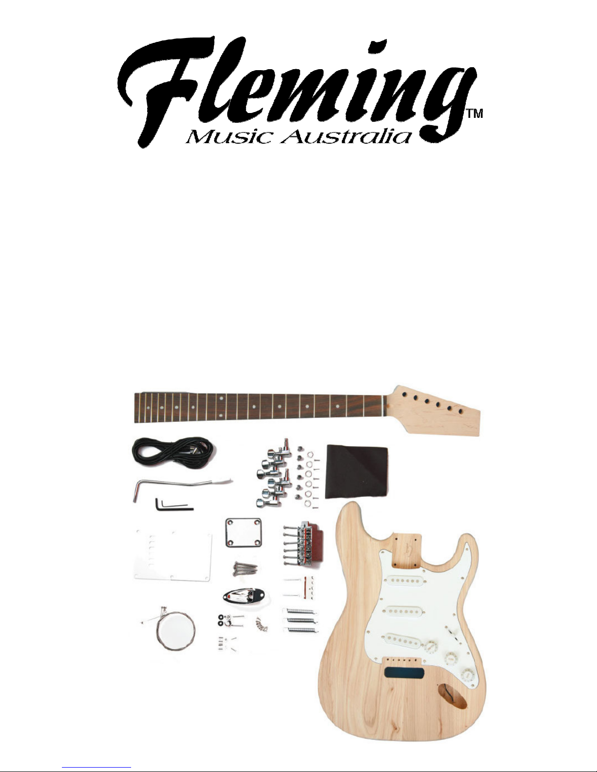
CHECK AND IDENTIFY PARTS
Following is the list of parts that are included with your kit. In the unlikely
event that parts are missing from your kit you may order replacements from
your local music shop or directly from us.
Quantity Description
A 1 Ash Body
B 1 Maple Neck, Rosewood Fingerboard
C 1 Chrome Output Jack
D 1 3 Ply Pickguard Assembly
E 1 Chrome Tremolo Unit
F 1 Chrome Tremolo Arm with white tip
G 1 Spring Claw
H Set of 3 Springs
I 1 White Back Plate
J Set of 6 Chrome Tuning Machines
K Set of 2 Strings Tees
L 1 Chrome Neck Plate and neck plate pad
M Set of 6 Strings (.09 - .42)
N 1 2m Guitar Lead
O 2 Chrome Strap Buttons, Screws and Rubber Pads
FINISHING THE BODY AND NECK
Although the overall tone and playing characteristics of the instrument will not
be affected, a high quality finish is a real source of pride to the builder.
Both the neck and body of your FLEMING DIY Electric Guitar Kit have been
sanded and are ready for your final sanding and finishing.

2
FINISHING THE BODY
First you will need to decide whether you would like a natural finish or a
coloured finish on the body. For a natural finish go directly to Clear Coat.
COLOR COAT
For the colour coat your first stop is a shop that specializes in automotive
products or any shop that sells acrylic paints (e.g. your local hardware store).
The acrylic lacquer made by the automotive industry is particularly well suited
to your needs. In addition to providing a full range of colour choices, acrylic
lacquer is extremely durable and resistant to cracking.
Choose your colour from the many available shades (including metallic
options) used for automobile touch up work. A spray can will make your job
much easier and produce fine results.
Hang the body as shown in Figure 1. Begin each spray stroke in the air on
one side of the body and continue until you reach the air on the other side.
Overlap each stroke by one half, and every other stroke spray crosswise, then
length wise. This technique will provide an even colour distribution.
Although lacquer dries quickly, and successive coats may be sprayed in a
short period of time, attempts to spray too much in one coat can result in runs
or bubbles in the finish. Spraying should not be attempted on excessively
humid or rainy days.
One or two coats of colour should be enough. It should not be necessary to
sand between coats unless there are drips, runs or bug feet (!) to be levelled.
All exposed surfaces should be dead level and have a nice satin gloss.
CLEAR COAT
The clear lacquer topcoat is also available at most auto parts store. If you
have applied a colour coat, it is advisable to select the same brand of clear
lacquer to assure compatibility.
The clear coat is applied to the body using the same technique as described
for the colour coat. Two or three coats of clear should be adequate.
For best results the body finish should be allowed to harden for one week
before the final rub out and polish.
Note: To avoid runs and drips, hold can 6-10 inches from surface. For
best results follow directions on spray can.
CAUTION: Remember that spray paint is extremely flammable. Do not spray
near open flames, heat or sparks. The area where you spray must be well
ventilated while spraying and until all vapour is gone. Do not smoke! Do not
breathe the vapour and keep doors and windows open during application and
drying.

3
SHAPING THE HEADSTOCK
The peg head of the SST 15 has been left slightly oversized and this is your
chance to express your individuality and to make a guitar that is truly your
own. First, decide on the shape of the headstock that you would like to use
and draw the outline on the top surface of the peg head. Use this drawing as
a template to design several headstock shapes and then choose the one that
is “YOU”
- Using a bandsaw or simple coping saw, cut out the shape of your headstock
A half round file should be used to level the contoured edge of the peg head.
Finally, the edge should be sanded smooth with fine 400 grit sandpaper.
- Now you can “Sign” your head stock and draw your own designed “logo”
onto the head stock. Practice on some plain paper first. Tracing paper is very
helpful for this process. Note: Some headstock shapes are protected by
trademark restrictions and we do not recommend that you use them.
NECK (PART B)
Before application of the finish to the back of your neck, the fingerboard
should be masked off to prevent finish from adhering to the fretted surface
(see Figure 3). A screw can be inserted temporarily in one of the four holes at
the heel which will later be used for attaching the neck to the body. Secure a
wire or cord to that screw so that the neck can be hung during spraying.
The neck is traditionally finished clear and the clear lacquer that you used for
the body is recommended. Spray all exposed surfaces including the face of
the headstock evenly. The neck of your guitar has been not been sealed so it
may be necessary to sand between coats. You will need to sand if runs,
orange peel or drips appear. Use the same procedure that you followed on
the body – again, two or three coats should do the job. Final rub out and
polishing takes place about one week later when the lacquer has cured.

4
FINAL RUBBING AND POLISHING
After allowing the clear, lacquered surfaces to dry and harden for at least one
week, sand lightly with non-loading 400 grit sandpaper. During sanding be
sure to place a firm material behind the sandpaper (a sanding block for
example) A large rubber eraser works fine. The eraser is flexible enough to
sand the gradual curves but is stiff enough to prevent the sharper edges (of
the headstock, for example) from being rounded off. Be sure to sand with the
grain of the wood.
All sanded surfaces should now be a bit dull, indicating that the finish is flat
and level. Now repeat the sanding process with very fine 600 grit sandpaper
using water and a small amount of dishwashing detergent as a lubricant. This
will remove any sanding marks left by the previous step and leave all surfaces
a dull gloss.
The finish may now be rubbed out using a medium grade automotive
rubbing compound (DuPont White Polishing Compound for example). The
compound should be used sparingly with fairly good pressure at first –– as a
high gloss develops, pressure should be diminished. An extra fine grade of
polishing compound may be used to get that final bit of gloss. If instructions
have been followed you should now have a professional quality finish. You
can protect your work with a light wax (Guitar Polish for example).
ASSEMBLING THE BODY
1. PICKGUARD ASSEMBLY (PART D)
The three wires from the pickguard assembly must be connected to the three
wires that you have already fed into the pickup cavity. Each wire has a mini
plug in its end. First slide back the shrink tubing and plug white to white, black
to black and blue to blue (See Figure 5).Carefully slide the shrink tubing over
the connectors and heat the tubing with a match to permanently seal the
connection. Attach the pickguard assembly to the body with the 11screws
provided.
Note: The pickguard has been covered with a clear plastic film to protect it
from scratches during transit and assembly. It should be removed after the
guitar has been assembled.
5
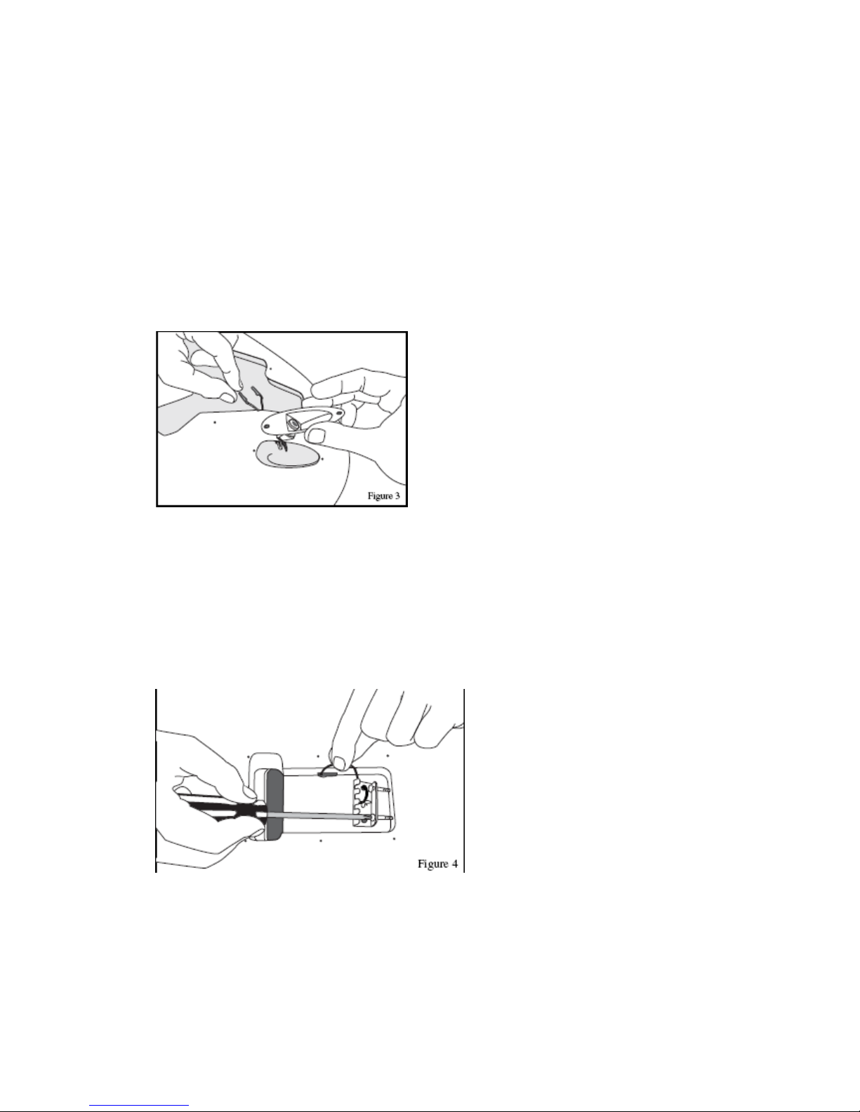
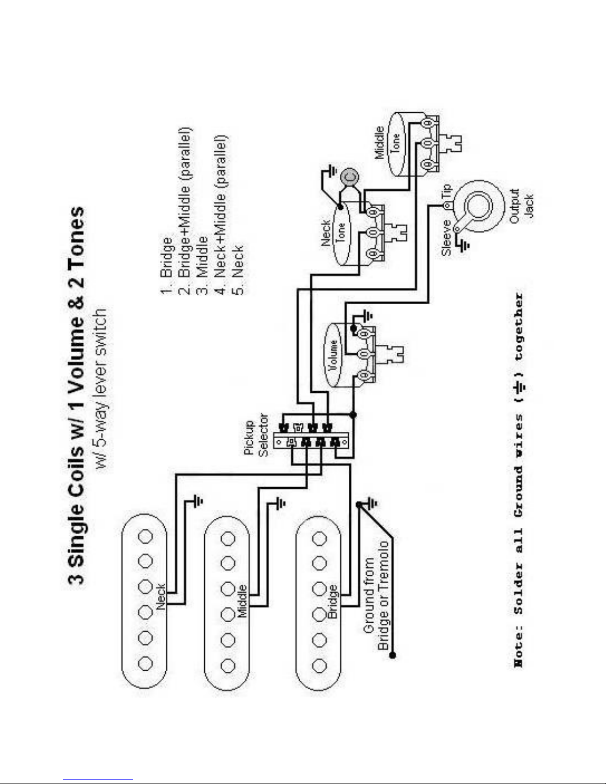
2. OUTPUT JACK (PART C)
The cavity for the output jack is located on the lower right hand side of the
body. The two wires or two ends of the dual core wire (depending on which
one you have) from the pickguard must be fed through the hole that is
between the pickguard cavity and the output jack cavity then they are to be
connected to the output jack. The “hot wire” which is the wire with a plastic
shield around it is to be soldered to the terminal that is for the TIP of the guitar
lead. The “ground wire” is to be soldered to the terminal that connects the
main shaft of the guitar lead. (see the provided wiring diagram).
After the soldering has been done, use the two screws that have been
provided to screw the output jack plate to the body of the guitar.
3. SPRING CLAW (PART G)
Turn the body over and attach the spring claw, connect by soldering the
spring claw to the ground wire which should be directed through hole in the
cavity so that it enters the pickup cavity.
Note: Most players prefer to leave the two screws quite loose in order to have
more relaxed spring tension-more about that later during set up. This can be
adjusted later.

6
4. TREMOLO UNIT (PART E)
(1) Attach the tremolo unit using the six screws provided. Do not over tighten.
(2) Attach springs between the spring claw and the tremolo block – most
players use 3 springs only.
(3) Screw the tremolo arm into the tremolo unit.
5. BACKPLATE (Part I)
Attach the backplate to cover the spring cavity. This step is optional. Many
players leave this plate off in order to easily access the tremolo block ––
especially for changing strings. It is up to you whether you want to put it on or
not.
6. STRAP BUTTONS (PART O)
There are two chrome strap buttons. One is screwed onto the butt of the
guitar and the other onto the left horn of the body. Insert the screw into the
Strap Button then through the hole of the black rubber Strap Button Pad and
screw to the body of the guitar.
7
ASSEMBLING THE NECK
TUNERS (PART J)
Push the six bushing into the washers then into the holes in the face of the
headstock then attach the 6 tuners using the 6 screws provided.
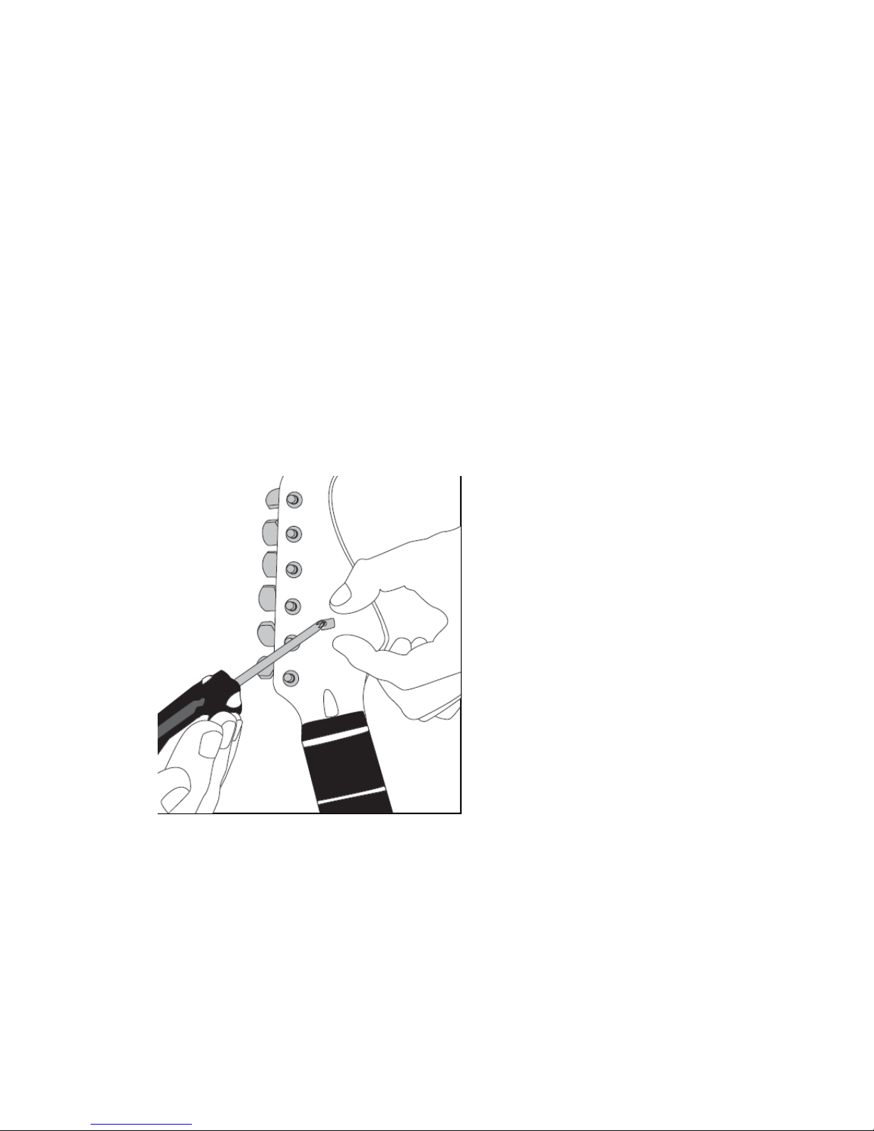
STRING TREE (PART K)
The string tree is now attached to the peg-head. (see figure 6) Locate the
small hole in the face of the peghead about 3 inches above the string nut. Slip
the string notches onto the screw followed by the round cylindrical spacer.
The string tree pulls the first and second strings of the guitar downward. That
down-ward pressure will keep the strings from popping out of the nut slots
while you are playing. We recommend doing this once the strings are on so
you can line up the string tees directly over the strings.
NECKBODY ATTACHMENT
We will now attach the neck to the body using the four large screws. The neck
plate acts as a large washer and covers the locator hole on the back of the
body.
SET UP
STRINGS (PART M)
Put on the strings and tune to pitch.
1. TREMOLO ADJUSTMENT
If the tremolo leans forward and rests against the body adjust the spring plate
using the two screws holding it to the body to increase or decrease tension on
the springs. This floating tremolo system should be parallel to the body at rest.
8
2. TRUSS ROD ADJUSTMENT
The adjustable truss rod in the neck of your Guitar has been shop adjusted
and should not require any change. If the neck should develop a dip or hollow
spot over time it can be removed by tightening the truss rod adjustment nut
that protrudes from the base of the headstock just above the nut.
A back bow or hog-back can be removed by loosening the nut. Great care
should be taken with truss rod adjustments where as little as 14 of a turn can
vastly alter the shape of a neck. A broken truss rod of course means a costly
replacement.
3. STRING ACTION
The string action refers to the height of the strings above the frets. If the
action is too low, the strings will buzz on the frets. If it is too high the guitar will
be difficult to play.
4. ACTION AT THE NUT
Setting the string action that is right for you starts at the string nut. The slots at
the string nut should already be close to perfection but you might want to
make some adjustment. Here’s how to do it!
Push the sixth string down between second and third fret. The space between
the top of the first fret and the bottom of the string should be about .006” or
just about the thickness of the paper that these instructions are written on. If
the gap is wider than .006” you should deepen the slot with a small needle file
until it is correct. DO NOT FILE TOO DEEP! If the slot is too deep you can fill
the slots with a mixture of white plastic sanding dust and super glue and then
re-shape the slot.
Repeat this same procedure for the other 5 strings. The action at the nut is
either right or wrong; it is not a matter of personal preference.
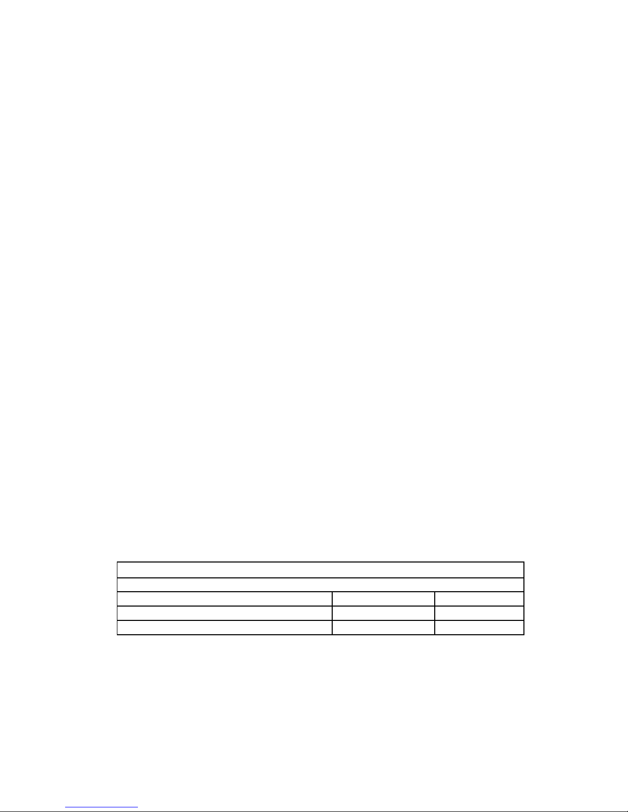
Now let’s adjust the height of the strings over the 12th fret. Minor adjustments
in the string action can be made by raising or lowering the individual saddles
on the tremolo bridge with the small hex key that has been provided with your
Guitar Kit. Following is a chart to assist you. This action adjustment is a
matter of personal preference. There should be a gradual increase in height
from the first to the sixth string.
STRING HEIGHT AT THE 12
TH
FRET
First String Sixth String
Low Action 1/32″1/16″
Medium Action 1/16″3/32″
High Action 3/32″1/8″
Action can also be adjusted by changing the angle of the neck. This can be
done by inserting small shims between the neck and the body to increase or
decrease the neck angle.
9
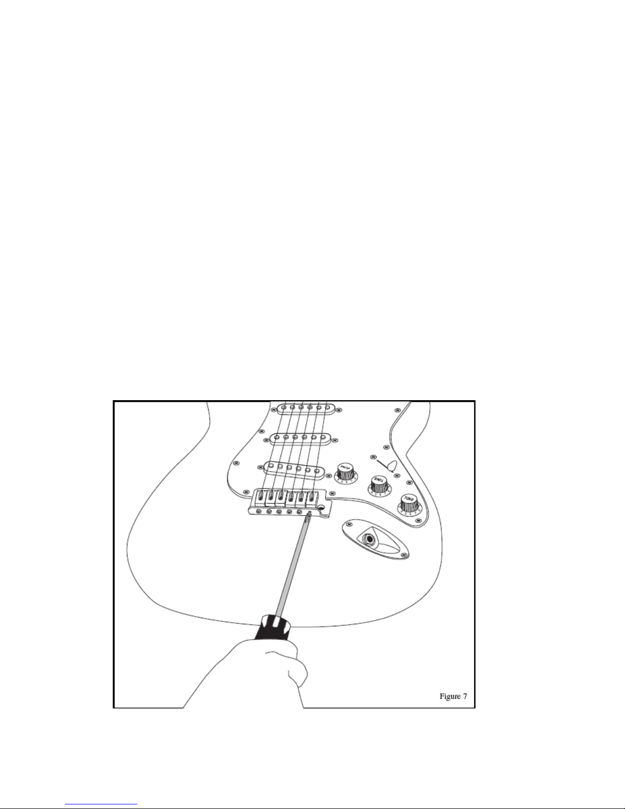
5. INTONATION
The saddles on the tremolo bridge can be adjusted to compensate for the
pitch modification that occurs when the string is stretched as it is fretted. This
adjustment is made by tightening or loosening the set screws at the rear of
the tremolo bridge. (See Figure 7)
Start by tuning your guitar and sounding a harmonic chime directly above the
twelfth fret on the sixth string. Now fret the sixth string at the twelfth fret and
compare that pitch to the harmonic. If the fretted note is higher than the
harmonic pitch, tighten the set screw to lengthen the string. If the fretted note
is lower than the harmonic, loosen the set screw to shorten the string length.
When the harmonic and the fretted note sound the same note, the saddle is at
the correct position. Repeat this procedure for the other five strings.
6. PICKUP HEIGHT
Each single coil pickup is adjustable on the bass and treble sides. Finding the
best combination of tone and volume will require some experimentation. A
good place to start is to adjust the pickup height so that the first string is about
18 over the pickup pole and the sixth string is about 316 over its pole.
Electric Guitar setup is an art in itself. For more detailed discussion we highly
recommend that you go onto the internet and search on “electric guitar
setups”.
Web sites to visit: www.flemingmusic.com.au & www.lacemusic.com.au
10
Table of contents
Popular Guitar manuals by other brands


Fender
Fender Deluxe Active Jazz Bass V Wiring diagram

Warwick
Warwick RockBass Streamer Standard Specifications

Squier
Squier Affinity Mini Strat Specifications

Grizzly
Grizzly H8181 owner's manual

Fender
Fender American Standard Telecaster supplementary guide

Fender
Fender Highway One Telecaster Wiring diagram


