FLEMING SPR01 User manual
DIY GUITAR KIT
DIY GUITAR KITDIY GUITAR KIT
DIY GUITAR KIT
SP
SPSP
SPR
RR
R
01
0101
01
Joint: Bolt-on
Body: Basswood with Flamed Maple Top
Neck: Maple
Fingerboard: Rosewood
Tuning Machines: Chrome ie-cast
Scale Length: 628mm/24.75"
Fret: 22
Control: 1V, 1T, 3-Way Toggle
Pickups: H-H
Hardware: Chrome
Bridge: Tune-O-Matic

1
SPR 01 FLEMING DIY GUITAR KIT Assembly Instructions
Please read these instructions carefully before beginning to build your guitar
in order to have a complete overview of the project. There are five steps that
you will need to follow to complete your Electric Guitar Kit.
1. Check and Identify Parts
2. Finishing the Body and Neck
3. Shaping the Headstock
4. Assembling the Guitar
5. Setup
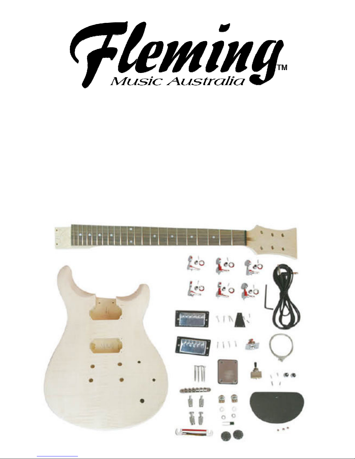
Following is the list of parts that are included with your kit. If parts are lost or
run through the stump shredder during assembly you may order replacements
from your local music shop or directly from us.
Quantity Description
A 1 Basswood with Flame Maple Carve top body
B 1 Maple Neck with Rosewood Fingerboard
C 1 Output Jack & Chrome Jack Plate
D 1 each 500 Ohm Tone Pot & 500 Ohm Volume Pot
E 1 3 Way Pickup Toggle Switch
F 1 Black Single Ply Black Plate with Screws
G 1 Neck Position Pickup with Black Mounting Ring
H 1 Bridge Position Pickup with Black Mounting Ring
I 1 Chrome Stop Tailpiece
J 1 Chrome Tune-o-Matic Bridge
K Set of 6 Chrome Machine Heads
L 1 Chrome Neck Plate with Neck Plate Pad
M Set of 6 Electric Guitar Strings
N 1 2m Guitar Lead
O 2 Chrome Strap Buttons, Screws and Rubber Pads
P 1 Truss Rod Cover and Screws
Q 2 Control Knobs

2
FINISHING THE BODY AND NECK
Although the overall tone and playing characteristics of the instrument will not
be affected, a high quality finish is a real source of pride to the builder.
Both the neck and body of your Electric Guitar Kit have been sanded and are
ready for final sanding and then finishing.
FINISHING THE BODY
First you will need to decide whether you would like a natural finish or a
coloured finish on the body. For a natural finish, go directly to "Clear Coat".
COLOR COAT
For the colour coat your first stop is a shop that specializes in automotive
products. The acrylic lacquer made by the automotive industry is particularly
well suited to your needs. In addition to providing a full range of colour
choices, acrylic lacquer is extremely durable and resistant to cracking.
Choose your colour from the many available shades (including metallic
options) used for automobile touch up work. A spray can will make your job
much easier and will produce great results.
- Hang the body as shown in Figure 1. Begin each spray stroke in the air on
one side of the body and continue until you reach the air on the other side.
Overlap each stroke by one half, and every other stroke spray crosswise, then
length wise. This technique will provide an even colour distribution.
Although lacquer dries quickly, and successive coats may be sprayed in a
short period of time, attempts to spray too much in one coat can result in runs
or bubbles in the finish. Spraying should not be attempted on excessively
humid or rainy days.
- One or two coats of colour should be enough. It should not be necessary to
sand between coats unless there are drips, runs or bug feet (!) to be levelled.
All exposed surfaces should be dead level and have a nice satin gloss.
This picture is used for
Illustration purposes only
(It is not the PRS model)
3
CLEAR COAT
The clear lacquer topcoat is also available at most auto parts stores. If you
have applied a colour coat, it is advisable to select the same brand of clear
lacquer to assure compatibility.
- The clear coat is applied to the body using the same technique as described
for the colour coat. Two or three coats of clear should be adequate.
For best results the body finish should be allowed to harden for one week
before the final cut and polish.
Caution: Remember that spray paint is extremely flammable. Do not spray
near open flames, heat or sparks. The area where you spray must be well
ventilated while spraying and until all vapour is gone. Do not smoke! Do not
breathe the vapour and keep doors and windows open during application and
drying.
SHAPING THE HEADSTOCK
The headstock of the SLPP 380B has been left extra long and here is a
chance to express your individuality and to make a guitar that is truly your
own. First, decide on the shape of the headstock that you would like to use
and draw the outline on the top of the headstock.
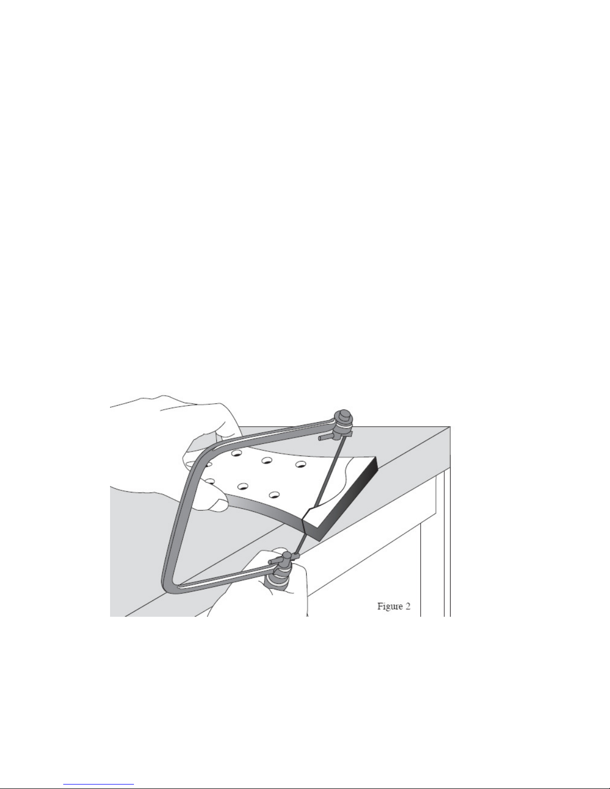
Using a bandsaw or simple coping saw, cut out the shape of your headstock
(see Figure 2). A half round file should be used to level the top edge of the
headstock. Finally, the edge should be sanded smooth with fine 400 grit
sandpaper.
Note: Some headstock shapes are protected by trademark restrictions and we
do not recommend that you use them.

4
NECK
Before application of finish, the fingerboard should be masked off to prevent
finish from adhering to the fretted surface (see Figure 3). A screw can be
inserted temporarily in one of the four holes at the heel which will later be
used for attaching the neck to the body. Secure a wire or cord to that screw so
that the neck can be hung during spraying.
- Spray all exposed surfaces evenly. The neck of your Guitar has been
sanded level so it should not be necessary to sand between coats unless
runs, orange peel or drips appear. Use the same procedure that you followed
on the body – again, two or three coats should do the job. The face of the
headstock is traditionally finished black. The final cut and polish takes place
about one week later when the lacquer has cured.
FINAL RUBBING AND POLISHING
After allowing the clear lacquered surfaces to dry and harden for at least one
week, sand lightly with non-loading 400 grit sandpaper (commonly known as
“wet and dry”). During sanding be sure to place a firm material behind the
sandpaper. A large rubber eraser works fine. The eraser is flexible enough to
sand the gradual curves but is stiff enough to prevent the sharper edges (of
the headstock, for example) from being rounded off. Be sure to sand with the
grain of the wood.
- All sanded surfaces should now be a bit dull, indicating that the finish is flat
and level. Now repeat the sanding process with very fine 600 grit sandpaper
using water and a small amount of dishwashing detergent as a lubricant. This
will remove any sanding marks left by the previous step and leave all surfaces
a dull gloss.
- The finish may now be rubbed out using a medium grade automotive
rubbing compound (DuPont White Polishing Compound for example). The
compound should be used sparingly with fairly good pressure at first –– as a
high gloss develops, pressure should be diminished. An extra fine grade of
polishing compound may be used to get that final bit of gloss. If instructions
have been followed you should now have a professional quality finish. You
can protect your work with a light wax –– Guitar Polish is a good choice.
5
ASSEMBLING THE GUITAR
1. NECK/BODY ATTACHMENT
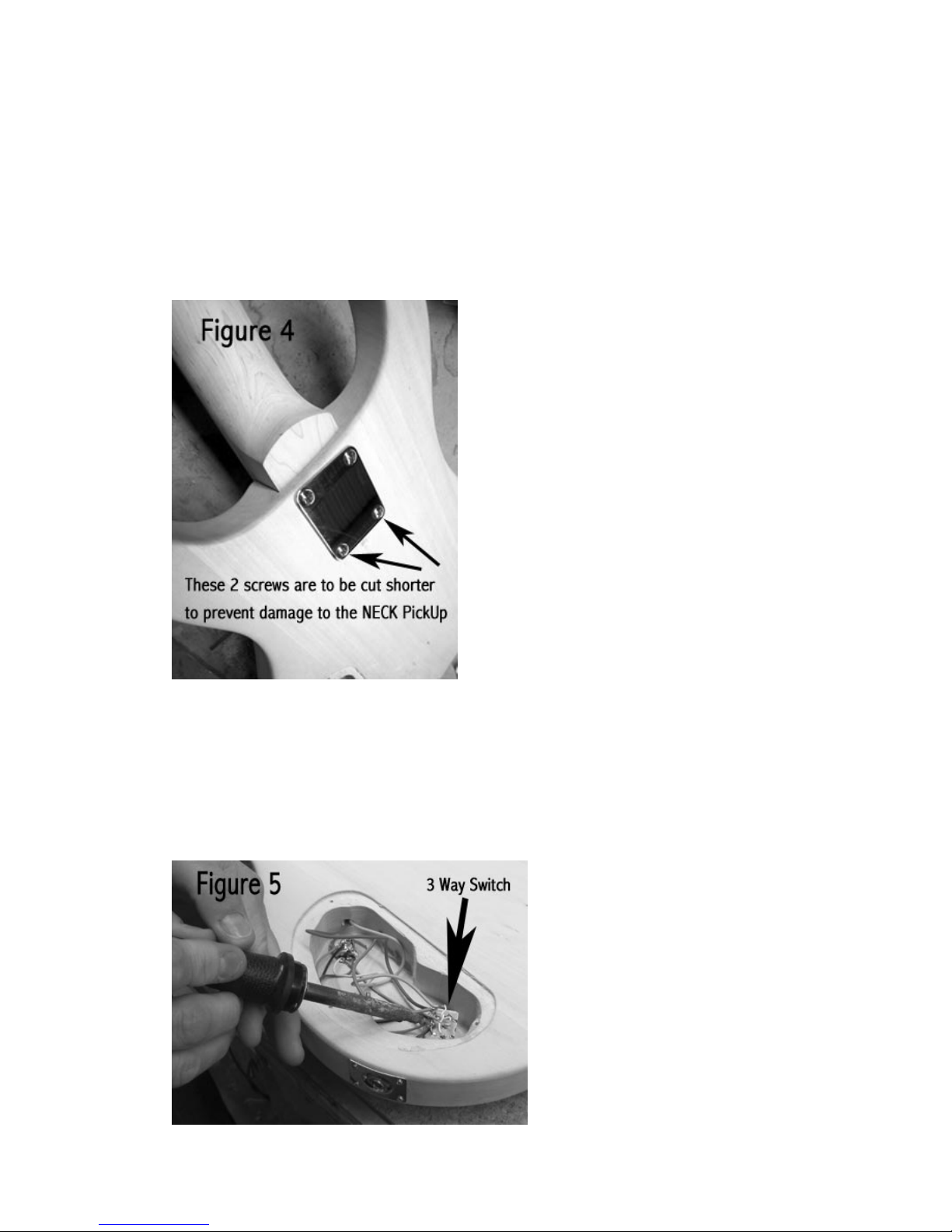
Attach the neck to the body using the four large screws provided.
NOTE: The 2 neck screws WILL have to be cut shorter!!! The 2 screws
closest to the middle of the guitar. (See figure 4)
The neck plate (Part L) acts as a large washer and covers the locator holes
on the back of the body.
2. THREE WAY PICKUP SWITCH (PART E)
Looking at the back of the guitar body, push the threaded shaft of the switch
through the 1/2” hole on the bottom right of the guitar. While still holding the
switch in place turn the body over and slip the washer onto the protruding
shaft and loosely screw on the nut. Look at the switch mechanism inside the
cavity. There are 3 terminals on the back of the switch that you will be
soldering to. (See figure 5)

6
3. NECK POSITION PICKUP (PART G)
The cavity for the neck position humbucking pickup is located on the upper
part of the body closest to the neck pocket. As you look into the cavity you will
notice that a hole has been drilled that connects the cavity for the neck
position pickup to the cavity that will house the bridge position pickup. Notice
also that the Neck Position Pickup has a thinner mounting ring than the Bridge
Position Pickup. Run the wire attached to the neck position pickup into the
hole from the neck cavity to the bridge pickup cavity. This is same hole that
the wires coming from the selector switch have been run through. Use the
four 5/8” screws to attach the neck position pickup to the body.
4. BRIDGE POSITION PICKUP (PART H)
There is a hole connecting the bridge position cavity to the control cavity. The
black wire from the neck position pickup should run through that hole into the
control cavity. The red wire that is attached to the bridge position pickup is
now pushed through that same hole emerging into the control cavity also.
Attach the bridge position humbucking pickup to the body with four 5/8”
screws.
5. VOLUME AND TONE CONTROLS (PART D)
There is one volume and one tone control for this guitar. The 1 volume and 1
tone potentiometers are assigned to both pickups. As you play the guitar, the
volume and tone pots sit next to each other. The volume is on the left side
and the tone control is on the right side. Install the volume and tone controls in
the 3/8” holes by inserting the control pots through the holes, placing the
provided washer and then nut. Hold the control pot to stop it from spinning
when you tighten the nut. DO NOT OVERTIGHTEN!
6. CONNECTING CIRCUITS
The cavity for the controls on the back of the body should now resemble a
spaghetti factory. Use the wiring diagram on page 10 to wire your guitar up.
You will need to use a soldering iron and some solder. (The solder has been
provided with your kit) Soldering is not a hard thing to learn as you will find
there are many FREE LESSONS online on how to solder. Soldering irons are
very inexpensive.
PLEASE REMEMBER though that they do get VERY HOT and MUST be
kept away from children. Please turn your soldering iron OFF and unplug it
from the wall when it is not in use.
REMEMBER - SAFETY FIRST!

7
7. THE TAILPIECE (PART J)
Take a look at the bridge and tailpiece hardware and distinguish the
difference between the bridge studs and the tailpiece studs. The tailpiece
studs have a much larger set screw.
Install the tailpiece first. Separate the tailpiece mounting parts from the
threaded bushings. These bushings must be driven in place in the two holes
closest to the rear of the guitar body. It will be necessary to ground the
electronic circuitry to the tailpiece. The control cavity is at the back of the
guitar body. On the inside wall of this cavity you will see a small 1/8” hole.
Run the stripped end of the ground wire through this hole until it emerges in
the hole drilled for the tailpiece bushing. Form the naked wire into a loop,
wrap it around the bushing and tap the bushing tightly into the hole. This will
ground the circuit.
- Installing the tailpiece bushings may be done with a plastic headed mallet or
place a small piece of wood on top of the bushing to prevent damage and tap
the bushing in place with an ordinary hammer. Now screw the tailpiece
mounting screws back into the bushings.
8. THE BRIDGE (PART J)
Now tap the bridge bushings into place and screw in the bridge mounting
studs. Attach the bridge.
9. OUTPUT JACK (PART C)
The output jack (once wired) will be attached to the neck pickup tone control
pot by a blue grounding wire. Find the wire running from the pickup selector
switch and solder it to the wire on the output jack. Push the output jack and its
wire through the 7/8” hole that has been drilled between the control cavity and
the edge of the body.
Attach the output jack plate (Part C) to the output jack using the washer and
nut provided. Screw the output jack plate to the body with the two 3/8” screws
provided.
10. BACK PLATE (PART F)
Carefully stuff all of the wiring into the control cavity and attach the back plate
using the screws provided.
11. TUNERS (PART K)
Attach the six tuning machines to the headstock of the guitar putting a washer
beneath each threaded bushing. A small set screw is put in place to prevent
the tuner from rotating.
8
SET UP
Put on the strings and tune to pitch.
1. TRUSS ROD ADJUSTMENT
The adjustable truss rod in the neck of your Guitar has been shop adjusted
and should not require any change. If the neck should develop a dip or hollow
spot over time it can be removed by tightening the truss rod adjustment nut
that protrudes from the base of the headstock just above the nut.
A "back bow" or "hog-back" can be removed by loosening the nut. Great care
should be taken with truss rod adjustments where as little as 1/4 of a turn can
vastly alter the shape of a neck. A broken truss rod of course means a costly
replacement.
2. STRING ACTION
The string "action" refers to the height of the strings above the frets. If the
action is too low, the strings will buzz on the frets. If it is too high the guitar will
be difficult to play.
3. ACTION AT THE NUT
Setting the string action that is right for you starts at the string nut. The slots at
the string nut should already be close to perfection but you might want to
make some adjustment. Here’s how to do it!
Push the sixth string down between second and third fret. The space between
the top of the first fret and the bottom of the string should be about .006” or
just about the thickness of the paper that these instructions are printed on. If
the gap is wider than .006” you should deepen the slot with a small needle file
until it is correct. DO NOT FILE TOO DEEP! If the slot is too deep you can fill
the slots with a mixture of white plastic sanding dust and crazy glue and then
re-shape the slot. Repeat this same procedure for the other five strings. The
action at the nut is either right or wrong; it is not a matter of personal
preference.
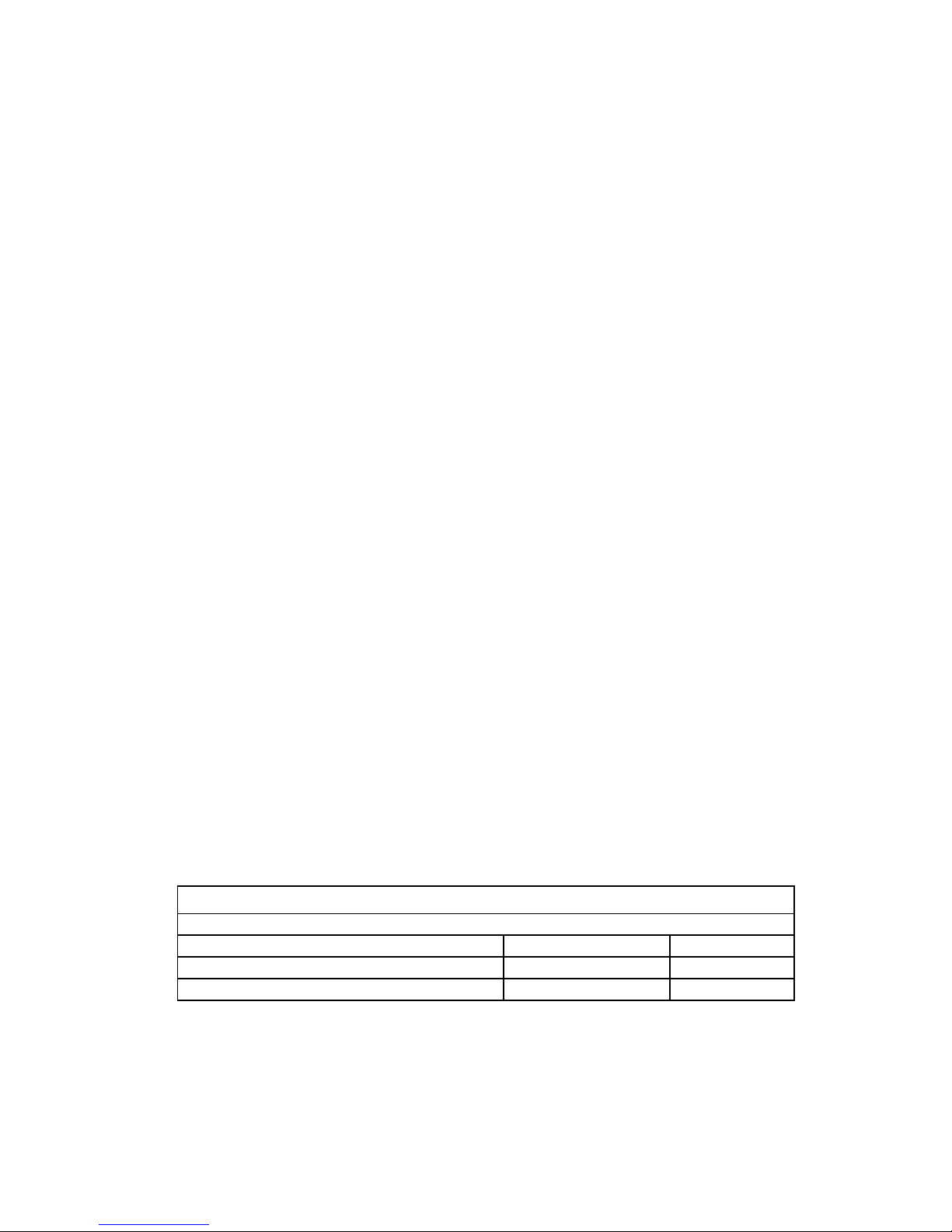
Now let’s adjust the height of the strings over the 12th fret. Adjustments to the
string action are made by raising or lowering the Tune-o-Matic Bridge with the
thumbwheel height adjusters. Following is a chart to assist you. This action
adjustment is a matter of personal preference. There should be a gradual
increase in height from the first to the sixth string.
String Height at the 12
th
fret
First String Sixth String
Low Action 1/32″1/16″
Medium Action 1/16″3/32″
High Action 3/32″1/8″
9
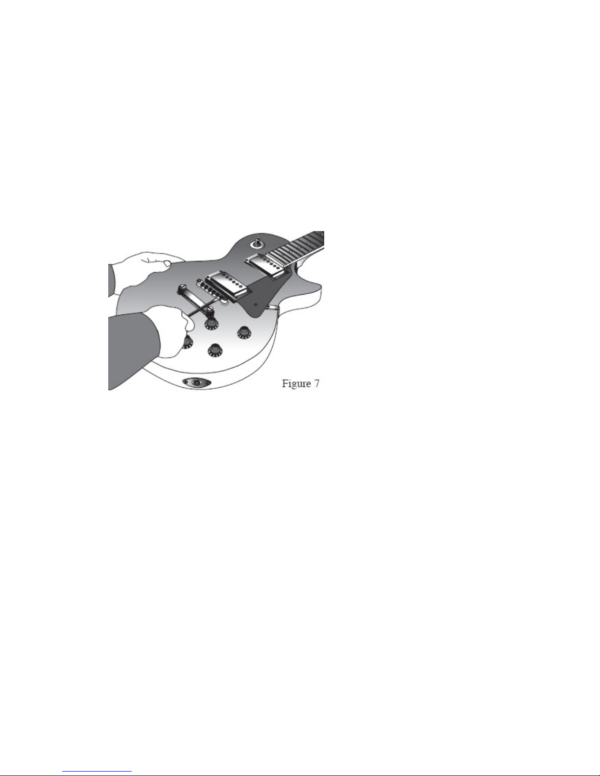
4. INTONATION
The saddles on the bridge can be adjusted to compensate for the pitch
modification that occurs when the string is stretched as it is fretted. This
adjustment is made by tightening or loosening the set screws at the rear of
the bridge (see Figure 7). Start by tuning your guitar and sounding a harmonic
chime directly above the twelfth fret on the sixth string. Now fret the sixth
string at the twelfth fret and compare that pitch to the harmonic. If the fretted
note is higher than the harmonic pitch tighten the set screw to lengthen the
string. If the fretted note is lower than the harmonic, loosen the set screw to
shorten the string length. When the harmonic and the fretted note sound the
same note, the saddle is at the correct position. Repeat this procedure for the
other five strings.
5. PICKUP HEIGHT
Each humbucking pickup is adjustable on the bass and treble sides. Finding
the best combination of tone and volume will require some experimentation. A
good place to start is to adjust the pickup height so that the first string is about
1/8" over the pickup pole and the sixth string is about 3/16" over its pole.
Electric Guitar setup is an art in itself. For more detailed discussion we highly
recommend searching "Electric Guitar Setups” on the internet. There you will
find a many experience people sharing their knowledge and techniques on
doing this.
SPECIAL NOTE: You of course have the option to upgrade any hardware
you want at any time should you feel it necessary. PickUps are one of
the most common upgraded items on a guitar. If you wish to upgrade
the pickups on this OR ANY guitar, Fleming Music Australia HIGHLY
RECOMMENDS upgrading to LACE PICKUPS. See our website for more
details.
Web sites to visit: www.flemingmusic.com.au & www.lacemusic.com.au
This picture is used for
Illustration purposes only
(It is not the PRS model)

10
Table of contents


