Flexzilla
Electric
Oper
ated,
Pist
on
Compr
essors
Safety
This manual contains very important informa on to
know and understand. This is provided for SAFETY
and to PREVENT EQUIPMENT PROBLEMS. To help un-
derstand this informa on, observe the following:
Danger indicates an imminently
hazardous situa n which, if not
avoided, will result in death or serious injury.
Warning indicates a poten ally
hazardous situa n which, if not
avoided, could result in death or serious injury.
Cau on indicates a poten ally
hazardous situa n which, if not
avoided, may result in minor or moderate injury.
No ce indicates important infor-
ma on, that if not followed, may
cause damage to equipment.
BasicGuidelines
CALIFORNIA PROPOSITION 65
This product or its power cord may
contain chemicals known to the
State of California to cause cancer and birth defects or
other reproduc ve harm. Wash hands a er handling.
1.
Allow only trained, authorized persons who
have read and understood these opera ng
instruc ons to use this compressor. Failure
to follow the instruc ons, procedures and
safety precau ons in this manual can result
in accidents and injuries.
2.
NEVER start or operate the compressor under
unsafe condi ons. Tag the compressor,
disconnect and lock out all power to it to
prevent accidental start-up un the condi-
on is corrected.
3.
Install, use and operate the compressor only
in full compliance with all per nent OSHA
regula ons and all applicable Federal, State
& Local Codes, standards and regula ons.
4.
NEVER modify the compressor and/or controls
in any way.
5.
Keep a first aid kit in a convenient place.
Seek medical assistance promptly in case
of injury. Avoid infec n by caring for any
small cuts and burns promptly.
Breathable Air
1.
NEVER use air from this compressor for
breathable air except in full compliance with
OSHA Standards 29 CFR 1910 and any other
Federal, State or Local codes or regula ons.
Death or serious injury can result
from inhaling compressed air
without using proper safety
equipment. See OSHA standards
on safety equipment.
2.
DO NOT use air line an -icer systems in air
lines supplying respirators or other equip-
ment used to produce breathable air. DO NOT
discharge air from these systems in unven -
lated or other confined areas.
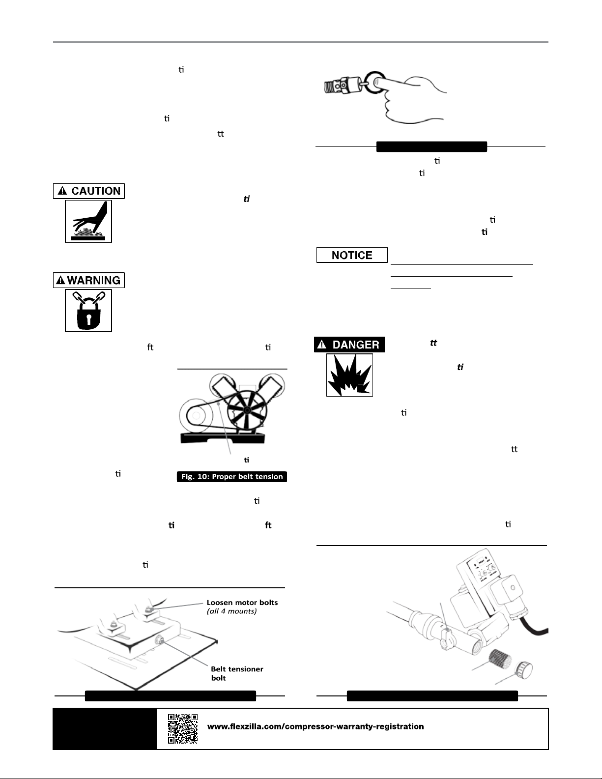
Pressurized Components
This equipment is supplied with a ASME designed
pressure vessel protected by an ASME rated relief
valve. Pull the ring before each use to make sure
the valve is func onal. Refer to figure 10. DO
NOT a empt to open valve while the machine is
under pressure.
Personal Protec ve Equipment
Be sure all operators and others around the
compressor and its controls comply with all appli-
cable OSHA, Federal, State and Local regula ons,
codes and standards rela ng to personal protec-
ve equipment. This includes respiratory protec-
ve equipment, protec on for the extremi es,
protec ve clothing, protec ve shields and barri-
ers, electrical protec ve equipment and personal
hearing protec ve equipment.
Inspec on
Inspect compressor prior to any
use. Check for external damage
that might have occurred during
transit. Be careful of moving parts
then test pulley by turning it
freely by hand.
Report any dam-
age to delivery carrier immediately.
Make sure pallet-mounted
compressors are firmly secured to
the pallet before moving. NEVER a mpt to move
a compressor that is not secure as serious injury or
property damage could occur.
A forkli may be necessary for unloading the
Flexzilla compressor. Use all forkli safety measures
and require a cer ed forkli operator. Refer to figure
1
for safe unloading procedure.
TO ACTIVATE
WARRANTY
Scan or go to
for warranty registration
Warranty only valid by following conditions expressed in the Warranty Statement section of the Compressor Operating Manual.