Fluke Calibration 7250i Quick start guide

PN
December 2010
©2010 Fluke Corporation. All rights reserved. Printed in USA.
All product names are trademark of their respective companies.
INS-H0001
LCD Display Upgrade
Upgrade Instructions
General
These instructions cover the replacement of the display assembly in the following instrument models: 7050; 7050i;
7250; 7250i; 7250xi; 7250LP; 7252; 7252i; and 7750.
These instruments are of modular construction, consisting of one or two primary sensors (depending on model type),
a pneumatic control system, an electronic control system, and a power supply.
Figure 1 shows the general layout of the various components within the instrument chassis as viewed from the top
(Model 7750i shown).
Access to the components is gained by removing the top cover.
Power
Supply
Primary
Sensors
Pneumatic
Control Module
Electronic
Control Module
gnk01.eps

INS-H0001
LCD Display Upgrade
2
Figure 1. Internal Arrangement (7750i)
Kit Contents
The Display Upgrade Kit (part number 7250-116-A) consists of the display assembly, a power cable and these
instructions.
WCaution
The original instrument configuration drives the display with 12 VDC, but the
new display operates on 5 VDC. Therefore, the original power cable
(red/black twisted pair) MUST be removed and replaced with the new cable
(blue/black twisted pair) to avoid damage to the new display (refer to
User Interface Panel Removal; and Replacement Display Assembly sections.
Safety
These products have been designed to be completely safe when installed and operated in accordance with their
ratings and procedures published in the user’s manual supplied with the instrument.
The equipment operates from voltages that can be lethal, and pressure supplies that can cause injury.
Maintenance and repair must only be undertaken by suitably qualified technicians and good engineering practice for
all procedures in this publication. (A qualified technician must have necessary technical knowledge, documentation,
special test equipment and tools to carry out the required work on this equipment.
Pressure Safety
Safely release the pressures in the instrument before disconnecting any pipes from the pressure/vacuum sources or
the Device Under Test (DUT). Disconnect all pneumatic services and other connections to the rear panel before
removing the instrument cover.
On no account permit pressures greater than those indicated on the rear panel as the supply pressures to be connected
to the instrument.
Electrical Safety
Hazards exist when the instrument cover is removed — power down the instrument and disconnect the power cord
before removing cover.
The instrument is designed to be completely safe when used with the Options, Accessories and replacement parts
supplied by the manufacturer. Attention is drawn to the installation of the electrical supply.

INS-H0001
LCD Display Upgrade
3
Procedure
Top cover Removal
1. Remove the 4 screws securing the top panel to the enclosure.
2. Push the top cover towards the rear of the instrument, and lift clear.
gnk02.bmp
Figure 2. Top Cover Removal

INS-H0001
LCD Display Upgrade
4
Primary Sensor Removal
General
With instruments that have two primary sensors, it is important to ensure that they are refitted in their original
positions to avoid damage to the sensors. Therefore, it is good practice to make careful note of their respective
positions and pneumatic and electrical connections BEFORE removal from the instrument chassis. Each sensor has a
serial number tag on the face where connections are made, but additional labels/marking may be useful. Carefully
label/mark the pneumatic tubing and electrical cables to avoid confusion during reassembly. Digital photographs can
also be helpful.
1. Disconnect the tubing and electrical connections from the primary sensor to be removed.
2. Carefully tilt the instrument until it is resting on one side.
3. Support the sensor assembly, and remove the four mounting screws and lock washers from the chassis
(Figure 3).
4. Carefully lift the sensor assembly away from the instrument chassis.
gnk03.bmp
Figure 3. Primary Sensor Removal
INS-H0001
LCD Display Upgrade
5
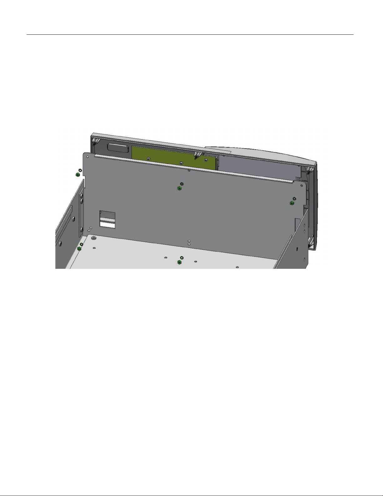
User Interface Panel Removal
1. Turn the chassis back to rest on its rubber feet.
2. Remove the six nuts and lock washers that hold the interface panel.
3. Tilt the panel and disconnect electrical cables from the keyboard and the display.
4. Disconnect display backlight power cable (red/black twisted pair) from motherboard assembly inside the
chassis. This cable must be discarded with the old display assembly — see warning note in the General
section.
gnk04.bmp
Figure 4. Interface Panel Removal

INS-H0001
LCD Display Upgrade
6
Replacing Display Assembly
1. Unscrew four screws ad lock washers, remove P-clip and lift out display assembly.
2. Locate new display assembly in cutout in user interface panel, with PCA assemblies toward the lower
edge.
3. Refit four screws and lock washer, with P-clip fitted to lower right-hand side mounting point
— DO NOT OVERTIGHTEN.
4. Connect new display backlight cable (blue/black twisted pair) and loop once through P-clip for strain
relief.
gnk05.bmp
Figure 5. Display Removal

INS-H0001
LCD Display Upgrade
7
Re-assembly
1. Feed new display backlight cable (blue/black twisted pair) through slot in front panel of chassis, and
connect to the mating connector (marked DISP) on the motherboard.
2. Connect the cables from the instrument chassis to the keyboard and display.
3. Fit the interface panel assembly to the front panel of the chassis, ensuring that the six threaded studs
locate through the mounting holes.
4. Secure with six nuts and lock washers — DO NOT OVERTIGHTEN.
5. Tilt the instrument until it is resting on one side.
6. Replace primary sensor assembly by carefully supporting it from the top (open) side of the chassis, and
securing it with four screws and lock washers from the underside of the chassis.
7. Reconnect pneumatic tubing and electrical connections.
8. Repeat for second sensor if fitted.
9. Tilt the instrument back to rest on its rubber feet.
10. Place the top cover on top of the enclosure and slide it forwards until it mates with the user
interface pane, which forms the front of the instrument.
11. Push into position, refit and tighten screws.
12. Reconnect power cord and pneumatic supplies.
Testing
As the pneumatic tubing connections to the primary sensors have been disturbed, it is important to carry out a leak
test before connecting a device for test and continuing to calibrate.

INS-H0001
LCD Display Upgrade
8
This manual suits for next models
8
Table of contents
Other Fluke Calibration Monitor manuals


