Flushtech CF107 User manual

CF107 Smart Toilet
Installation Instructions
Table of Contents
Product Display P1
Inside Parts P1
Product Features P2
Specification P2
Parts List P3
Operation P4
Care and Cleaning Instructions P4
Installation Instructions P5
Function Test and Adjustment P9
Cautions P10
Troubleshooting P11
Sensor Unit Mounting – Double-Sided Tape Option P12
CF107 Smart Toilet
Installation Instructions
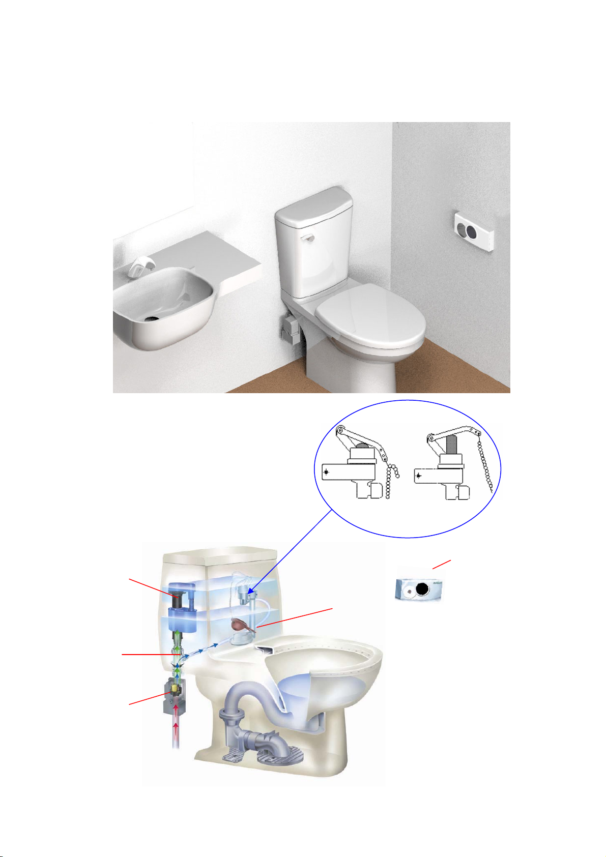
Product Display
Inside Parts
Fill ale
ater Pipe
Open
Solenoid ale
Sensor
ater Pup
Close
Flus ale
1

Features
Te inrared sensor allos ands-ree lusing ensuring giene and a bacteria-ree enironent
utoatic ands-ree lusing unction is especiall beneicial to te andicapped elderl inired and
oung cildren
Te sensor is poered b 4 batteries so tere is no need or a all outlet It is not liited b an oltage
reuireents and tere is no danger o electric soc Under noral operating conditions batter lie
goes beond 1 ear
Designed itout using an electronic parts or electric iring inside te tan It also eans less probles and
a longer lie or eer Sart Toilet
ireless sensor as installation
Fleible installation its ost tan designs It can be used it id to standard eigt ater tans and all
standard toilet bols It can be installed on ne Cs or it can be used to upgrade eisting Cs
Can be used bot or coercial and residential restroos
Specifications
Power Supply
Sensor Unit 4 laline Tpe atteries
Solenoid Valve Assembly 4 laline Tpe atteries
atterie 2 plus ear100 lusesda
Poer Consuption 3 or less
o atter arning Flases on D
SensorTpe Inrared
eoteTpe F ireless eote Control315M
Sensor ange 5 ~ 10 cm
Flus Tie dustable
Flus olue 9 liter adustable
Mecanical ie Oer 500000 luses
ater Inlet Pipe ore PF12
pplicable ater Pressure 05 gc2
pplicable Tans id to standard eigt ater tan it lus
andle installed on te ront
2

Parts ist
Filter Unitt1
Screst2
Pegt1 in Cain Clipst1
ncorst2Code-Matcing Toolt1
laline Tpe atteriest
Sensor Unit t1 Solenoid ale Unit t1 Fill ale Unitt1
ater Connectort1 PC Tubet1 ater Pup Unitt1
Fleible Tubet1
3
Operation
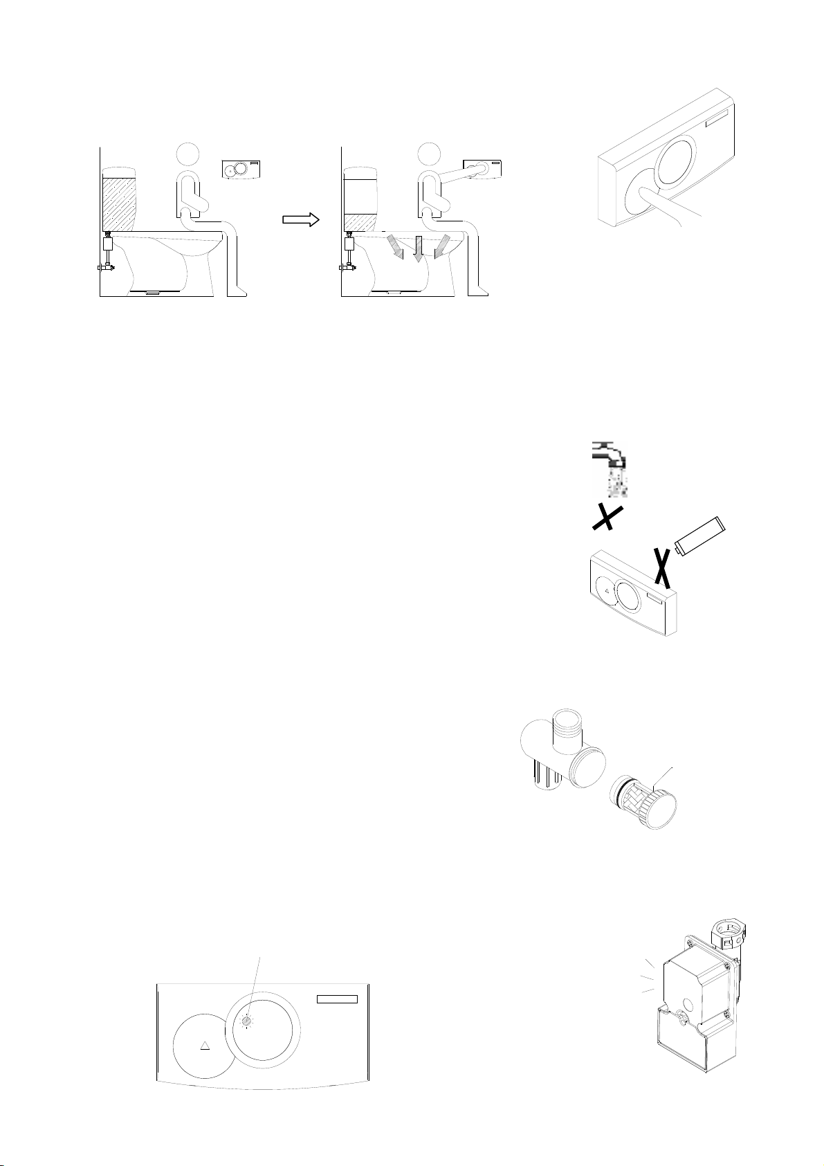
. When the user's hand approach the detection zone, the sensor sends a signal to activate the solenoid valve
which lifts the flapper and flushes the toilet.
. Electronic manual button gives users the option of flushing the toilet by simply pressing the button.
Care and Cleaning Instructions
1 eep te displa panel clean at all ties to preent sensor unction ailure
2 Do not place ea obects or cigarette butts on te casing
3 Do not spra ater or as te casing it igl concentrated
ceical cleaners Tis a result in sort-circuiting or
corrosion. Use mild soap and water , then wipe dry with a soft
clean cloth after washing.
4. Clean Filter Screen:
Poor water quality will result in obstructed and reduced water flow.
To clean the filter screen do the following:
1Turn o ater suppl
2. Remove the filter screen.
3. Wash the screen with clean water and re-insert.
5. Replace Batteries
Need to replace batteries when
1 The red light on the sensor unit flashes
2 The solenoid valve "BEEPS" continuously.
Note: Replace with four AA batteries for either sensor unit or solenoid valve assembly
Filter Screen
Beep
Red light flashes
cid
4
Installation Instructions
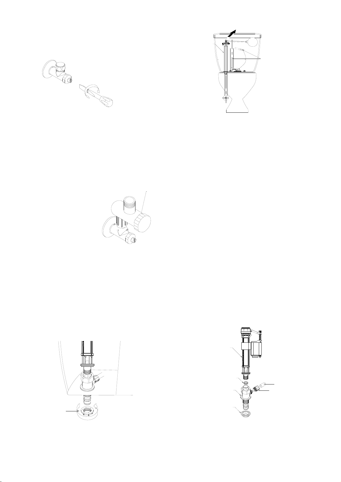
1. Close control stop.See Figure (1).
Fig.1 Fig.2
2. Remove the fill valve unit and its connecting pipe.See Figure(2).
(The flush valve unit remains in place)
3. Install the filter unit to the control stop .See Figure(3).
Fig.3
4. Assemble the fill valve unit and water connector as illustrated in Figure(4).
5. Lock the PVC tube to the water connector with a nut provided.See Figure(4)
6. Install the fill valve unit in the tank as illustrated
in Figure(5). Secure it with a nut provided.
Fig.5 Fig.4
Flush Valve Unit
Fill Valve Unit
Filter Unit
Nut
Nut
PVC Tube
Fill Valve Unit
Rubber Gasket
Rubber Gasket
Water Connector
5

7. Remove the cover of the battery case on solenoid valve assembly as illustrated in Figure(6).
Install 4Alkaline Type AA batteries. Secure the cover back with a screw.
Fig.6
8. Install the flexible tube into the solenoid valve unit.See Figure(7)
Install the combined parts into the water connector.See Figure(8) Fig
Fig.7
9. When positioned properly, secure it with the peg. See Figure(9)
Fig.9
10. Install the flexible tube to the filter unit. (DO NOT bend the tube.).See Figure(10)
Fig.10
Solenoid Valve Unit
Peg
Flexible Tube

11. Install water pump to the top end of the flush valve . Adjust to a proper height then tighten
with a butterfly nut. See Figure(11)
Fig.11
12. Insert the PVC tube to the water inlet of the water pump unit. Secure it with a nut.
See Figure(11.12)
Fig.12
13. Install the link chain as illustrated in Figure(13 )
Fig.13
Correct Installation Too short Too long
(Flapper can not close) (Flapper can not open)
14. Remove the cover of the battery case on the back of the sensor unit. Install 4 Alkaline Type AA
batteries. Secure the cover back with screws. See Figure(14)
Fig.14
Water Pump
Nut
PVC Tube
Overflow Pipe
Screw
Butterfly Nut

15. Mount sensor unit onto the wall as illustrated in Figure(15)(16).Locate it on the side wall.
(See P.11 for instructions when using double sided tape for installation.)
Fig.15
Screw and Anchor Option. See Figure(15)
Using a 1/4” drill bit, drill two holes in their proper positions.
Install the bracket on the wall. Secure with anchors and screws.(included)
Insert the sensor unit onto the bracket.(Place the sensor unit at the bottom of the bracket and slightly
push to fit in the bracket.) Secure it with two screws on the bottom of the sensor unit.
To locate correct position for sensor unit on side wall.See Figure (16).
Fig.16 Unit
Drill two holes
Bracket
Sensor Unit
W.L

Tests and dustents
1. Open control stop when finished installation. Turn on the water. As the water fills in the tank. Check the
connecting points. Make certain no leaking occurs.
2. Observe water as it fills the tank. Make certain the water stops when it reaches the preset water level.
( Make sure no leaking occurs.) The flush volume varies depending on the level of water. Adjust the
water level with the switch on top of the fill valve unit. Clockwise to increase the level.
Counterclockwise to decrease the level. ( Adjust only if necessary.)
3. For courtesy flush, press the manual button on the sensor unit. When the sensor senses a user in
the detection zone for 5 seconds, the sensor sends a signal to the Solenoid Valve to automatically
operate flushing after the user leaves the detection zone. Make sure the arm of the water pump doesn't
touch the tank lid when it's rising.( See the instructions on step 11) Also, make certain the remaining
manual flush handle works properly and no interference occurs among the parts inside the tank while
operating the flushing mechanism.
Water level adjustment
- ater eel don
ater leel up
9
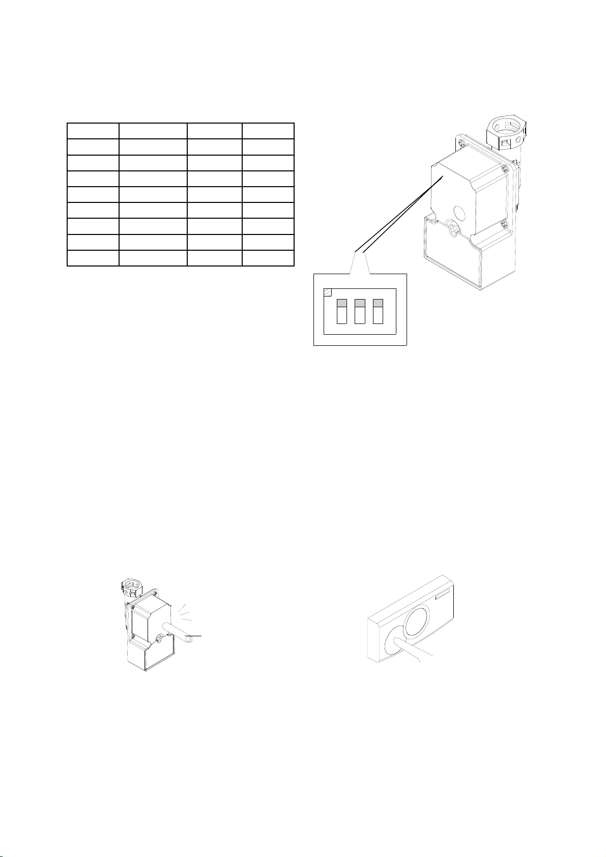
4. Adjust flushing time:
Since the closet is Incomplete flushing , please refer to the chart to adjust the appropriate flush time
and obtain an optimum flushing effect.(Adjust only if necessary)
SW1 SW2 SW3 FLUSH TIME
OFF OFF OFF 1 SEC
OFF OFF ON 2 SEC
OFF ON OFF 3 SEC
OFF ON ON 4 SEC
ON OFF OFF 5 SEC Factory setting
ON OFF ON 6 SEC
ON ON OFF 7 SEC
ON ON ON 8 SEC
Cautions
Prior to installation. Make certain the code on the solenoid valve
matches the code on sensor unit. If not, do as follows:
Step1: Find the code matching tool for matching numbers. Press the tool on the specification
tag on the solenoid valve for 1 second. Listen for "BEEP".
Step2: Press the manual button within 5 seconds right after step 1. Then the numbers will be
automat
i
ca
ll
y reset.
Code-matching tool
Beep
Tie d
123
O
S1 S2 S3
10

Troubleshooting
Light doesn't turn on, 1. No batteries installed in the sensor unit or not 1. Replace batteries
The toilet doesn't flush installed properly
after sensing process 2. Sensor fails 2. Replace sensor unit
Light flashes on sensor unit Low battery in the sensor unit Replace batteries
1. Water turned off or filter obstructed 1. Turn on the water or clean the filter
Light turns on after sensing 2. The codes of the sensor unit and solenoid valve 2. Reset the codes of sensor unit and
process, but the toilet unit don't match solenoid valve.(See P.10 under cautions)
doesn't flush 3. No batteries installed in the solenoid valve unit 3. Reinstall or replace batteries
or installed improperly
4. Solenoid valve fails 4. Replace solenoid valve unit
Solenoid valve continuously Low batteries in the solenoid valve unit Replace batteries
beeps
Incomplete flushing 1. Filter obstructed 1. Clean the filter unit
2. Link chain too long(too loose) 2. Check to make sure the link chain is
adjusted properly
Weak water flow 1. Link chain too long(too loose) 1. Check to make sure the link chain is
adjusted properly
2. Water level too low 2. Readjust the tank water level
Water continuously running 1. The water pump lever is stuck or interference is 1. Check to make sure the water pump is
occurring among tank components while working properly without interference
operating. 2. Check to make sure the link chain is
2. Link chain too short(too tight) adjusted properly
3. The solenoid valve fails 3. Replace solenoid valve unit
Problem Cause Solution to Problem
11

Sensor Unit Mounting – Double-Sided Tape Option
Step1. Wipe both the back of the sensor unit and the wall where the sensor unit will be placed. Be sure both
surfaces are clean and dry.
Step2. Peel off the yellow side of the double-sided tape and place it on the back side of the sensor unit as
shown in the illustration. Be sure to press firmly while keeping the tape straight. Check to see if
the bond is even and secure.
Step3. Peel off tape strips and place the sensor unit on the wall. Be sure to press firmly against the wall.
Please note: If you wait 20 to 30 minutes to attach the sensor unit on the wall, the tape will be more adhesive.
12
Table of contents
Popular Toilet manuals by other brands

Swiss Madison
Swiss Madison Monaco SM-1T109 installation instructions

Kohler
Kohler REACH K-3856T-S installation instructions

Sun-Mar
Sun-Mar EXCEL owner's manual

Swiss Madison
Swiss Madison SM-WT514MB installation instructions

Toto
Toto Washlet C110 SW524 instruction manual

Thetford
Thetford Cassette C-402C Instructions for use


Summer
Summer My Size 11520A instruction manual

Amazon
Amazon B07VM9T6Q1 Welcome guide

Porcelanosa
Porcelanosa noken URBAN-C 100239075 N603470043 quick start guide

YitaHome
YitaHome BFTLPT-1004 Assembly instructions

Signature Hardware
Signature Hardware BURWELL BIDET TOILET SEAT installation instructions

Villeroy & Boch
Villeroy & Boch 9M30U101 installation manual