Foley 622 User manual

- ORIGINAL INSTRUCTIONS -
622
AUTO - INDEX
SPIN / RELIEF
REEL MOWER GRINDER
Patent No. 5,321,912
6,010,394 & 6,290,581
6,685,544 & 6,699,103
SERVICE MANUAL
55013 (11-21)

2
- ORIGINAL INSTRUCTIONS -
As manufacturers of sharpening equipment, we want to conrm to you, our customers, our concern for
safety. We also want to remind you about the simple, basic, and common sense rules of safety when using
this equipment. Failure to follow these rules can result in severe injury or death to operators or bystanders.
It is essenal that everyone involved in the assembly, operaon, transport, maintenance, and storage of this
equipment be aware, concerned, prudent, and properly trained in safety. Always use proper shielding and
personal protecve equipment as specied by the manufacturer.
Our current producon machines include, as standard equipment, guards or shields for the grinding wheel,
safety signs, and operator's and service manuals. Never bypass or operate the machine with any of the
guards or safety devices removed or without the proper personal safety equipment.
Operator's Manual
Before operang this grinder, an operator must read and understand all of the informaon in the
Operator's Manual and understand all of the safety signs aached to the product. A person who has not read
or understood the Operator's Manual and safety signs is not qualied to operate the unit. Accidents oen
occur on machines that are used by someone who has not read the Operator's Manual and is not familiar
with the equipment. If you do not have an Operator's Manual or current producon safety signs, contact the
manufacturer or your dealer immediately.
The equipment is designed for one-man operaon. Never operate the equipment with anyone near, or
in contact with, any part of the grinder. Be sure no one else, including bystanders, is near you when you
operate this product.
Following these simple, basic safety rules, as well as others:
• Find and understand all safety signs in the Operator's Manual and on the equipment. This will help
minimize the possibility of accidents and increase your producvity in using this product.
• Be careful and make sure that everyone who operates the grinder knows and understands that it is a very
powerful piece of machinery, and if used improperly, serious injury or death may result.
• The nal responsibility for safety rests with the operator of this machine.
3
- ORIGINAL INSTRUCTIONS -
Safety Message......................................................................................................... 2
Safety Instrucons.................................................................................................... 3 -6
Service Data and Adjustments ................................................................................. 7 -21
Trouble Shoong ...................................................................................................... 22 -39
Parts Diagram ........................................................................................................... 40 - 71
Wiring Diagram ........................................................................................................ 72 - 73
Wiring Schemac...................................................................................................... 74
Read the Operator's Manual before operang this equipment. Keep this manual handy for ready
reference. Require all operators to read this manual carefully and to become acquainted with all
adjustments and operang procedures before aempng to operate the equipment. Replacement
manuals can be obtained from your selling dealer or the manufacturer.
The equipment you have purchased has been carefully engineered and manufactured to provide
dependable and sasfactory use. Like all mechanical products, it will require cleaning and upkeep.
Lubricate and clean the unit as specied in the Operator's Manual. Please observe all safety
informaon in this manual, the Operator's Manual and the safety decals on the equipment.

4
- ORIGINAL INSTRUCTIONS -
13. Follow
instrucons in Service Manual for lubricaon and
prevenve maintenance.
14. or
when changing the grinding wheel.
15.
Make sure the switch is OFF before plugging in the
Grinder.
16. Consult the
manual for recommended accessories. Using improper
accessories may cause risk of personal injury.
17. A guard or other part
that is damaged or will not perform its intended
funcon should be properly repaired or replaced.
18.
Do not leave grinder unl it
comes to a complete stop.
19. Read this manual
carefully. Learn its applicaon and limitaons as well
as specic potenal hazards.
20.
If safety decals become damaged or illegible for any
reason, replace immediately. Refer to replacement
parts illustraons in Service Manual for the proper
locaon and part numbers of safety decals.
21.
1. and in working order.
2.
3.
4. .
Don't use grinder in damp or wet locaons. Machine
is for indoor use only. Keep work area well it.
5. . All visitors should be
kept a safe distance from work area.
6. with padlocks or
master switches.
7. It will do the job
beer and safer if used as specied in this manual.
8. Don't force the Grinder
or an aachment to do a job for which it was not
designed.
9. Wear no loose clothing,
gloves, neckes, or jewelry which may get caught in
moving parts. Nonslip footwear is recommended.
Wear protecve hair covering to contain long hair.
Wear respirator or lter mask where appropriate.
Wear protecve gloves.
10. .
11. Make certain that the
cung unit is securely fastened with the clamps
provided before operang.
12. Keep proper foong and
balance at all mes.

5
- ORIGINAL INSTRUCTIONS -
DO
1. DO always wheels in a
manner.
2. all wheels before
mounng for possible damage.
3. against the
established maximum safe operang speed
marked on wheel.
4. for equal
and correct diameter.
5. when supplied
with wheels.
6. DO be sure is properly adjusted.
7. DO always at
least one-half of the grinding wheel.
8. DO allow to run
at operang speed, with guard in place, for at
least one minute before grinding.
9. DO always or some
type of eye protecon when grinding.
DON'T
1. DON'T use a cracked wheel or one that
or has become damaged.
2. a wheel onto the machine OR
the size of the mounng hole - if wheel won't
t the machine, get one that will.
3. DON'T ever
established for the wheel.
4. DON'T use mounng anges on which the bearing
surfaces
5. the mounng nut excessively.
6. DON'T grind on the (see
Safety Code B7.2 for excepon).
7. DON'T start the machine unl the
8. work into the wheel.
9. of a grinding
wheel whenever a grinder is started.
10. so that motor slows
noceably or work gets hot.
generated by grinding and cung operaons. Exposure to dust may cause
respiratory ailments. Use approved NIOSH or MSHA respirators, safety glasses or face shields, and protecve
clothing. Provide adequate venlaon to eliminate dust, or to maintain dust level below the Threshold Limit
Value for nuisance dust as classied by OSHA.

6
- ORIGINAL INSTRUCTIONS -
IMPORTANT GROUNDING INSTRUCTIONS
MANUAL
This is the Electrical Hazard Symbol. It indicates that
inside the
enclosure of this product. TO REDUCE THE RISK OF
FIRE OR ELECTRIC SHOCK, do not aempt to open the
enclosure or gain access to areas where you are not
instructed to do so.

7
- ORIGINAL INSTRUCTIONS -
This Service Manual is designed for technicians who have the necessary mechanical and electrical knowledge and skills
to reliably test and repair the 622 Spin/Relief Grinder. For those without the background, service can be arranged
through your local distributor.
This secon presumes that you are already familiar with the normal operaon of the grinder. If not, you should read
the Operator's Manual or do the servicing in conjuncon with someone who is familiar with its operaon.
Persons without the necessary knowledge and skills should not remove any panels or shields, or aempt any internal
troubleshoong, adjustments, or parts replacement.
If you have quesons not answered in this manual, please contact your distributor.
Throughout this manual we refer to torque requirements
as "rmly ghten" or the like. For more specic torque
values, refer to the informaon below.
Refer to the table at the right.
Use the Grade 2 values in the table at the right.
Use the Grade 8 values in the table at the right.
No. 6 screws: 11 in.- lbs (0.125kg - m)
No. 8 screws: 20 in. - lbs (0.23 kg - m)
No. 10 screws: 32 in. - lbs (0.37 kg - m)
6 -lbs 9 -lbs 13 -lbs
thread (0.8 kg-m) (1.25 kg-m) (1.8 kg-m)
11 -lbs 18 -lbs 28 -lbs
thread (1.5 kg-m) (2.5 kg-m) (3.9 kg-m)
19 -lbs 31 -lbs 46 -lbs
thread (2.6 kg-m) (4.3 kg-m) (6.4 kg-m)
30 -lbs 50 -lbs 75 -lbs
thread (4.1 kg-m) (6.9 kg-m) (10.4 kg-m)
45 -lbs 75 -lbs 115 -lbs
thread (6.2 kg-m) (10.4 kg-m) (15.9 kg-m)

8
- ORIGINAL INSTRUCTIONS -
DAILY MAINTENANCE IS SPECIFIED ON PAGE
7 OF THE OPERATOR'S MANUAL AND IS TO BE
PERFORMED BY THE OPERATOR.
LISTED BELOW ARE PERIODIC MAINTENANCE
ITEMS TO BE PERFORMED BY YOUR COMPANY'S
MAINTENANCE DEPARTMENT:
1. Clean the dust tray located under the grinding
wheel area. Use a vacuum or a small broom and
dust pan to clean.
2. Inspect the Poly-V belt on the grinding motor
for cracking and make any necessary adjustments
every three months.
3. Wipe o and lubricate, with never-seize, the
vercal adjustment shas every six months. Run
the arms up and down to coat the working areas of
the sha.
4. Inspect the traverse cog belt for cracking and
defects every three months. Remove any grit or
dust that may aect the funcon of the belt. Adjust
tension if necessary per procedures called out in
the adjustment secon.
5. Clean and lubricate the grinding sha and
traverse shas every 2 to 4 weeks. Follow the
procedure on the next page.
6. Lubricate grinding sha bearing with one shot
of grease once every 2 years. See FIG 2.
9
- ORIGINAL INSTRUCTIONS -
LUBRICATION
STEP 1 – Thoroughly clean all three shas.
STEP 2 – Flood spray all three shas with CRC 3-36 unl the lubricant is dripping o the shas. Do not use
Then run the grinding head assemblies back and forth through their full range
of travel. This will remove the dust and deposits from inside the wheel anges. Repeat if necessary unl
lubricaon is clear of deposits. Clean keyways located on the grinding sha with so brush.
STEP 3 – With a clean rag, wipe o the excess amount of lubricant from the shas. Run the grinding
assemblies through their range of travel and wipe the shas aer each traverse. Repeat unl the shas are
dry to the feel. This completes the lubricaon process.
IMPORTANT:
If the unit will be shut down for an extended period of me, more than four weeks, then the shas and other
appropriate parts of the unit should be ooded with lubricant and that lubricant le in place unl the unit is
brought back into service. When the unit is brought back into service the full lubricaon procedure as stated
above should be repeated.
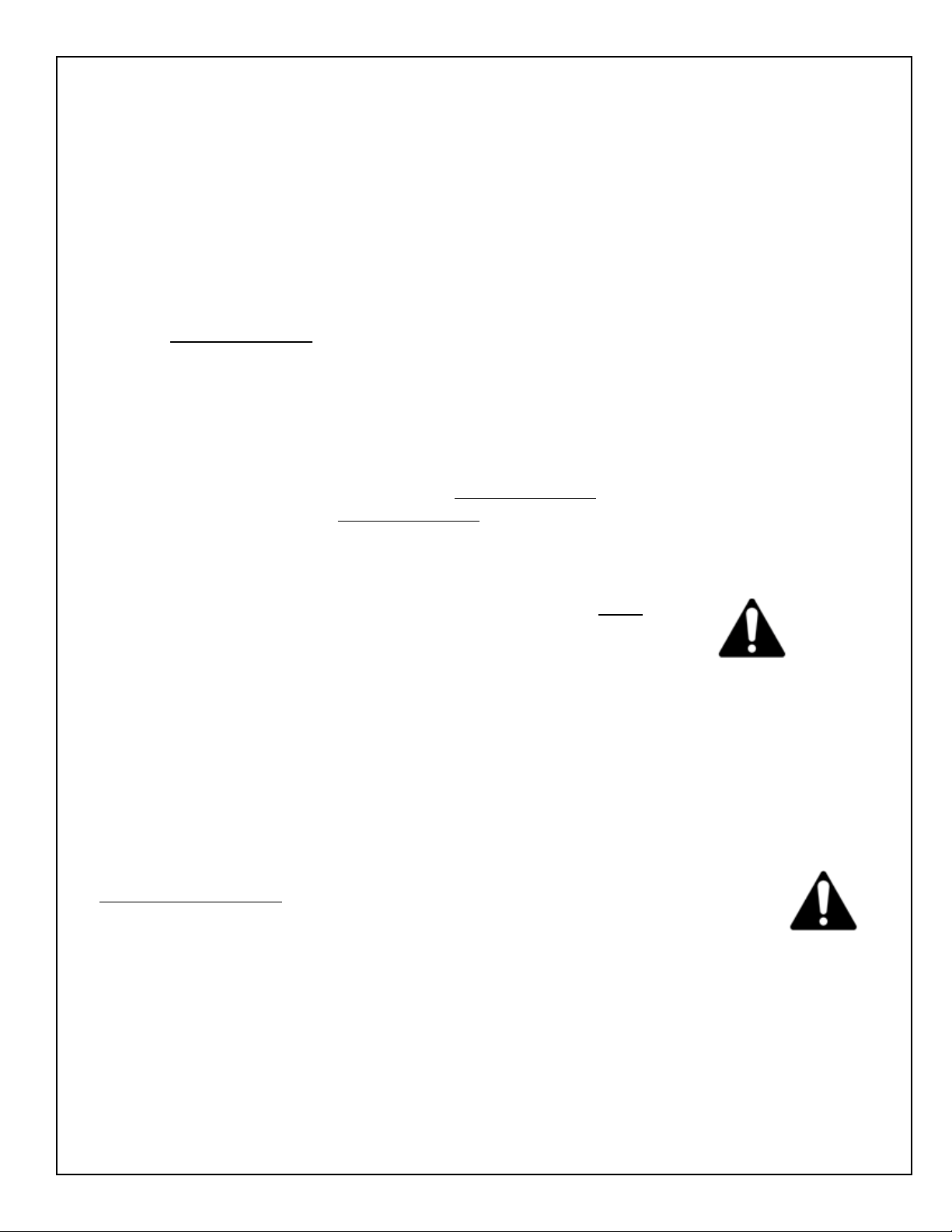
FIG. 3
TRAVERSE
SHAFTS
GRINDING SHAFT
COG BELT
GRINDING SHAFT
BEARING
POLY-V BELT
GRINDING SHAFT
BEARING
10
- ORIGINAL INSTRUCTIONS -
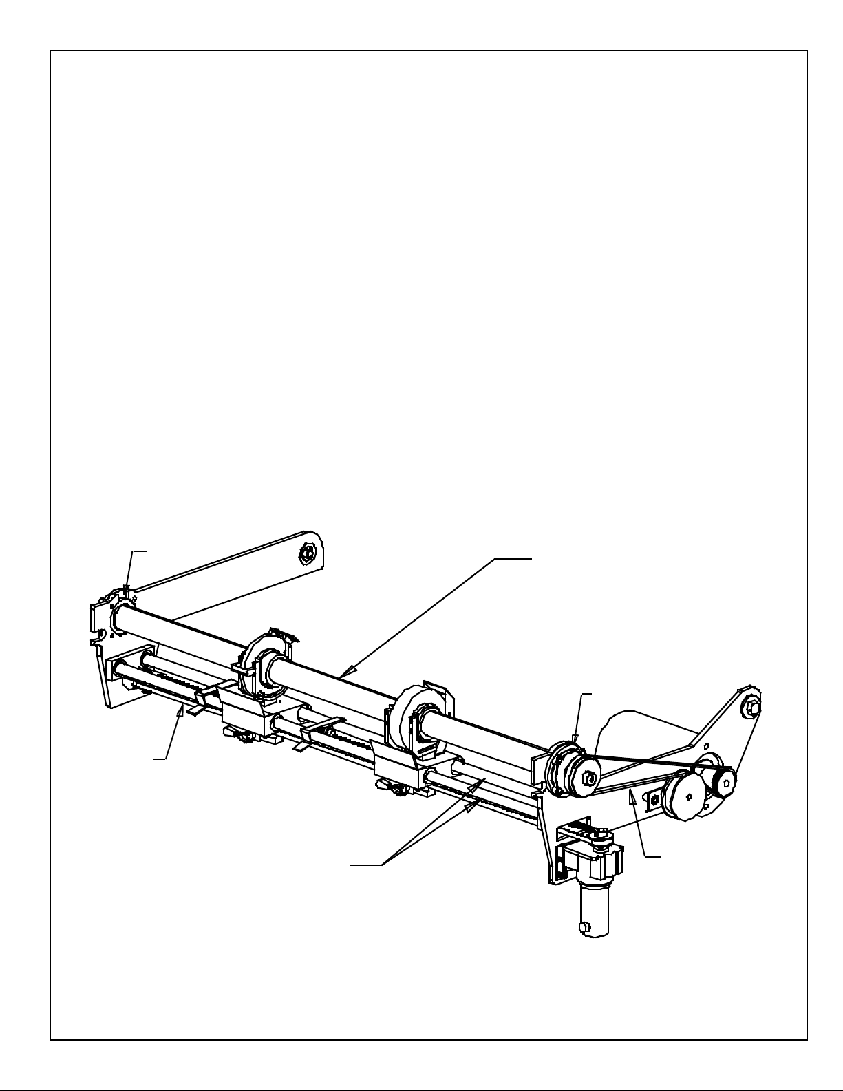
To replace the wheel lower the le side of the
grinding sha and raise the right side.
To remove the le side bearing: rst, loosen the
setscrews on the bearing collar, then remove the four
screws that hold the bearing to the le arm.
Slide the grinding wheel hub assembly(s) o the
sha, taking note of what side the nut is on. Use the
spanner wrench to remove and replace the grinding
wheel(s).
Place the grinding wheel hub assembly(s) back
on the grinding sha. Verify that the spin hub is
located between the spin drive yoke assembly before
lowering the grinding sha.
Reinstall the bearing on the le side of the grinding
sha making sure to t the pilot on the bearing into
arm. Tighten the four mounng screws, and then
ghten the setscrews to the sha.
FIG. 4
BEARING
SPIN NUT
SPIN WHEEL
SPIN FLANGE

11
- ORIGINAL INSTRUCTIONS -
To replace or inspect the grinding motor belt,
remove the right side cover panel. To remove the
belt, pull down on the tensioner pulley.
For the belt to funcon properly the grinding
sha pulley and the grinding motor pulley must
be in line with the tensioner pulley. To adjust the
pulley posion, loosen the setscrews on the pulley.
Locate the belt in the center of the idler pulley.
Measure from the arm to the edge of the belt at
the idler pulley. Adjust the two other pulleys unl
the same measurement is achieved and ghten the
pulley setscrews.
Reinstall the right side cover panel, then run
the grind motor to assure that the belt is not
misaligned. The belt will walk o the pulley if the
system is not aligned properly.
To replace the traverse belt, loosen the nuts on
the le side ulley that are used to tension the belt.
Loosen the screws holding the traverse motor and
lt the boom of the motor out, releasing any
remaining tension on the belt. On the le side
remove the nut from the boom belt tensioning
screw. This will allow the belt to be removed.
Place a new belt on the le pulley, making sure it
is seated properly in the cogged teeth, and replace
the locknut. Feed the new belt through the slot on
the right arm and place on motor pulley. Use the
motor as a lever to apply tension to the new belt.
Tighten motor screws and adjust the tension in
the belt as specied in the BELT TENSION secon.
Adjust the height of the motor pulley if necessary
so the belt is located in the center of the traverse
belt clamp.
Reinstall the le side and right side cover panels,
then test the traverse motor.
FIG. 7
FIG. 6

12
- ORIGINAL INSTRUCTIONS -
CLEANING AND MAINTENANCE GUIDELINES FOR POLYCARBONATE
WINDOWS
Wash polycarbonate windows with a mild dish washing liquid detergent and lukewarm water, using a clean
so sponge or a so cloth. Rinse well with clean water. Dry thoroughly with a moist cellulose sponge to
prevent water spots. Do not scrub or use brushes on these windows. Also, do not use butyl cellosolve in
direct sunlight.
Fresh paint splashes and grease can be removed easily before drying by rubbing lightly with a good grade
of VM&P naphtha or isopropyl alcohol. Aerward, a warm nal wash should be made, using a mild dish
washing liquid detergent soluon and ending with a thorough rinsing with clean water.
Scratches and minor abrasions can be minimized by using a mild automobile polish. Three such products
that tend to polish and ll scratches are Johnson paste Wax, Novus Plasc Polish #1 and #2, and Mirror Glaze
plasc polish (M.G. M10). It is suggested that a test be made on a corner of the polycarbonate window with
the product selected following the polish manufacturer's instrucons.
• DO NOT use abrasive or highly alkaline cleaners on the polycarbonate windows.
• Never scrape polycarbonate windows with squeegees, razor blades or other sharp instruments.
• Benzene, gasoline, acetone or carbon tetrachloride should be used on polycarbonate windows.
• DO NOT clean polycarbonate windows in hot sun or at elevated temperatures.
• Butyl cellosolve, (for removal of paints, marking pen inks, lipsck, etc.)
• The use of masking tape, adhesive tape or lint removal tools works well for liing o old weathered
paints.
• To remove labels, sckers, etc., the use of kerosene, VM&P naphtha or petroleum spirits is generally
eecve. When the solvent will not penetrate scker material, apply heat (hair dryer) to soen the
adhesive and promote removal.
13
- ORIGINAL INSTRUCTIONS -
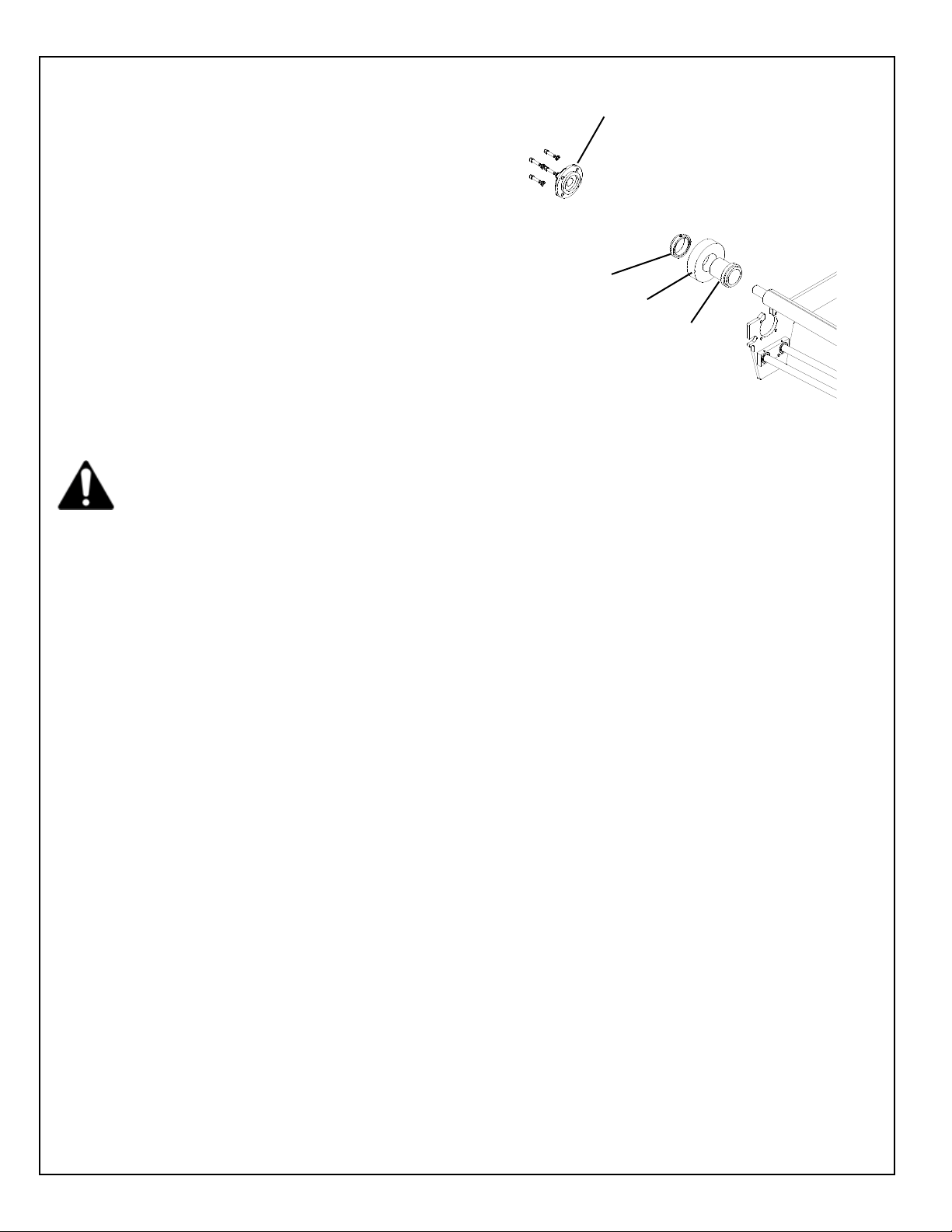
For the proximity switch to perform properly
and reverse the direcon of the grinding head
assembly, the sensor end of the prox must face
toward the head assembly that is in use, and must
be mounted such that it is located past the edge of
the prox holder.
NOTE: The light on the proximity switch acvates
when metal is approximately 3/16" [4.6 mm] from
front of proximity switch.
FIG. 9

14
- ORIGINAL INSTRUCTIONS -
If the spin drive motor is moving during operaon, or
does not move freely into posion, adjust the tension
of the 2 T-Handles. See FIG. 25.
FIG. 25
T-HANDLES
To adjust the tension on the traverse belt, ghten the
screws and nuts located at the le side of the traverse
belt. Tighten the nuts unl the compression springs
measure 3/4" [19mm]. See FIG. 26. If the springs are
not tensioned equally, uneven loading on the traverse
system may cause parts to fail.
DO NOT OVERTIGHTEN. OVERTIGHTENING COULD
DAMAGE THE BELT OR TRAVERSE DRIVE SYSTEM.
If the traverse clamp is slipping during regular
operaon it may be necessary to ghten the clamp. To
ghten, loosen the jam nut on the clamp p. Screw
the p out so there is .10" gap between the p and
the Clamp Support Block. See FIG 27. Lock in place by
ghtening the jam nut against the clamp being careful
not to move the p. Verify the distance between the
clamp p and block is sll .10". The .10" seng allows
slippage in a jam situaon and damage can occur if this
adjustment is set to narrow.
CAUTION SHOULD BE USED AS ADJUSTING THE TIP
WILL AFFECT THE SLIP LOAD AND COULD DAMAGE
THE CLAMP TIP, BELT OR TRAVERSE DRIVE SYSTEM.
FIG. 26
FIG. 27
14
- ORIGINAL INSTRUCTIONS -
ADJUSTMENTS
SPIN MOTOR ADJUSTMENT
If the spin drive motor is moving during operaon, or
does not move freely into posion, adjust the tension
of the 2 T-Handles. See FIG. 25.
FIG. 25
T-HANDLES
TRAVERSE BELT TENSION
To adjust the tension on the traverse belt, ghten the
screws and nuts located at the le side of the traverse
belt. Tighten the nuts unl the comprension springs
measure 3/4" [19mm]. See FIG. 26. If the springs are
not tensioned equally, uneven loading on the traverse
system may cause parts to fail.
DO NOT OVERTIGHTEN. OVERTIGHTENING COULD
DAMAGE THE BELT OR TRAVERSE DRIVE SYSTEM.
TRAVERSE CLAMP FORCE
If the traverse clamp is slipping during regular
operaon it may be necessary to ghten the clamp. To
ghten, loosen the jam nut on the clamp p. Screw
the p out so there is .10" gap between the p and
the Clamp Support Block. See FIG 27. Lock in place by
ghtening the jam nut against the clamp being careful
not to move the p. Verify the distance between the
clamp p and block is sll .10". The .10" seng allows
slippage in a jam situaon and damage can occur if this
adjustment is set to narrow.
CAUTION SHOULD BE USED AS ADJUSTING THE TIP
WILL AFFECT THE SLIP LOAD AND COULD DAMAGE
THE CLAMP TIP, BELT OR TRAVERSE DRIVE SYSTEM.
FIG. 26
FIG. 27
15
- ORIGINAL INSTRUCTIONS -
FIG. 23
The Traverse Drive Control Board has nine
potenometers and four switches as shown
on drawing 6524511 which is included. These
potenometers and switches have been set at the
factory to the posions shown on the drawing.
Also see FIG. 23 and FIG. 24.
The potenometer is factory preset to the minimum
full counterclockwise 8:30 posion. This posion
turns the Acceleraon/Deceleraon o for this
applicaon.
The maximum speed potenometer is preset to
posion for 90 Volts DC output to the traverse motor
at terminals A1 and A2.
The IR Comp control is preset to 3:00 posion. Never
adjust past the 4:30 posion.
Regulaon of the traverse motor may be improved by
slight adjustment of the IR COMP trim pot clockwise
from its factory set posion. Overcompensaon
causes the motor to oscillate or to increase speed
when fully loaded. If you reach such a point, turn
the IR COMP trim pot counterclockwise unl the
symptoms just disappear.
The Reverse Torque seng determines the maximum
current limit for driving the motor in the reverse
direcon. The potenometer is preset to the 10:30
posion. It should not require adjustment.
The Forward Torque seng determines the
maximum current limit for driving the motor in the
forward direcon. The potenometer is preset to
the 10:30 posion. It should not require adjustment.
This motor control board has a potenometer which
must be set for 50 HZ or 60 HZ operaon. For 60 HZ
set to 3:00 posion. For 50 HZ set to 9:00 posion.
The potenometer is factory preset to the minimum
full counterclockwise 8:30 posion.
The tach potenometer is not used in this
applicaon. It should be a the factory seng of 8:30.
This switch is factory preset to the 90 posion for a
90 VDC motor..
This switch is factory preset to the ARM posion.
The lower control board has two switches. Both
switches are factory preset to 115 for 115 VAC
operaon.
Potenometer
Clock Orientaon
Terminal ends (Feet) are always at the 6:00 posion,
no maer how the potenometer is orientated on the board.
FIG. 24
15
- ORIGINAL INSTRUCTIONS -
CONTROL BOARD POTENTIOMETER ADJUSTMENTS
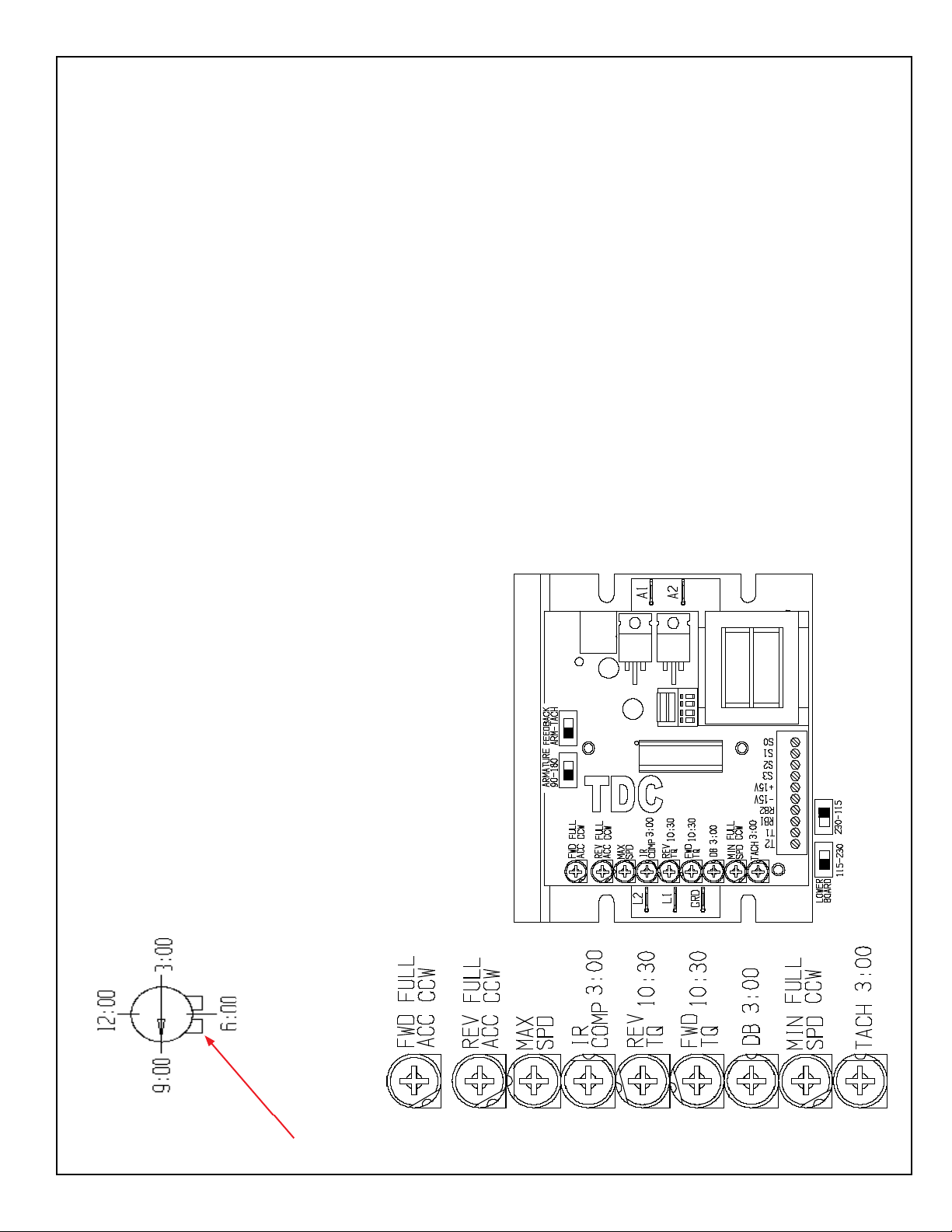
FIG. 23
TRAVERSE DRIVE CONTROL BOARD (TDC)
The Traverse Drive Control Board has nine
potenometers and four switches as shown
on drawing 6524511 which is included. These
potenometers and switches have been set at the
factory to the posions shown on the drawing.
Also see FIG. 23 and FIG. 24.
Fwd Accel & Rev Accel---FWD ACC & REV ACC
The potenometer is factory preset to the minimum
full counterclockwise 8:30 posion. This posion
turns the Acceleraon/Deceleraon o for this
applicaon.
Maximum Speed---MAX SPD
The maximum speed potenometer is preset to
posion for 90 Volts DC output to the traverse motor
at terminals A1 and A2.
IR Compensaon---IR COMP
The IR Comp control is preset to 3:00 posion. Never
adjust past the 4:30 posion.
Regulaon of the traverse motor may be improved by
slight adjustment of the IR COMP trim pot clockwise
from its factory set posion. Overcompensaon
causes the motor to oscillate or to increase speed
when fully loaded. If you reach such a point, turn
the IR COMP trim pot counterclockwise unl the
symptoms just disappear.
Rev Torque---REV TQ
The Reverse Torque seng determines the maximum
current limit for driving the motor in the reverse
direcon. The potenometer is preset to the 10:30
posion. It should not require adjustment.
Fwd Torque---FWD TQ
The Forward Torque seng determines the
maximum current limit for driving the motor in the
forward direcon. The potenometer is preset to
the 10:30 posion. It should not require adjustment.
Deadband---DB
This motor control board has a potenometer which
must be set for 50 HZ or 60 HZ operaon. For 60 HZ
set to 3:00 posion. For 50 HZ set to 9:00 posion.
Minimum Speed---MIN SPD
The potenometer is factory preset to the minimum
full counterclockwise 8:30 posion.
Tach---TACH
The tach potenometer is not used in this
applicaon. It should be a the factory seng of 8:30.
Armature Switch---ARMATURE 90-180
This switch is factory preset to the 90 posion for a
90 VDC motor..
Feedback Switch--- FEEDBACK ARM-TACH
This switch is factory preset to the ARM posion.
The lower control board has two switches. Both
switches are factory preset to 115 for 115 VAC
operaon.
Potenometer
Clock Orientaon
Terminal ends (Feet) are always at the 6:00 posion,
no maer how the potenometer is orientated on the board.
FIG. 24
15
- ORIGINAL INSTRUCTIONS -
CONTROL BOARD POTENTIOMETER ADJUSTMENTS
FIG. 23
TRAVERSE DRIVE CONTROL BOARD (TDC)
The Traverse Drive Control Board has nine
potenometers and four switches as shown
on drawing 6524511 which is included. These
potenometers and switches have been set at the
factory to the posions shown on the drawing.
Also see FIG. 23 and FIG. 24.
Fwd Accel & Rev Accel---FWD ACC & REV ACC
The potenometer is factory preset to the minimum
full counterclockwise 8:30 posion. This posion
turns the Acceleraon/Deceleraon o for this
applicaon.
Maximum Speed---MAX SPD
The maximum speed potenometer is preset to
posion for 90 Volts DC output to the traverse motor
at terminals A1 and A2.
IR Compensaon---IR COMP
The IR Comp control is preset to 3:00 posion. Never
adjust past the 4:30 posion.
Regulaon of the traverse motor may be improved by
slight adjustment of the IR COMP trim pot clockwise
from its factory set posion. Overcompensaon
causes the motor to oscillate or to increase speed
when fully loaded. If you reach such a point, turn
the IR COMP trim pot counterclockwise unl the
symptoms just disappear.
Rev Torque---REV TQ
The Reverse Torque seng determines the maximum
current limit for driving the motor in the reverse
direcon. The potenometer is preset to the 10:30
posion. It should not require adjustment.
Fwd Torque---FWD TQ
The Forward Torque seng determines the
maximum current limit for driving the motor in the
forward direcon. The potenometer is preset to
the 10:30 posion. It should not require adjustment.
Deadband---DB
This motor control board has a potenometer which
must be set for 50 HZ or 60 HZ operaon. For 60 HZ
set to 3:00 posion. For 50 HZ set to 9:00 posion.
Minimum Speed---MIN SPD
The potenometer is factory preset to the minimum
full counterclockwise 8:30 posion.
Tach---TACH
The tach potenometer is not used in this
applicaon. It should be a the factory seng of 8:30.
Armature Switch---ARMATURE 90-180
This switch is factory preset to the 90 posion for a
90 VDC motor..
Feedback Switch--- FEEDBACK ARM-TACH
This switch is factory preset to the ARM posion.
The lower control board has two switches. Both
switches are factory preset to 115 for 115 VAC
operaon.
Potenometer
Clock Orientaon
Terminal ends (Feet) are always at the 6:00 posion,
no maer how the potenometer is orientated on the board.
FIG. 24
16
- ORIGINAL INSTRUCTIONS -
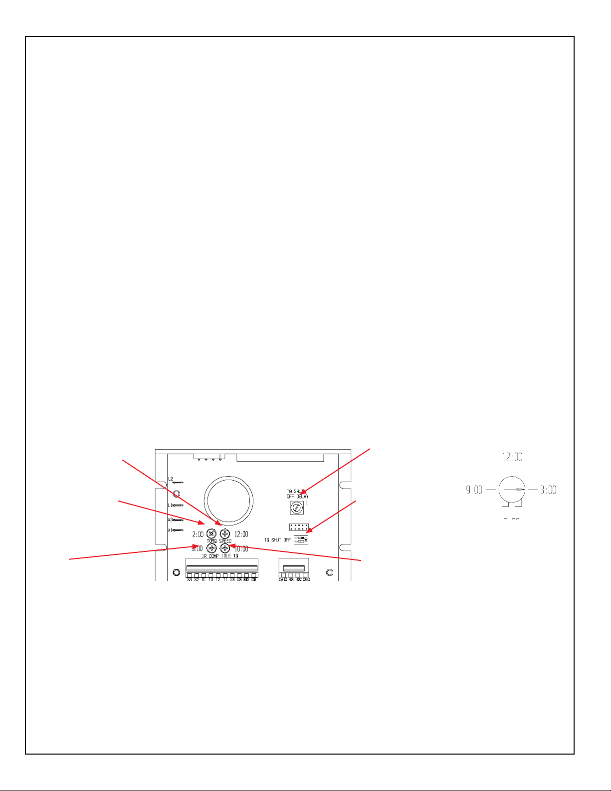
FIG. 18
SPIN TORQUE POT
(TORQ) 2:00
IR COMP
POT
9:00
IDLE TORQUE
POT (ITP)
10:00
RELIEF SPEED
POT (SPEED) 12:00
SWITCH 1
SET TO OFF
DELAY SET
TO 1
Potenometer Clock
Orientaon
SPIN DRIVE CONTROL BOARD (SDC)
The Spin Drive Control Board has four potenometers, two switches and one dial as shown on FIG. 17. These
potenometers,switches and dial have been set at the factory to the posions shown on FIG. 17.
I
The Spin Torque Potenometer (STP) and the Spin Speed Pot (SSP) interact with each other. The (STP) is
located on the spin board as remote torque preset at 2:00 for torque seng. See FIG. 17. The (SSP) is located
on the control panel and is for spin speed adjustment.
Spin Torque Pot (STP) controls maximum torque allowable in the spin grinding cycle only. This should never
be adjusted past the 3:00 posion. If the reel does not turn, check that the reel is free turning by hand
spinning with the power OFF and the spin drive disconnected.
The Spin Speed Pot (SSP) controls reel spin speed, adjust as required. This controls the spin drive speed for
spinning the reel.
The IR Compensaon Pot is factory set at 9:00. Regulaon of the spin or relief grind spin motor
may be improved by a slight adjustment of the IR COMP Pot clockwise from its factory-set posion.
Overcompensaon causes the motor to oscillate or to increase speed when fully loaded. If you reach such a
point, turn the IR COMP Pot counterclockwise unl symptoms just disappear.

17
- ORIGINAL INSTRUCTIONS -
This Electrical Troubleshoong secon is designed for technicians who have the necessary electrical
knowledge and skills to reliably test and repair the ACCU-Touch electrical system. For those without that
background, service can be arranged through your local distributor.
This manual presumes that you are already familiar with the normal operaon of the grinder. If not, you
should read the Operator's Manual, or do the servicing in conjuncon with someone who is familiar with its
operaon.
Persons without the necessary knowledge and skills should not remove the control box cover or aempt any
internal troubleshoong, adjustments, or parts replacement.
If you have any queson not answered in this manual, please call your distributor. They will contact the
manufacturer if necessary.
All wires on the ACCU-Master have a wire label at each end for assembly and troubleshoong. The wire
label has a code which tells you wiring informaon. The rst set of two or three numbers are the Foley wire
number. The next group of leers or numbers are the code for the component to which the wire aaches.
Example: RT1 for Relay Terminal 1. The last set of numbers or leers is the name of the terminal on the
component to which the wire aaches.
To insert or remove a wire from the terminal block, insert a small
screw driver into the square hole. Then insert or remove wire
from the round hole. Remove screwdriver to lock the wire in
place.
Note the square hole can also be used when checking for voltages.
The probe p of the mulmeter can be inserted into the square
hole to take readings.
FIG. 28
18
18
4
12
91
13
5
8
7
10
14
4
32
11
6
- ORIGINAL INSTRUCTIONS -
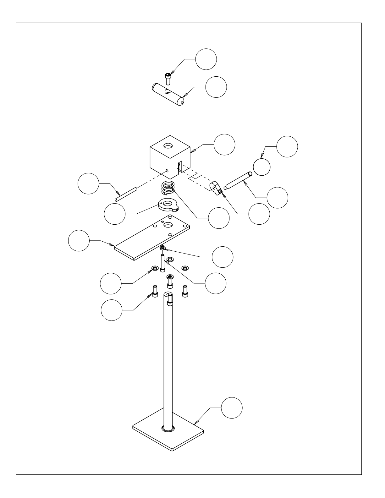
6339541 REAR CLAMP ASSEMBLY
- ORIGINAL INSTRUCTIONS -

19
- ORIGINAL INSTRUCTIONS -
1..................... 09351......................... KNOB - BALL 1.18 OD x 3/8-16F (B27)
2..................... B252431..................... 1/4-28 x 1.5 SOCKET HEAD CAP SCREW FULL THREAD
3..................... K311501..................... 5/16 LOCKWASHER SPLIT
4..................... B311211..................... 5/16-18 x 3/4 SOCKET HEAD CAP SCREW
5..................... H252807 .................... PIN - DRIV LOC .25 D x 1.75 LG
6..................... J252100 ..................... JAM NUT 1/4-28
7..................... 3706207..................... COMPR SPRING .84 ID X .88 LG
8..................... 6339160..................... CLAMP BAR
9..................... 6339161..................... CLAMP HOUSING
10................... 6339163..................... CLAMP RING
11................... 6339164..................... LEVER HANDLE
12................... 6339165..................... BASE HANDLE
13................... 6339212..................... CAM LOCK
14................... 6339540..................... REAR CLAMP WELDMENT
20
20
3
4
10
10
18
18
26
26
39
43
55
63
60
27
27
57
66
8
66
25
4
13
20
16
26
12
17
26
30
44
46
47
48
58
61
62
4
24
25
42
52
41
18
59
45
22
2
23
4
33
15
1
23
14
5
21
24
25 31
32
3437
38
50
54
5
25
36
28
35
51
27 9
11
53
28 35
28
27
19
53
64
65
67
23
15
23
67
56
3
18
4
33
45
- ORIGINAL INSTRUCTIONS -
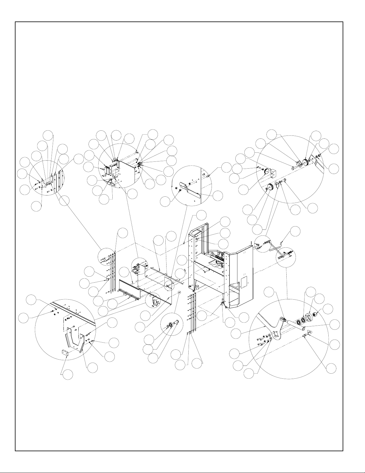
6339545 REAR GUARD DOOR ASSY.
- ORIGINAL INSTRUCTIONS -
Popular Lawn Mower manuals by other brands


Gude
Gude Big Wheeler 560 MEGA Translation of the original instructions

Country Clipper
Country Clipper 1800M Safety instructions and operation manual

SaMASZ
SaMASZ KDTC 260 Operator's manual

VITO GARDEN
VITO GARDEN VIMR1400 instruction manual

McCulloch
McCulloch M55H53HW instruction manual

Husqvarna
Husqvarna TC 242 Euro instruction manual


