Force Computers SPARC/CPU-5TE User manual

FORCE COMPUTERS Inc./GmbH
All Rights Reserved
This document shall not be duplicated, nor its contents used
for any purpose, unless express permission has been granted.
Copyright by FORCE COMPUTERS
SPARC/CPU-5TE
Installation Guide
P/N 203739 Edition 5.0
February 1999

NOTE
The information in this document has been carefully checked and is believed to be entirely reliable. FORCE COMPUTERS makes no warranty of any kind with
regard to the material in this document, and assumes no responsibility for any errors which may appear in this document. FORCE COMPUTERS reserves the right
to make changes without notice to this, or any of its products, to improve reliability, performance, or design.
FORCE COMPUTERS assumes no responsibility for the use of any circuitry other than circuitry which is part of a product of FORCE COMPUTERS Inc./GmbH.
FORCE COMPUTERS does not convey to the purchaser of the product described herein any license under the patent rights of FORCE COMPUTERS Inc./GmbH nor
the rights of others. All product names as mentioned herein are the trademarks or registered trademarks of their respective companies.
World Wide Web: www.forcecomputers.com
24-hour access to on-line manuals, driver updates, and application notes
is provided via SMART, our SolutionsPLUS customer support program
that provides current technical and services information.
Headquarters
The Americas Europe Asia
FORCE COMPUTERS Inc.
2001 Logic Drive
San Jose, CA 95124-3468
U.S.A.
Tel.: +1 (408) 369-6000
Fax: +1 (408) 371-3382
Email [email protected]
FORCE COMPUTERS GmbH
Prof.-Messerschmitt-Str. 1
D-85579 Neubiberg/München
Germany
Tel.: +49 (89) 608 14-0
Fax: +49 (89) 609 77 93
Email [email protected]
FORCE COMPUTERS Japan KK
Miyakeya Building 4F
1-9-12 Hamamatsucho
Minato-ku, Tokyo 105
Japan
Tel.: +81 (03) 3437 3948
Fax: +81 (03) 3437 3968
Email [email protected]

FORCE COMPUTERS Page i
CPU-5TE Installation Guide Table of Contents
Table of Contents
Getting Started
1.1 Caution............................................................................................................................................ 1
1.2 Location Diagram of the SPARC CPU-5TE Board........................................................................ 1
1.3 Before Powering Up ....................................................................................................................... 4
1.3.1 Default Switch Settings ................................................................................................... 4
1.3.2 Memory Module MEM-5................................................................................................ 8
1.4 Powering Up................................................................................................................................... 9
1.4.1 VME Slot-1 Device ......................................................................................................... 9
1.4.2 VMEbus SYSRESET ...................................................................................................... 9
1.4.2.1 SYSRESET Input ........................................................................................... 9
1.4.2.2 SYSRESET Output......................................................................................... 9
1.4.3 Serial Ports....................................................................................................................... 9
1.4.4 RESET and ABORT Key Enable.................................................................................. 10
1.4.5 Front Panel SCSI#1 Termination .................................................................................. 10
1.4.6 P2 SCSI Termination..................................................................................................... 10
1.4.7 Boot Flash EPROM Write Protection ........................................................................... 11
1.4.8 User Flash EPROM Write Protection............................................................................ 11
1.4.9 Reserved Switches......................................................................................................... 11
1.4.10 Floppy Interface or SCSI#2 Availability on P2............................................................. 12
1.4.11 Network Interface Selection (NIS) for Ethernet............................................................ 13
1.4.12 Parallel Port ................................................................................................................... 13
1.5 OpenBoot Firmware ..................................................................................................................... 14
1.5.1 Boot the System............................................................................................................. 14
1.5.2 NVRAM Boot Parameters............................................................................................. 17
1.5.3 Diagnostics .................................................................................................................... 18
1.5.4 Display System Information.......................................................................................... 21
1.5.5 Reset the System............................................................................................................ 22
1.5.6 OpenBoot Help.............................................................................................................. 22
1.6 Front Panel.................................................................................................................................... 24
1.6.1 Features of the Front Panel............................................................................................ 25
1.8 SPARC CPU-5TE Connectors...................................................................................................... 26
1.8.1 Twisted Pair Ethernet Connector Pinout ....................................................................... 27
1.8.2 Serial Port A and B Connector Pinout........................................................................... 28
1.8.3 Keyboard/Mouse Connector Pinout .............................................................................. 30

Table of Contents CPU-5TE Installation Guide
Page ii FORCE COMPUTERS
1.8.4 VME P2 Connector Pinout............................................................................................ 31
1.8.5 The IOBP-10 Connectors .............................................................................................. 32
1.8.5.1 Jumper Setting for IOBP-10......................................................................... 32
1.9 IOBP-DS....................................................................................................................................... 37
1.9.1 Jumper Setting for IOBP-DS......................................................................................... 37
1.9.2 IOBP-DS P2 Connector Pinout ..................................................................................... 38
1.10 How to Determine the Ethernet Address and Host ID.................................................................. 43
1.11 History of the Manual................................................................................................................... 44

FORCE COMPUTERS Page iii
CPU-5TE Installation Guide Table of Contents
List of Figures
Figure 1. Diagram of the CPU-5TE (Top View) ............................................................................... 2
Figure 2. Diagram of the CPU-5TE (Bottom View) ......................................................................... 3
Figure 3. SCSI Termination ............................................................................................................ 10
Figure 4. Floppy or SCSI #2 Availability on P2 ............................................................................. 12
Figure 5. Diagram of the Front Panel .............................................................................................. 24
Figure 6. Twisted Pair Ethernet ....................................................................................................... 27
Figure 7. Serial Ports A and B Connector Pinout ............................................................................ 29
Figure 8. Keyboard/Mouse Connector ............................................................................................ 30
Figure 9. The IOBP-10 .................................................................................................................... 32
Figure 10. The IOBP-DS ................................................................................................................... 37

Table of Contents CPU-5TE Installation Guide
Page iv FORCE COMPUTERS
List of Tables
Table 1. Default Switch Settings...................................................................................................... 4
Table 2. Device Alias Definitions.................................................................................................. 16
Table 3. Setting Configuration Parameters.................................................................................... 17
Table 4. Diagnostic Routines......................................................................................................... 18
Table 5. Commands to Display System Information..................................................................... 21
Table 6. SPARC CPU-5TE Connectors......................................................................................... 26
Table 7. Twisted Pair Ethernet Connector Pinout.......................................................................... 27
Table 8. Serial Port A and B Connector Pinout............................................................................. 28
Table 9. Keyboard/Mouse Connector Pinout................................................................................. 30
Table 10. VME P2 Connector Pinout .............................................................................................. 31
Table 11. IOBP-10 P1 Pinout........................................................................................................... 33
Table 12. IOBP-10 P2 Pinout (SCSI #1) ......................................................................................... 34
Table 13. IOBP-10 P3 Pinout (Floppy)............................................................................................ 35
Table 14. IOBP-10 P5 Pinout (Serial).............................................................................................. 36
Table 15. IOBP-10 Pinout (Ethernet)............................................................................................... 36
Table 16. IOBP-DS J1 Pinout (SCSI #1)......................................................................................... 39
Table 17. IOBP-DS J2 Pinout (SCSI #2)......................................................................................... 40
Table 18. IOBP-DS J3 Pinout (Ethernet #1 - AUI) ......................................................................... 41
Table 19. IOBP-DS J4 Pinout (Serial A and B)............................................................................... 42
Table 20. IOBP-DS J5 Pinout (Keyboard/Mouse)........................................................................... 42
Table 21. History of Manual............................................................................................................ 44

FORCE COMPUTERS Page 1
SPARC/CPU-5TE Installation Guide
1. Getting Started
This Installation Guide provides guidelines for powering up the SPARC/CPU-5TE board. The
Installation Guide, which you have in your hand now, appears both as Section 2 of the SPARC
CPU-5TE Technical Reference Manual and as a stand-alone Installation Guide. The SPARC
CPU-5TE Technical Reference Manual is also available from FORCE COMPUTERS. The
SPARC/CPU-5TE Technical Reference Manual provides a comprehensive hardware and
software guide to your board and is intended for those persons who require complete
information.
1.1 Caution
Please read this Installation Guide before installing the board. Take a moment to examine the
Table of Contents to see how this documentation is structured. This will be of value to you
when looking for specific information in the future.
CAUTION: Do not plug or remove board under power.
1.2 Location Diagram of the SPARC CPU-5TE Board
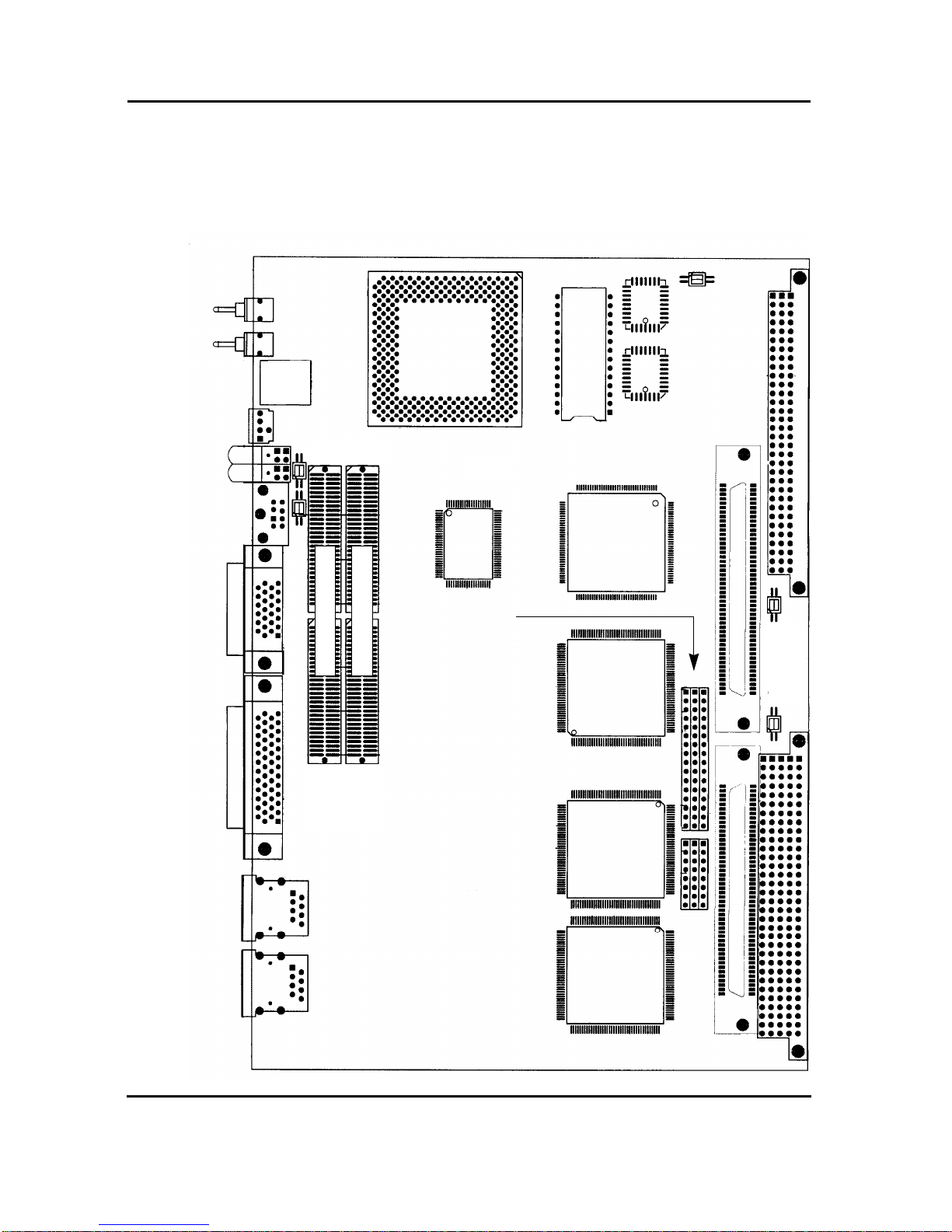
A location diagram showing the important components on the CPU-5TE (top view) appears on
the following page. On the page next to it, there is a location diagram of the CPU-5TE (bottom
view) showing the position of five of the on-board switches.
Installation Guide SPARC/CPU-5TE
Page 2 FORCE COMPUTERS
FIGURE 1. Diagram of the CPU-5TE (Top View)
Reset
Abort
Rotary
Status LEDs
User LEDs
Keyboard
and
Mouse
Serial Port
A and B
SCSI #1
Twisted
Pair
Ethernet 2
Micro
S4-VME
"SLAVIO"
"MACIO"
NCR89C100
"MACIO"
NCR89C100
NCR89C105
RTC/NVRAM
LCA
B2 B3 B1
Ethernet 1
SBus Slot #2 at P4 SBus Slot #1 at P3
SW11
SW10
SPARC-II
SW4
SW6
Boot Flash
J 124
J 125
SW 7
B10 B9 B8
B2, B3, B1
and
B 10, B9, B8
are the sockets for
SCSI #2/Floppy
Switch Matrix
Twisted
Pair
Memory
Lower
(#1)
Upper
(#2)
Memory Module #2
Memory Module #1
7-Segment
Display
#2
#1

FORCE COMPUTERS Page 3
SPARC/CPU-5TE Installation Guide
FIGURE 2. Diagram of the CPU-5TE (Bottom View)
SW8
SW12
SW5
SW13
SW9
Installation Guide SPARC/CPU-5TE
Page 4 FORCE COMPUTERS
1.3 Before Powering Up
Before powering up, please make sure that the default switch settings are all set according to
the table below. Check these switch settings before powering up the SPARC CPU-5TE
because the board is configured for power up according to these default settings. For the
position of the switches on the board, please see the diagrams on the previous two pages.
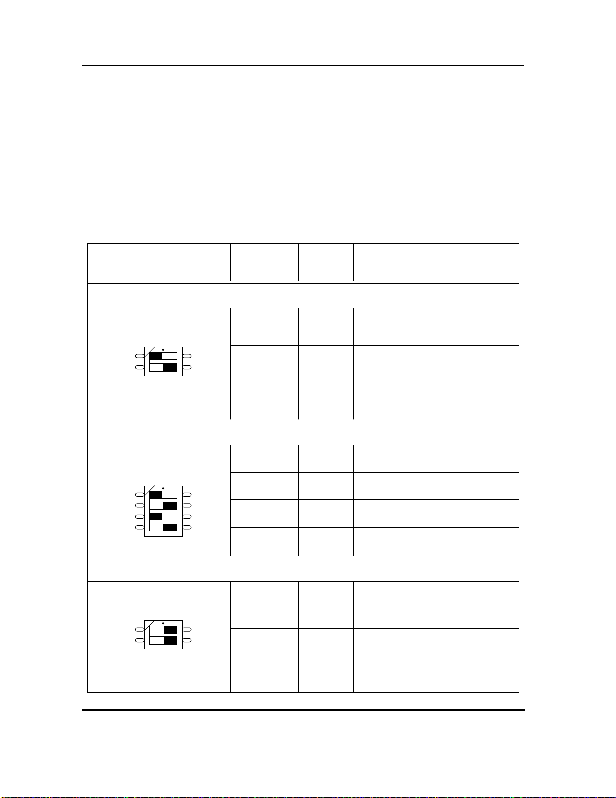
1.3.1 Default Switch Settings
Table 1: Default Switch Settings
Diagram of Switch Switches Default
Setting Function
SWITCH 4
SW4-1 OFF reserved, must be OFF.
SW4-2 ON reserved, must be ON.
SWITCH 5
SW5-1 OFF Test Switch, must be OFF
SW5-2 ON Test Switch, must be ON
SW5-3 OFF SCSI Termination for SCSI # 2 on P2
OFF = Enable, ON = Disable
SW5-4 ON SCSI Termination for SCSI # 1 on P2
OFF = Enable, ON = Disable
SWITCH 6
SW6-1 ON Reset Key Control
ON=Reset Key enable, OFF=Reset Key disable
SW6-2 ON Abort Key Control
ON=Abort Key enable, OFF=Abort Key disable
ON
1
2
ON
1
2
3
4
ON
1
2
FORCE COMPUTERS Page 5
SPARC/CPU-5TE Installation Guide
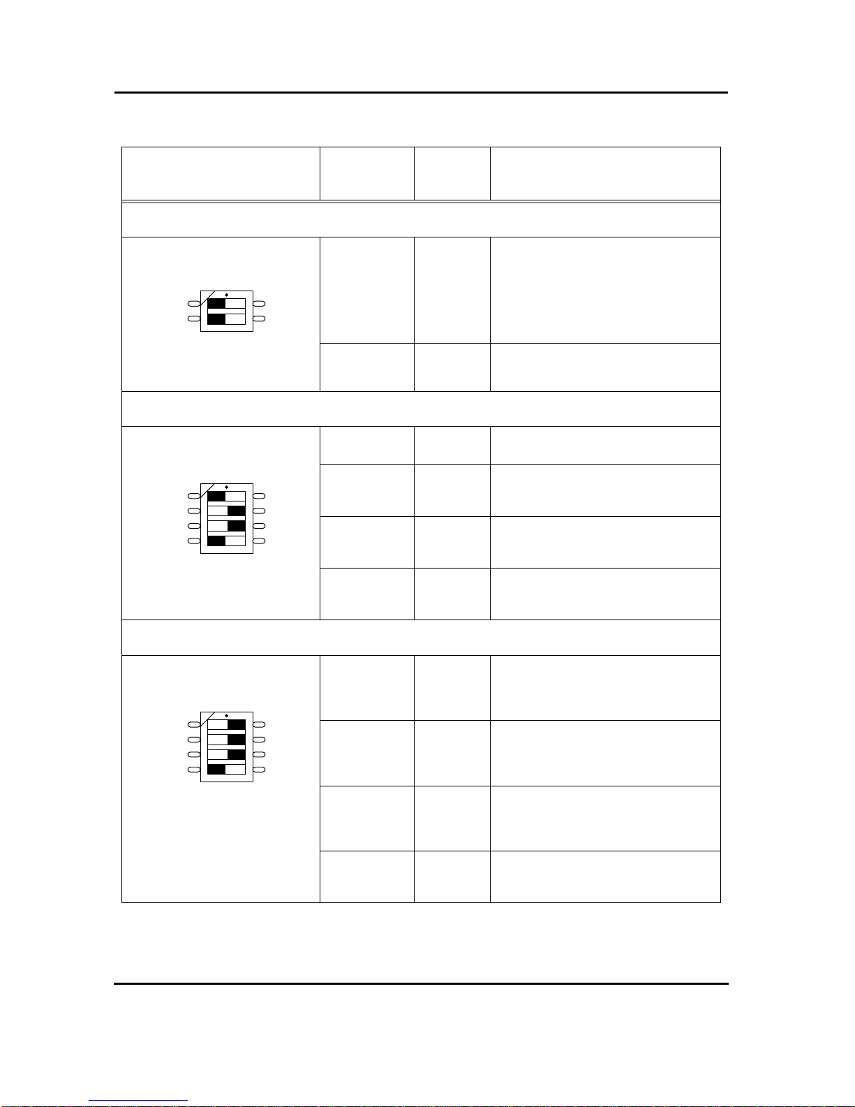
SWITCH 7
SW7-1 OFF SCSI#1 termination for Front Panel
OFF = Automatic (When a connector is plugged
into the front panel SCSI connector, then termi-
nation is disabled. When no connector is
plugged into the front panel SCSI connector,
then termination is enabled.)
ON = disabled
SW7-2 OFF Test Switch, must be OFF
SWITCH 8
SW8-1 OFF Test Switch, must be OFF
SW8-2 ON TRXC on Front Panel Connector for RS-232
ON=Available, OFF=Not Available
(Serial Port B)
SW8-3 ON TRXC on Front Panel Connector for RS-232
ON=Available, OFF=Not Available
(Serial Port A)
SW8-4 OFF TRXC +/- on Front Panel Connector for RS-422
ON=Available, OFF=Not Available
(Serial Port B)
SWITCH 9
SW9-1 ON CTS on Front Panel Connector for RS-232 or
CTS +/- on Front Panel Connector for RS-422
ON=Available, OFF=Not Available
(Serial Port B)
SW9-2 ON RTS on Front Panel Connector for RS-232 or
RTS +/- on Front Panel Connector for RS-422
ON=Available, OFF=Not Available
(Serial Port B)
SW9-3 ON RTS on Front Panel Connector for RS-232 or
RTS +/- on Front Panel Connector for RS-422
ON=Available, OFF=Not Available
(Serial Port A)
SW9-4 OFF TRXC +/- on Front Panel Connector for RS-422
ON=Available, OFF=Not Available
(Serial Port A)
Table 1: Default Switch Settings (cont.)
Diagram of Switch Switches Default
Setting Function
ON
1
2
ON
1
2
3
4
ON
1
2
3
4
Installation Guide SPARC/CPU-5TE
Page 6 FORCE COMPUTERS
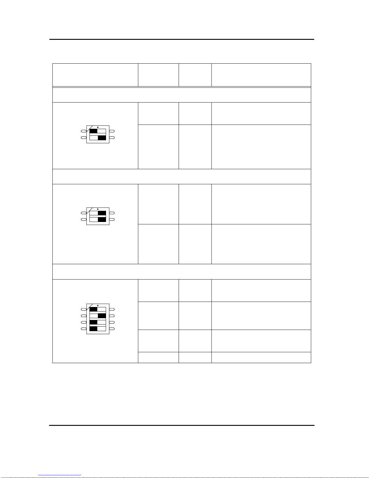
SWITCH 10
SW10-1 OFF Test Switch, must be OFF
SW10-2 ON VMEbus Slot-1 Device
ON = Automatic Slot-1 Device Recognition
OFF = Not Slot-1 Device
SWITCH 11
SW11-1 ON SYSRESET received from VMEbus
ON = VMEbus SYSRESET generates on-board
RESET
OFF = VMEbus SYSRESET does not
generate on-board RESET
SW11-2 ON VMEbus SYSRESET Generation
ON = SYSRESET is driven to VMEbus if board
is Slot-1 Device or during power-up reset
OFF = SYSRESET is not driven to VMEbus
SWITCH 12
SW12-1 OFF RTXC +/- on Front Panel Connector for RS-422
ON=Available, OFF=Not Available
(Serial Port B)
SW12-2 ON CTS on Front Panel Connector for RS-232 or
CTS +/- on Front Panel Connector for RS-422
ON=Available, OFF=Not Available
(Serial Port A)
SW12-3 OFF RTXC +/- on Front Panel Connector for RS-422
ON=Available, OFF=Not Available
(Serial Port A)
SW12-4 OFF Test Switch, must be OFF
Table 1: Default Switch Settings (cont.)
Diagram of Switch Switches Default
Setting Function
ON
1
2
ON
1
2
ON
1
2
3
4

FORCE COMPUTERS Page 7
SPARC/CPU-5TE Installation Guide
CAUTION: To avoid damaging the serial ports, please consider the following regarding
Switch 8, Switch 9 and Switch 12. Do not set the switches (SW8-3 and SW12-4), or (SW9-4
and SW9-3), or (SW12-2 and SW12-3) to ON at the same time and do not set the switches
(SW8-2 and SW8-1), or (SW8-4 and SW9-2), or (SW9-1 and SW12-1) to ON at the same
time!
SWITCH 13
SW13-1 OFF User Flash EPROM write protection
ON = disable, OFF = enable
SW13-2 OFF Boot Flash EPROM write protection
ON = disable, OFF = enable
SW13-3 OFF/ON No function
SW13-4 OFF/ON No function
Table 1: Default Switch Settings (cont.)
Diagram of Switch Switches Default
Setting Function
ON
1
2
3
4

Installation Guide SPARC/CPU-5TE
Page 8 FORCE COMPUTERS
1.3.2 Memory Module MEM-5
It is necessary to install the memory module on the board before powering up. For instructions
on installing the MEM-5, please see the document How to Install MEM-5.
Memory Module # 1 must be installed for power up because it holds configuration
information for booting the board. Memory module # 2 is optional for increasing memory
capacity. For the location of the memory module connectors on the board, please see
“Diagram of the CPU-5TE (Top View)” on page 2.

FORCE COMPUTERS Page 9
SPARC/CPU-5TE Installation Guide
1.4 Powering Up
The initial power up can easily be done by connecting a terminal to ttya (serial port A). The
advantage of using a terminal is that no frame buffer, monitor, or keyboard is used for initial
power up, which facilitates a simple startup.
Please see the chapter “Boot the System” on page 14 for more detailed information on booting
the system.
1.4.1 VME Slot-1 Device
The SPARC CPU-5TE can be plugged into any VMEbus slot; however, the default
configuration automatically detects that the board is a VME slot-1 device, which functions as
VME system controller. To configure your CPU-5TE so it is not a VME slot-1 device, the
default configuration must be changed so that SW10-2 is OFF.
CAUTION: Before installing the SPARC CPU-5TE in a miniforce chassis, please first disable
the VMEbus System Controller function by setting switch SW10-2 to OFF.
1.4.2 VMEbus SYSRESET
1.4.2.1 SYSRESET Input
A SYSRESET received from VMEbus generates an on-board RESET if switch SW11-1 is ON
(default setting). When SW11-1 is OFF, the SYSRESET received from the VMEbus does not
generate an on-board RESET.
1.4.2.2 SYSRESET Output
There are several possible ways for the CPU-5TE to generate a SYSRESET signal to the
VMEbus. One way is when the CPU-5TE is a VMEbus slot-1 device and an on-board local
SBus reset occurs, then the CPU-5TE generates the SYSRESET signal to the VMEbus. A
second way for the SYSRESET signal to be generated is by power-up reset. Power-up reset
occurs by switching on the power. Power-up Reset also occurs when the power monitor
detects power fail or the front panel reset key is toggled.
This SYSRESET signal can be disabled by setting the switch SW11-2 to OFF.
1.4.3 Serial Ports
By default, both serial ports are configured as RS-232 interfaces. The chapter “Default Switch
Settings” on page 4 shows the necessary switch settings for RS-232 operation.
Installation Guide SPARC/CPU-5TE
Page 10 FORCE COMPUTERS
1.4.4 RESET and ABORT Key Enable
To enable the RESET and the ABORT functions on the front panel, set switches SW6-1
(RESET) and SW6-2 (ABORT) to ON. This is the default setting.
1.4.5 Front Panel SCSI#1 Termination
Please note how the SCSI#1 termination works on the front panel. Termination for the SCSI#1
interface is disabled when SW7-1 is ON. When switch SW7-1 is OFF, the termination is set
to automatic termination mode. Automatic termination mode means the respective termination
is disabled when you connect a standard SCSI cable to the connector.
1.4.6 P2 SCSI Termination
Termination for the P2 SCSI#1 is disabled when SW5-4 is ON, and this is the default setting.
Termination for the P2 SCSI#2 is enabled when SW5-3 is OFF, and this is the default setting.
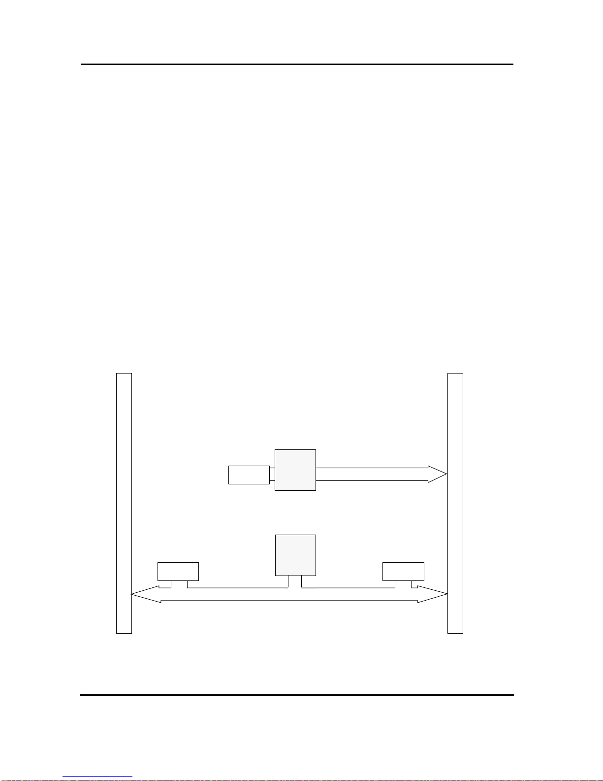
FIGURE 3. SCSI Termination
MACIO
SCSI#1
F
R
O
N
T
P
A
N
E
L
MACIO SCSI#2
#1
#2
SCSI#1
V
M
E
B
u
s
P
2
C
o
n
n
e
c
t
o
r
Termination
SW7-1 controls SCSI#1 termination for Front Panel
OFF = Automatic
ON = Disabled
SW5-3 controls SCSI#2 termination on P2
OFF = Enable
ON = Disabled
OFF = Enable
ON = Disabled
SW5-4 controls SCSI#1
termination on P2
Termination
Termination

FORCE COMPUTERS Page 11
SPARC/CPU-5TE Installation Guide
1.4.7 Boot Flash EPROM Write Protection
Both Boot Flash EPROMs are write protected via the switch SW13-2. When SW13-2 is OFF,
the devices are write protected, and this is the default setting.
1.4.8 User Flash EPROM Write Protection
The optional User Flash EPROMs are write protected via SW13-1. When SW13-1 is OFF, the
User Flash EPROMs are write protected, and this is the default setting.
1.4.9 Reserved Switches
SW5-1, SW5-2, SW7-2, SW8-1, SW10-1 and SW12-4 are reserved for test purposes. SW5-1,
SW7-2, SW8-1, SW10-1 and SW12-4 should always be OFF. SW5-2 should always be ON.
Installation Guide SPARC/CPU-5TE
Page 12 FORCE COMPUTERS
1.4.10 Floppy Interface or SCSI#2 Availability on P2
It is important to understand that the availability of both the floppy and SCSI#2 devices at the
same time is dependent upon the availability of a 5-row P2 connector. When using a 3-row P2
connector, you have the choice of either the floppy or the SCSI#2 on P2. The following
describes how to configure the board for floppy or SCSI#2.
Via a 24-pin configuration switch matrix, it is possible for either the floppy interface or the
SCSI#2 to be available on the VME P2 connector on row C. The default setting enables the
floppy interface via the VME P2 connector, with the configuration switch matrix plugged into
B2/B3 and B10/B9. This means, of course, that by default the SCSI#2 is not available via the
VMEbus P2 connector on row C.
To enable the SCSC#2 via the VME P2 connector, plug the configuration switch matrix in
sockets B3/B1 and B9/B8.
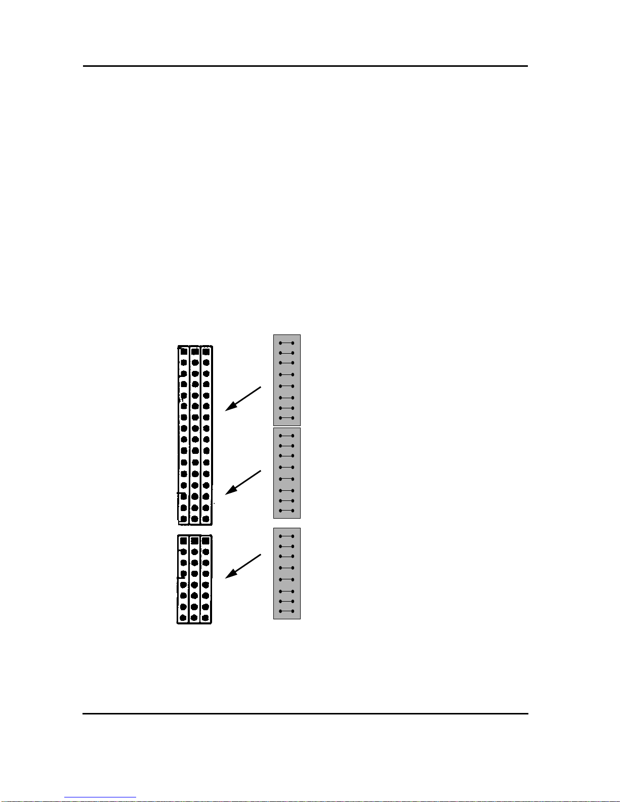
FIGURE 4. Floppy or SCSI #2 Availability on P2
CAUTION: If you use an IOBP-DS, the switch matrix must be located on B3/B1 and B9/B8
in order to route SCSI #2 to P2 row C. If you use an IOBP-10, the switch matrix must be
located on B2/B3 and B10/B9 in order to route the floppy interface to P2 row C.
B2 B3 B1
B10 B9 B8
This 3-piece configuration
switch matrix is used for
choosing either the floppy
interface or SCSI#2.
Plug the interface into
sockets B2/B3 and B10/B9
for the floppy interface.
Or
Plug the interface into
sockets B3/B1 and B9/B8
for the SCSI#2 interface.

FORCE COMPUTERS Page 13
SPARC/CPU-5TE Installation Guide
1.4.11 Network Interface Selection (NIS) for Ethernet
It is important to understand that the Ethernet is selected either via the twisted pair connector
or the AUI (Attachment Unit Interface). When you boot your system and a connection exists
with an AUI network, then the AUI is automatically selected. In other words, when you have
a successful connection with a network, the AUI is used. When you have no connection with
the network, then the twisted pair is selected. This is valid for both Ethernet #1 and
Ethernet #2. The Ethernet#1 channel and the Ethernet#2 channel function independently of
each other. For both Ethernet interfaces there is one Ethernet address. This means that you
don’t have to connect both interfaces to one physical cable.
1.4.12 Parallel Port
The availability of the parallel port is dependent upon the availability of a 5-row P2 connector.
When using a 3-row P2 connector, parallel port is not available.

Installation Guide SPARC/CPU-5TE
Page 14 FORCE COMPUTERS
1.5 OpenBoot Firmware
This chapter describes the use of OpenBoot firmware. Specifically, you will read how to
perform the following tasks.
• Boot the System
• Run Diagnostics
• Display System Information
• Reset the System
• OpenBoot Help
For detailed information concerning OpenBoot, please see the OPEN BOOT PROM 2.0
MANUAL SET. This manual is included in the SPARC CPU-5TE Technical Reference Manual
Set.
1.5.1 Boot the System
The most important function of OpenBoot firmware is booting the system. Booting is the
process of loading and executing a stand-alone program such as the operating system. After it
is powered on, the system usually boots automatically after it has passed the Power On SelfTest
(POST). This occurs without user intervention.
If necessary, you can explicitly initiate the boot process from the OpenBoot command
interpreter. Automatic booting uses the default boot device specified in nonvolatile RAM
(NVRAM); user initiated booting uses either the default boot device or one specified by the
user.
To boot the system from the default boot device, type the following command at the Forth
Monitor prompt.
or, if you are at the Restricted Monitor Prompt, you have to type the following:
ok boot
>b
Table of contents


