Fortress Automotive Security FS-52 System manual

FS-42 and FS-52 Combo Alarm System
INSTALLATIONHANDBOOK:
INTRODUCTION
Congratulationson yourchoiceofaCrimestopper combination alarm&remoteengine starter withDataPort
Technology
Thisinstallationbookisdesignedfortheinstallerorindividualwithanexistingunderstandingof
automotive electricalsystems,along withtheabilitytotestandconnectwires forproperoperation.Toease
installation,wesuggest thatyouREAD THISMANUALbeforebeginningyourinstallation.Thisbookis
providedasaGENERALGUIDELINEandtheinformationcontainedhereinmaydifferfromyourvehicle.
DISCLAIMER:
CrimestopperSecurity Products,Inc.anditsvendorsshallnotbeliableforanyaccidentresultingfromthe
useofthisproduct.Thissystemisdesignedtobeprofessionallyinstalledintoavehicleinwhichall
systemsandassociatedcomponentsareinperfect workingcondition.
TECHNICALSUPPORT(800)-998-6880
Monday-Friday8:00am-4:30pmPacificTime
Website: www.crimestopper.com
CRIMESTOPPERSECURITYPRODUCTS, INC.
1770S. TAPO STREET
SIMI VALLEY, CA.93063
REV 09.2012
Thisdevice complies withFCC Rules part 15. Operationis
subject to thefollowingtwo conditions: 1) Thisdevice may not
causeinterference, and(2) thisdevice must acceptany
interference thatmay be received, includinginterference that
may cause undesired operation.The manufacturer isnot
responsiblefor anyradioor TV interferencecausedby
unauthorized modificationto thisequipment. Such
modificationcouldvoidtheuser'sauthority to operate the
equipment.

2
TABLEOF CONTENTS
Cautions&WarningsandComponentMounting..…..………………………………………………………………………3
Wiring Information….……….…………………………....……………...……………………………………………..……4-10
Shock Sensor …….………….…………………………....……………...……………………………………………..……11
PowerDoor LockWiring, Systems&Diagrams.........……………...….………..…….……..…………...……….……12-14
Tachless, TachReference,TachFinder, TimedCrankModes………..……………………………………………....15-17
DieselGlowPlug Delay………………………………………………………………………………………………...………18
ProgrammableOptions, OptionsReset……….………………………………………………….………….………...…18-26
RemoteTransmitter/ TransceiverProgramming…………………………………......…..…………………...…...…...….27
2-VehicleProgramming.………………………………………………………………………………………………...……..28
AlarmTrigger &RemoteStart Diagnostics……………………………………………………………………….………….29
ManualTransmission Mode……….……………………..………………………………………...…………………...…….30
Antenna Diagram…….…….…….…………………………....……………...……………………………………………..…31
Connector Plugs&Jumper PinDiagram…………….……………………………………………………………………....32
SystemWiring Diagrams&DATAPortDiagram.………………………………………………………….……………33-35
PR PRE-INSTALLATIONCONSIDERATIONS
BEFORE BEGINNING,check all vehiclemanufacturer cautionsandwarnings regardingelectricalservice (AIR BAGS, ABS
BRAKES, ENGINE/ BODYCOMPUTER AND BATTERY).
PLANOUTYOUR INSTALLATION.Youshouldpre-determinethelocationofthe ControlModule(Brain),Valet button,
LED, and Sirenlocations. This willsave time and ease theinstallationprocess.
USE VOLT/OHM METER totest andlocate all connections. Test Lights or LightedProbes couldpossiblydamage a
vehicle’s computersystem or cause anairbag to deploy.
ADDITIONALPARTS,that are not included withthisunit, may be needed for yourparticular vehicle. These items may
include extra relays, Door Lock Interface Modules, or Transponder Override modules.

3
CAUTIONS&WARNINGS
DAMAGERESULTINGFROMIMPROPERINSTALLATIONISNOTCOVEREDUNDERWARRANTY!!
DONOT remotestartyour vehicleinaclosedgarage.Makesurethatthe garage door isopen or there isadequate
ventilation. Failuretoobservethisrulecouldresult ininjuryordeathfrompoisonousCarbonMonoxidefumes.
DONOTROUTEANYWIRINGTHATMAYBECOMEENTANGLED withthe brake/gaspedals,steeringcolumn,or
anyother movingpartsinthe vehicle.
REMOVE MAINSYSTEMFUSE(S) beforejump-startingthevehicleorcharging thebatteryathighboost.DAMAGE
MAYOCCURTO SYSTEMIFPROPERPRECAUTIONSARENOTOBSERVED.
DONOT exceedtheratedoutputcurrentofanycircuiton theRemotestartmodule.Failure toobservethiswarning
will result indamagetotheunit. Output currentsarelisted where applicablethroughoutthismanual.
DONOT extend theRemotestartignition harness length.Mountthe modulesothatmainharnessreachesall
ignitionswitchwiring. Extendingthesewirescouldresult inpoor performance.
COMPONENT MOUNTING
CONTROLMODULE: The alarmcontrolmoduleshouldbemounted inaconcealed location. DONOTmountthe
controlunitintheenginecompartment. Fasten the moduletoabracketor wireharness usingthecableties
provided.
SIRENMOUNTING: Mountthesirenunderthehoodtofender-well orotherbodysurfacewiththeopenendfacing
downward.Run theredsirenwire through the firewall using arubber grommet. Ground the blackwire tothe body
metalnearthesiren.
LED: MounttheBlueLEDinavisiblelocation on thedashboard orconsole.
SHOCK SENSOR: Mounttheincludedshocksensor withwiretiestoanunderdashwire harness orfastenwith
screwstofirewall or side paneling.
OVERRIDE/PROGRAM/VALETBUTTON: MounttheOverride/Programpush-button inahidden butaccessible
location.Thisbutton isrequiredfor emergencydisarm,programming,andvalet mode.

4
WIRING:12-PINConnector
BLACK:ChassisGround
Connecttobodymetalofthevehicleusing asheetmetalscrewand astar washertoensureagood ground.Keep
the Groundwire short. Scrape awaypaintor debrisfromgroundlocation.
WHITE:PARKINGLIGHTOUTPUT
RED/BLACK:InputSource, 12VoltsorGround
The Parking Lightcircuitcanbe connectedup asahighcurrentpositiveor negativetrigger.Connecttovehicle
parking lightcircuitatthe backoflightswitchorifthisisnotpossible,connectdirectlytoone ofthe parking lightsat
the frontofthevehicle.Ifyour vehiclehasamultiplexlightingsystem,thatwillrequire aresistor connected inseries
withthe whitewiretothelight switch.UsetheNegativeparking light circuitforMultiplexresistorlights.
PositiveParkingLights
White
(+)
ParkingLights
12Volt
Battery
FUSE
(+)
10 AMP
Red/black
(Lights)
Negative Parking Lights
White
(-) Parking Lights
Ground
FUSE
10AMP Red/black
(Lights)

5
WIRING:12-PINConnectorCont.
BROWN:(+)SirenOutput
Connectbrownwiretosirenredwire. Connectblackwireofsiren tochassisground(bodymetal).
BROWN/WHITE:(-)500mAHornHonkOutput(Optional, mayrequirearelay)
Connecttothe NegativeHorn Triggerwireusuallylocated near thesteering column.If the vehiclehorncircuit
requires+12V,arelayisrequired.RELAY WIRING: ConnecttheBrown/Whitewire toterminal85,connectrelay
terminals86 and 87 to+12Vconstantpower.Connectterminal30 ofthe relaytothe +12Vpositivedevice/circuitto
be activated.
BLACK/WHITE:(-) 500mADomeLightIlluminationOutput(Optional, Requiresrelay)
NegativeDomeLightSystem: Connectstoterminal85ofarelay.Connectterminal86to+12VConstant.
Connectterminal87 toChassisGround. Connect Terminal30totheNegativedomelightactivationcircuit.
PositiveDomeLightSystem: Connectstoterminal85ofarelay.Connectterminals86&87 to+12VConstant.
Connectterminal30 tothe Positivedomelightactivationcircuit.
YELLOW/BLACK:(-)500mAOEMRearm Output
Thiswire providesaground pulsetorearmthevehicles'FACTORYanti-theftsystemafter atimed-outoraborted
remotestart. Connectthiswire tothe vehicles' anti-theft rearmwire or tothedoor pincircuitdepending onyour
requirements. Thiswiremaybeneededtopulsethe door pincircuit onvehicleswithretainedaccessorypower.
ORANGE/BLACK:(-) 500mAOEMDisarm Output
ThiswireprovidesaGroundpulsetodisarmthe vehiclesFactoryAnti-TheftSystempriortoaRemoteStart.
Connectthiswire tothe vehicles' anti-theft disarmwire.Thiswire issometimesfound coming offthe Driver's door
keyswitchor at the FactoryAnti-theftcontrolmodule.
WHITE/RED:TachometerInput
When installingthissysteminTACH REFERENCEmode,thiswiremustbeconnectedtoavalidsourceofAC
voltage.Thiswire allowsthe unittosensetheengine running.See TachSectionon Page15-17 for more
information.

6
WIRING:12-PINConnectorCont.
GREEN/RED:(-)500mARemote Aux.Output1(ProgrammableOption#10, requiresrelay)
Thisisaprogrammableoutput thatcanoperatetwodifferentways:
1-TrunkPopwithdisarm =Default. Providesa½second(-)Negativepulsewhen the Trunkbuttonispressedto
openaFactorypower trunkor hatchrelease.
2-RemoteAuxiliaryOutputwithoutdisarm.
GREEN/RED 85 86
30 87
TrunkSoleniod
DomeLight
NEGATIVEAUXILARYOUTPUT
OR*
+12VCONSTANT
+12VCONSTANT
-or-
AuxFunction
(-)AUXOUTPUT
OR
-or-
BLUE/WHITE:(-)PassengerDoorUnlockOutput(Optional,requiresrelay)
Thiswireactivateswhen the unlockbutton onthe remoteispressed asecondtimewithin15secondsupon
disarming.Thiswire isused fortheOptionalSeparateDriver’s/PassengerUnlockfeature.Connectstounlock
circuitforpassenger door or doors.SeeDOORLOCKWIRING for specialconfigurationoptions(pages13-15).

7
WIRING:12-PINConnectorCont.
ORANGE:(-)500mAStarterDisable/Anti-GrindOutput
ThiswireshouldbeconnectedtotheYellowwire ofthepre-wiredrelaysocketfor thestarter disable.Connectthe
Whitewireofthe relaysockettothe Ignition switched wireonthe vehicle.Cutthe vehiclestarterwire and connect
eachhalftoaGreenwire ontherelaysocket. Thisoutputalsoturnsonwithremotestarttofunction asan “Anti
Grind” wiretopreventthe starter fromgrinding ifyougetinyour carandturnthe keytoofar afteritwasremote
started.
CUT
STARTERWIRE
STARTER
GREEN
GREEN
CONNECTTO
PRE-WIRED
OF ALARM
IGN.SWITCHED
WHITE
YELLOW
ORANGEWIRE
STARTERDISABLE
RELAY&SOCKET
IGNITIONSWITCHED
"ON"&HOT THROUGH
CRANKING
BROWN
STARTOUTPUT
6-PINHARNESS
FROMALARM
MAKECERTAINTO
CONNECT BROWN
WIRETO STARTER
MOTORSIDE!!!
STARTERDISABLE:

8
WIRING:7-PINConnector(TriggerInputs)
GRAY:(-)HoodTriggerInput–Zone#3
Inputtriggerforagroundinghoodpinswitch.Thisinputwill triggerzone#3ofalarmand preventremotestartfrom
engaging.Connecttoanexisting hood pinswitchthatreadgroundwhenopen. Ifno existing switchesare available,
install newpinswitchesif desired.Note: DO NOTmount newpinswitchesinwaterpathways.
BLUE:(-)TrunkPinSwitchInput–Zone#5
Inputtrigger foragroundingtrunkpinswitch.Thisinputwill trigger zone#5ofalarm.Connecttoexisting trunkpin
switchesthatreadgroundwhen open.Ifnoexistingswitchesareavailable,install newpinswitchesifdesired.
Note:DO NOTmount newpinswitchesinwaterpathways.
GREEN:(-)DoorPinSwitchInput–Zone#2
Identifythe wirethatreadsgroundwhen anydoorisopen and12 voltswhenall doorsareclosed.Somevehicles
mayhaveisolateddoor triggers.Inthiscaseyoumayneed torun additionalwiresfromotherdoorsor go directlyto
the wire thattriggersthe vehicle’sinterior domelight. Sometimesnewer vehiclescontainaseparatebodycontrol
module(BCM) wherethe doortriggercircuitcanbe located.MostvehicleswillNOTrequirethe useofBOTHGreen
andVioletdoortriggerwires.
PURPLE:(+)DoorPinSwitchInput–Zone#2
SameastheGREENwire belowexcept thiswireisusedforvehiclesthat showapositivevoltage (+12volts)when
the door isopen andaground whendoorsareclosedasinmanyFord,Lincoln, andMercuryvehicles.
BLACK/WHITE:Programmable–StartActivation orHandBrake (ManualTransmission)
1. (-) StartActivationInput: Thiswire allowsanoutside sourceoraccessorytoactivateaRemoteStart. A
momentarygroundpulseon thiswirewill triggeraremotestart. ExampleswouldbeaGPS TrackerorSmart
Phoneinterface. Default=StartActivation
2. (-) Hand Brake: InmanualTransmissionModethiswiremustbeconnectedtothe hand brakeforremote
starting.Seemanualtransmissionmode.
WHITE:(+12V)BrakeReset
ConnecttheWhitewire tothe side ofbrakepedalswitchthat shows+12voltsONLYwhenpedalisdepressed.This
will turnoff the remotestartif someoneattemptstodrivethecarwithout thekeysorif the Ignitionkeyisnot turned
on all theway.

9
WIRING:7-PINConnectorCont.
PINK:(-) DieselGlow PlugInputorPassiveCarjackInput
GLOWPLUG INPUT:Diesel VehiclesOnly(Option#23)
Thereare2waysofconfiguring the WaittoStart circuitforDieselvehicles.
1.UsethePinkwire tomonitor the waittostartcircuitofvehicle.ConnectthePinkwire tovehicle’swaittostart
circuitthatshowsa(-)Signalwhilethe“WAITTOSTARTLAMP”ison.When thiswireisused,thesystem
will waituntil lightturnsoff beforeengaging thestarter.
2.Useoption23tocontrolthewaittostartcircuit(pinkwire notused).Mostnewvehicleshaveacomputer
controlledwaittostartcircuit.Thereisno waittostartwire,onlyanindicator lighton the dashthatisnot
accessible.Thesevehiclesrequire afixed timedelayfor remotestarting.Selectionsare 10,15 &20 seconds,
or MonitorPinkWire (Default).
PASSIVE CARJACK TRIGGER(Option #32)
TouseCarjackprotectionrequiresselectingOption 32-1.Thischangesthe Pinkwire toCarjackMode.Youmust
connectthepinkwiretoatoggleswitchor momentaryswitchtouseCarjackprotection.
MomentarySwitch: ToActivateCarjack, the button must bepressedaftertheignitionturnson. Least protection
ToggleSwitch: Leaveswitchon forfulltimeCarjackprotection.
Connectthe(-)PinkwiretoatoggleswitchormomentarypushbuttondependingonyourlevelofCarjack
protection.When thepinkwireisgroundedwiththeignition on,Carjackisarmed.If adoorisopenedthen
closedwithignitionon, the CarjackCountdownwill begin.After1minute, Carjackwill trigger afull alarm.
To Reset CarjackDuring Countdown: Press theUNLOCKbuttonon the remotecontrol,Carjackwill resetand
the LEDwill stopflashing.
To ResetCarjack afterTrigger: Withthe ignitionkeyon,press andholdthe override buttonforat least5seconds.
Note:Carjack doesnotworkinValetModeorwhilevehicleisRemote Started.

10
WIRING:2-PINLED/ 2-PINProgram-ValetButton (22 gaugewires)
MounttheStatusLEDinavisiblelocation on the DashorConsole. Connect the small 2-pinplugfromtheLEDto
the controlmodule. Note: Connectorsaredesigned sothat theywill onlyplugintotheirappropriateslots.
MounttheValet/Program/Override button inasuitablelocation. Connectthe2-pinplugfromtheSwitchtothe
controlmodule. Note:Connectorsaredesignedsothat theywill onlyplugintotheirappropriateslots.
VALET/ PROGRAMSWITCH
STATUS LED
WIRING4PINOUTPUT CONNECTOR
BLUE/BLACK:(-) 500mAGround WhenRunningorRemoteAUX#2(ProgrammableOption#17)
Thisisaprogrammableoutput thatcanoperate2differentways.
1-GroundwhenRunning=Default. ThisisusedforRemoteStartwhenconnecting factorySecurityBypass
modulesorwhen an additionalexternalIgnition Relayisrequired foryour installation.
2-AUX2RemoteOutput- ThiswirecanbeprogrammedtofunctionasAuxiliaryChannel#2output. Thisoutput
staysonaslongasthe buttonishelddown.ConnecttotheNegativeactivation circuitofanauxiliarymoduleor
device.
BLUE/ORANGE:(-)STARTEROutput
Thiswireprovidesagroundoutput for vehiclethatrequiresathird starterwiretoremotestart.
VIOLET/WHITE:(-)ACC orAUX.3(Default=ACC)
The Violet/Whitewire isselectableforACC,MomentaryPulse, Timed orLatchedoutput, dependingonoptionused.
Option#27and28 controlsthesefunctions.
GREEN/WHITE:(-)IGNorAUX.4(Default=IGN)
The Green/Whitewire isselectableforIGN,MomentaryPulse, Timed or Latched output,depending on option used.
Option#29and30 controlsthesefunctions.
11
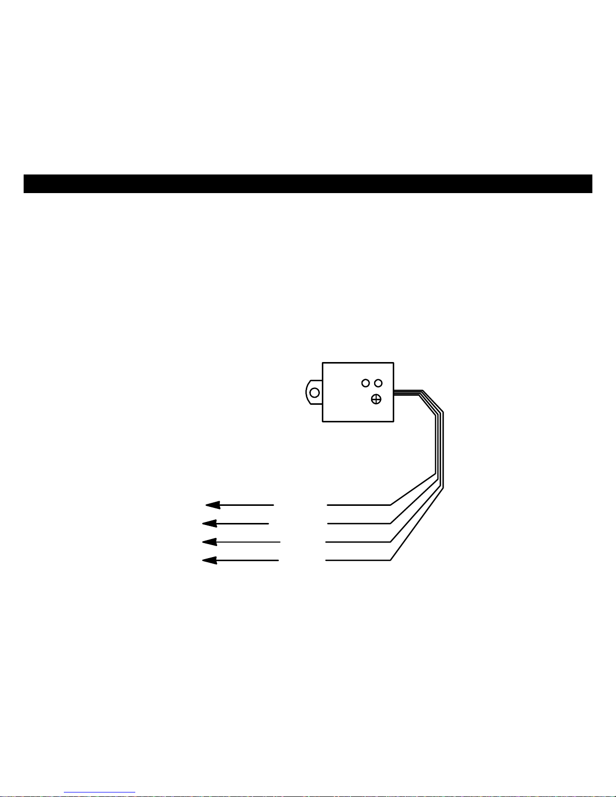
WIRING:4-PINShock Sensor(22 Gaugewires)
SHOCK SENSOR: Thesensorsupplied withthissystemdoesnotrequireanyadditionalwiring.Simplymountthe
sensorinasuitablelocation,plugitin,andadjustthesensitivity.Thereare2LED’sontheshocksensortoassist
youinadjusting sensitivity.The Blue LEDindicatesthe “Warn Away”leveland theRed LEDindicatesafull alarm
shocksensorviolation.
NOTE:Yoursensor mayhave1or 2adjustmentknobs(dependingonmodel)toadjustbothPre-Warn andalarm
trigger.
BLUELED REDLED
(-)PRE-WARN
(-)TRIGGER
GROUND
12VOLTS
YELLOW
ORANGE
BLACK
RED
(Trigger)
(Pre-Warn)
Adjustment
SHOCK SENSOR
12 VOLTS
GROUND

12
CrimestopperDoorLock Accessories:
CS-6600DLM: Dual-relayplug-inmoduleforReverse
Polarity,Positive, orAftermarket Motors.
CS-6500DLI: Plug-inpulseinverterthat convertsthe
Negativeoutputsof the systemtoPositivetypeforPositive
DoorLock systems.
CS-610S1: Aftermarket doorlock actuator(motor).
POWERDOORLOCKS:WIRING&SYSTEMTYPES
PIN1:BLUE: (-)NegativepulseforUNLOCK
PIN2:RED: 12VWhen using externalrelays(TERM86)
PIN3:GREEN: (-)Negativepulsefor LOCK
DETERMININGDOORLOCK TYPE: Werecommend
determiningthe typeoflocking systemthe vehiclehas
beforeconnectinganywires.Incorrectconnection may
resultindamagetothe alarmand/orvehiclelocking system.
Doorlockinformation isprovidedasaguide. Yourvehiclemaybedifferent.
Negative Trigger(-):ManyImports;LatemodelFord&General Motors
Negativetrigger door locksystemssendaNegative(Ground)pulsetoexistingfactoryrelaystolockandunlockthe
vehicledoors.
Positive Trigger(+):ManyGeneral Motors;Chrysler/ Dodge/ Plymouth
Positivetriggerdoor locksystemssend aPositive(12V)pulsetoexisting factoryrelaystolockandunlockthe
vehicledoors.
Reverse Polarity:ManyFord/Lincoln/Mercury/Dodge/Chrysler/Plymouthandearly90’sGMTrucks
ReversePolaritysystemsusenorelays,butinstead the doorlock/unlockmotorsare controlleddirectlyfromthelock
and unlockswitchesinthedoor.The lockand unlockwiresrestatNegativeGroundwhen notinuse.When the
lockor unlockbutton ispressed,one ofthe circuitsis“Lifted”andreplacedwith+12Vcausing alockor unlockto
occur.
SingleWire(Dual Voltage):Latemodel Chrysler/Dodge/PlymouthVehicles, some2000-UPGM
DualVoltagesystemshavelock/unlock switchesthatsend varying levelsofPositivevoltage ORNegativeground
currenttotheSAMEwire forbothlockand unlock.When the vehicle’sBodyComputer Module(BCM) ordoor lock
modulesensesdifferentvoltageson thiswire,the systemwill either lockor unlock.Singlewire door locksystems
requirerelaysandresistors.
DatabusandCanbusSystems(Data ModuleRequired)
Databussystemssend lowcurrent“Datamessages”tothe doorlockcontrollersonanetworkinordertolockand
unlockthevehicle.Toinstall aftermarketsystemsinthesevehicles,aninterfacemoduleisrequiredthatconverts
the regular lock/unlockpulsesinto“Datamessages”toallowlocking &unlocking.Interfacemodulesaresold
separately.

13
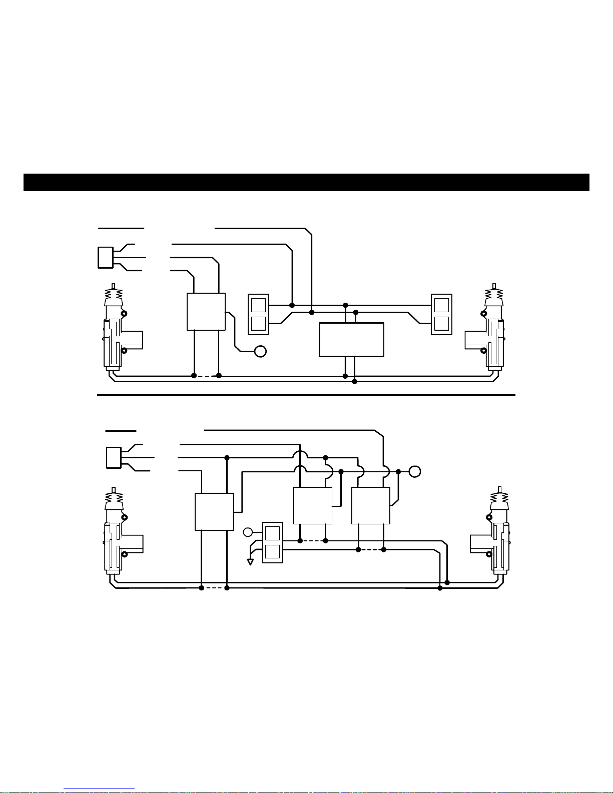
DOORLOCK WIRING
AFTERMARKETMOTOR/DOORLOCKWIRING
REVERSE POLARITYDOORLOCKWIRING
GREEN
GREEN FUSED
FUSED RED
RED +12V
+12V BLUE
BLUE +
+
86858685
8685
8685 8787
8787 3087A3087A
3087A3087A
+L
CUT
UL
CUT
MASTER
SWITCH
NEGATIVETRIGGERDOORLOCKWIRING POSITIVETRIGGERDOORLOCK WIRING
GREEN
GREEN FUSED
RED +12VRED BLUE +
BLUE
86
858685 8787 3087A30
87A
FACTORY
FACTORY
LL
POWER
POWER LOCKING
LOCKING
UL UL
RELAYS RELAYS
14
SEPARATEDRIVER’SDOORUNLOCK WIRING
NEGATIVE TRIGGERDOORLOCKS
BLUE/WHITE
GREEN
RED
BLUE
DRIVER'S
DOORMOTOR
8685 LL
87 ULUL
87A
30 FACTORY LOCK
RELAYS
+12V
+FUSED
UNLOCKWIRE CUT
WIRINGFORREVERSE POLARITYDOORLOCKS
BLUE/WHITE
GREEN FUSED
RED +12V
BLUE +
MASTER
86858685
SWITCH
8685 8787
87 30
87A
30
87A
30 87A
+
L
CUT
UL
CUT
CUT
UNLOCK WIRE
LOCKWIRE

15
TACHLESS MODE
YoursystemincludesaTach-lessmodethat activelymonitorsandcomparesthe vehicle’srestingvoltageversusits
runningvoltageeachtimearemotestartisperformed;[insteadofthe conventionaltach-pulsemethod]. Smart
Tachlessmodeadjustsautomaticallytomaintainoptimumefficiencyoverthelifeoftheinstallation.
IMPORTANTNOTES:
OntherareoccasionthatTachless mode doesnotoperatesatisfactorily,change the voltage referencelevelas
describedbelow, oruseadifferent modesuchas“TachReference”mode,or “Timed Crank”mode.
TACHLESS ADJUSTMENT:
IntheeventTachless over-cranksorunder-cranksyour starter,thesettingscan be changed.The purposeof
adjusting the “SmartTachless”Mode istoraiseor lower thevoltage referencethresholdfromthe 93%defaultpoint.
Raisingor loweringthis93%pointshouldincreaseor decreaseyourcrankingtimerespectively.You canadjustthe
range from79%to100%inone percentincrements.Factorydefaultsetting [starting point] isinthe middleat93%
whichshouldworkfor mostvehicles.Ifyoufeelyou needtofine tune the Tachless mode,thenfollowthesteps
belowtoadjust itsreferencelevel.
1.Openhood(or groundthe Blue hood pinwireifno hood pinisinstalled)
2.Turn the keytotheONposition (donotstartvehicle).
3.Press programbutton5times,after afewsecondsthe unitwill flashthelights5times.
4.Carefullypresstheprogrambutton24 timestogettooption#24.You mustgetalightflashafter eachpress.If
the lightsdidn’t flash, thentheunitdidnotregisteryourbuttonpress. Onlycount thelight flash.
5.Press theLockButton #1on the remotetodecreaseby1%(lightswill flash1Xforeachpress);Pressthe Trunk
Button#3toincreaseby1%(lightswill flash2Xfor eachpress);PresstheUnlockButton #2 toresetto93%
(lightswill flash3X).The unitwill stopprovidinglightflasheswhenyou reachthe bottom(79%)or thetop (100%)
of theadjustmentrange.If youlost track, then justpress Button#3toresetbackto93%andbeginagain.
6.Turn Ignition OFF,Closehood(or un-ground theBluewire) andcheckoperation.
Note:Theminimumstartercranktimeis0.8secondsbydefault.Youcanincreaseordecreasethisby0.1
secondsusingOption#21.Minimum=0.5seconds.

16
TACH MODEPROGRAMMING
INTRODUCTION
Thissystemhas3methodsof monitoring the enginerunning.Option#1controlshowthe systemmonitorsthe
engine running.
1. TachReferenceMode–MonitorsEngineR.P.M. -Most reliablemethod, seeTachprogramming below.
2. TachlessMode-Default. When vehicleisremotestarted,thebatteryvoltage ratewill goupbecausethe
Alternatorstartsworking. TheTachlessMode isadjustablein1%incrementsthruOption21.
3. Not Used.
4. HybridMode– Forelectricmotorsthatarecomputercontrolled. Thisprovidesa4secondcrankoutput to
activatethe start sequenceon Hybridvehicle. Don’tuseon vehicleswithgasordieselengine, doesn’t monitor
stalledengine or lowbatteryvoltage.
TACH REFERENCEMODE: Providesreliableremotestarting performancethough engine speed sensing.When
using TachReferenceMode,the WHITE/REDwireisusedforTachsignal[EngineRPM]input.Mostmodern
enginesincludevariouspointswhere the Engine Speed[Tach]or A/Csignalmaybeobtained.TachSignal
examples:FuelInjection Solenoids,Negative(-) side ofignitioncoil,attheDistributororIgnitionControlModule,
Coil Pack,EngineComputer,orCrankshaftSensor.SometimesanAlternatorStatorpincanbe used.TheseTach
Signallocationsmentionedareprovided asaguide,your vehiclemaydiffer.Somelocationswill NOTbe agood
location forTachsourcedue toRFnoiseorComputerData.
Note:WhenusingaDatabusmoduleforTachsignal, don’tconnectup theTachwire.Thiswill create a
conflict. TheSystemcanonlyuseoneTachsource.
TACH PROGRAMMING:
1.Red WhitewireshouldbeconnectedtoavalidTachsource.
2.Startenginewithkey.
3.Press programbutton5times,then wait for5lightflashesand/or5hornhonks.
4.Pushprogrambuttononcemore. (Youmust getonelight flashand/orhonkafter button ispressed.)Thisunit is
nowat option #1-TachLearning.
5.Press the#1LockButtononremotetransmitter. Theunitwill readthe Tachsourceand flashthelightsandor
honkonceforprogramconfirmation. (Onmodelswithoutremotetransmitters,press the brakepedalinthisstep.)
6.Iflightsdonotflashforconfirmation, then tryanothertachsourceortrythetachfindertolocateanother wire

17
TACH FINDER&USEFUL TIPS
TACH FINDERMODE:
ThisTachFindermodecanassistinlocatingaTachsourcefor yourinstallation.When following thesteps,the unit
will begintoflashtheparking lightsifyou havethe Red/Whitewireconnected toatachsource.If lightsdonotflash,
thentryanother wire until youlocateatachsignalthatwill causethe Parking lightstoflash.NOTE:Onsome
vehiclesequipped withdaytimerunninglights,itmaybedifficulttoseeanyflashing parking lights.Inthiscaseyour
onlynotification will betheslight“ticking” sound coming fromthemodule’sflashing lightrelay.
TACH FINDERSTEPS:
1.Openhood(or groundGrayhoodpinwire ifno hood pinisinstalled)
2.Start Engine withthe key.
3.Press theProgrambuttonfor2seconds
4.Lightswill beginflashing iftheRed/Whitewireisconnectedtoavalidtachsource. If not tryadifferenttachwire.
5.OnceTachislocatedthenturnoffengine andclosehoodtoabort (RemoveGrayhood pinwire fromground).
6.Nowfollowthe TachProgrammingsteps.
TACH FINDERTIP:ColdWeather/ High IdleSimulation:
The tachfinder mode canalsobeusedtohelpdeterminehowyourCoolStartsystemmayoperateinacoldweather
situation.Onceyouhaveavalidtachsourceprogrammed intoyoursystem, followtest stepsbelow.
1.Gointothetachfindermode.
2.Youshouldhaveaconsistent lightflash(likedirectionaloremergencyflashers).
3.SlowlyraisetheRPMlevelonyour vehicletosimulatea“warm-upidle” that ishigher thanthe normalidle
level.If and whenthe lightsSTOPflashing. Meansthat thisisthepointatwhichthetachsignalisoutofrange
of thesystem.
4.Werecommend thatyou bring theRPMleveluptoaround1000RPM’stosimulateacoldmorningidle.
5.Ifthelightsstopflashing, thenwerecommend using another tachsource. Thismayhelpprevent the engine
fromstarting andstallinginthe morningor coldweather.
6.Iflightsflashwithengineoff,you’reconnected toavehicledatawire.

18
DIESEL GLOW PLUGDELAY
Thisfeatureprovidesasolution for dieselvehicleswithouthavingtoconnecttothe GlowPlug-“WaittoStartCircuit”
input.Thismaybe due toavarietyofreasonsforexample:If your vehicledoesnothaveaviable“WaittoStart
Circuit”or youcannotlocateandidentifythecircuit. You canchoosefromaselection of“pre-cranking” delaytimes.
Oncethismode isactivated,thesystemwill NOLONGERmonitorthe PINKglowplug inputwireandwill usea
delaysettingchosenbytheinstaller inthe option chart.
NOTES:ThisfeatureisOFFbydefaultand mustbe programmed before use.Oncethisfeature isturnedON,the
PinkGlowpluginputwire isnotused.The Remotestartunitwill alwayswaitthe programmed timebefore cranking
EVENIFtheglowplugswarmup first.Thereare3differentDelaytimesavailablefor use:10,15,or20seconds.
SEE PROGRAMMING OPTIONCHART, nextsection.
HOWTO USE THISFEATURE:
1.See the “ProgrammableOptions”nextsectionandchangeOption#22from"MonitorGlowPlugLight"toone of
the delayedtimevalues.(Defaultsettingistoalwaysmonitorthe PINKGlowPlug inputwire.)
2.Oncethisoptionhaschangedthe system will wait for the selectedtimebeforecrankingtheengine.
PROGRAMMABLEOPTIONS
You canprogrammultipleoptionsinonesessionifyoustart withthe lowestoption andcontinueontohigheroptions
[ifneeded]withoutrepeating steps#1-3 below.For example,youcanfollowthe programmingstepstochange
Option#2to“OFF”bypressingthelockbuttonontheremote,then youcancontinuepressing theprogrambutton
additionaltimestogettoahighnumberoption and change the settingwithouthavingtorepeatSteps1-5.Youcan
onlygo fromlowtohigheroption numbersinone session.
To EngageOption Programming:
1.Turn KeytotheONpositionand wait5seconds.
2.Press valet/ programbutton5times,after afewsecondstheunitwill chirp/ flashthelights5times.
3.Pushthe valet / programbutton[again]the number of timesthat correspondstotheoptionnumberdesired (1
thru31).Youmustgetachirp/ lightflashaftereachbuttonpress. Seechart onnextpagefor option list.
4.When youreachthe desiredprogramming level, Pressbutton#1,#2 #3 or#4tochange the option(youcan also
pressbrakepedal1-4 times)..Youwill get1-4chirps/ light flashesasconfirmation.
5.Turn Ignition OFFandcheckforchanged features.
19
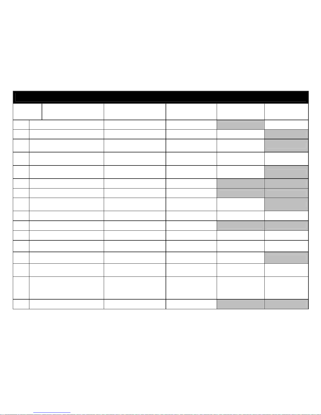
OPTIONPROGRAMMINGTABLE
Option#
OptionDescription TXButton#1 *TXButton #2*
(Default Value) TXButton#3 TXButton#4
1 EngineMonitoring LearnTach *Tachless* HybridMode
2 Pink/WhiteWireSelection (+)ACC 2 (+)*IGN2* (+)START2
3 PassiveArming PassiveArmwithLock *OFF* PassiveArm
without Lock
4 ActiveRe-Arm/ AutoRe-Arm ActiveRe-ArmwithLock *OFF* AutoRe-Armwith
Lock AutoRe-Arm
without Lock
5 Arm / Disarm thruOEM
Remote(datamodeonly) ON *OFF* ONwith3Press
Lock =Start
6 ParkingLightsonw/Disarm OFF *ON*
7 DataPortProtocol ADS-OFASeries *EVO &SLSeries*
8 RemoteStart&TrunkPop
ButtonPress DoubleButton Press *½Second Press* Press and Hold2
seconds
9 3 ChirpswithRemoteStart OFF *Siren* HornHornand Siren
10 Disarm withTrunkPop OFF *ON*
11 OpenDoorWarning 5Sec. *60 Seconds* 15 Seconds30 Seconds
12 DoorLock Pulse Time 3Sec. *0.5Seconds* DoubleUnlock WakeUpPulse
on Unlock
13 AutoLockwithIgnition Lock and Unlock *OFF* SecurityLock with
IGNdoor&Brake
14 Lock withRemoteStart OFF *Lock withRemote
StartOnly* Lock withRemote
Start and Abort Lock withAbort
Only
15 TransmissionType ManualTransmission set
withRemoteControl*Automatic* Manual
Transmission set
withHand Brake
Manual
Transmission with
autoshutdown
afterdoorclosed
16 Unlock beforeRemoteStart ON *OFF*

20
OPTIONPROGRAMMINGTABLE
17 Blue/Black WireFunction AUX#2 Momentary *(-) WhenRunning*
18 SirenOutput TriggerOnly *Arm / Disarm/
Warning / Trigger* Warning &Trigger
19 HornOutput TriggerOnly Warning &Trigger
20 HornChirpConfirmation 1Press 2Press
21 HornPulse (ChirpDuration) 15 milliseconds 20 milliseconds 40 milliseconds
22 MinimumStarterCrankTime (-) 0.1Seconds *0.8Seconds* (+)0.1Seconds (+)0.4Seconds
23 Diesel Glow PlugDelay 10 Seconds *MonitorGlow Plug 15 Seconds 20 Seconds
24 RemoteStartEngineRun
Time 10 Minutes *20 Minutes* 30 Minutes 5Minutes
25 SmartTachlessVoltage
Adjustment79-100%-1% *Setto93%for
default* +1%
26 IdleDownRun Time 10 Minutes *20 Minutes* 30 Minutes InfinityRun
27 Aux#3 SteadyMomentary (-) *ACC* Timed LatchOn/Off
28 Aux#3Time:1to255 sec. -1Second *12 Seconds* +1Second +10 Seconds
29 Aux#4 SteadyMomentary (-) *IGN* Timed LatchOn/Off
30 Aux#4Time:1to255 sec. -1Second *12 Seconds* +1Second +10 Seconds
31 Turbo TimerMode1Minute *OFF* 3Minutes 5Minutes
32 PINK WirefunctionPassiveCarjack *Glow Plug*
33 1-Wayor2-Way 2-Way 1-Way
34 SmartPhonebaudrate 9600 115200
35 ResetOptionstodefault(*) *ResetOptions1thru32*
1. EngineMonitoring:
Thisoptioncontrolshowthe systemmonitorstheenginerunning.Youcanprogramfor Tachless modethatmonitors
batteryvoltage, Tachmodeinwhichtheunit usesaTachsignal(RPM) orfor Timed Crankasanalternative. There
are4choicesfor thisoption:
This manual suits for next models
1
Table of contents
Popular Car Alarm manuals by other brands

Directed Electronics
Directed Electronics 600 ESP owner's guide

Pyle
Pyle PWD202 user guide

CrimeStopper
CrimeStopper CM-2500 user manual

AUTO SHIELD
AUTO SHIELD AS-675 Operation manual

Black Widow
Black Widow BW-1020 NEW AVENGER installation manual

Audiovox
Audiovox Prestige Platinum APS-596N installation manual


ictor
ictor Luxury start VT-368 user manual

Python
Python 875XP owner's guide

Audiovox
Audiovox Prestige Platinum APS-510 installation manual

Hornet
Hornet 742T installation guide

Directed Electronics
Directed Electronics AdvantGuard 5 owner's guide

Freedom
Freedom Freedom 411atv Owner's manual & wiring instructions