Fortress Technologies TR210 User manual

1
TR210 Mini Kiosk User Manual
Model No.:TR210
Disclaimer
This manual is authorized and belongs to (Fortress GB Ltd.), without permission, any unauthorized copying is forbidden.
The content of this manual can’t represent the commitment of Shenzhen Geshem, as the company continues to improve its
products; the company has the right to modify this manual without further notice.
We have no responsibility for any direct/indirect/intentional or unintentional damages and potential problems caused by
unsuitable installation and usage.
Guarantee Clause:
The product has 12months warranty. If the user has a special requirement, please do it as
the contract signed by the two parties.
Safety Instruction
1. Please read the user manual carefully before using the product, and
carefully keep it for future reference.
2. Before connecting the power supply to the product, please confirm the
voltage is compliant with the requirement of the device.
3. To avoid electric shock or damage to the product, please unplug the power
cord from the socket before cleaning the device withthe wet rag.
4. Please do not use liquid or aerosol cleaner to clean up the device.
5. To avoid short circuits or fires, please do not let any liquid get into or splash
into the product.
6. For a device that needs to use a power cord, there must be an easy-to-reach
power socket around the device.
7. Please do not use the product in a damp environment.
8. Before installation, please make sure the device is placed on a solid surface;
accidental drop or tipping may cause malfunction or damage to the device.
9. Before you connect or unplug any signal cable, make sure all power cords
are unplugged in advance.

10. To avoid unnecessary damage caused by frequent power-on/off, wait at
least 30 seconds after turning off the computer before re-turning on the computer.
11. If the product will not be used for a long time, please disconnect the power
cord, to avoid damage to the product by transient voltage.
12. If the product needs to be upgraded, installed or dismantled, please
implement all the operation on an ESD workstation, for some precision devices are
sensitive to ESD;
13. Ensure excellent heat dissipation and ventilation of the system.
14. Please do not open or dismantle the device by yourself. For the sake of
safety, this device can only be opened by a professional maintenance person.

Packing List
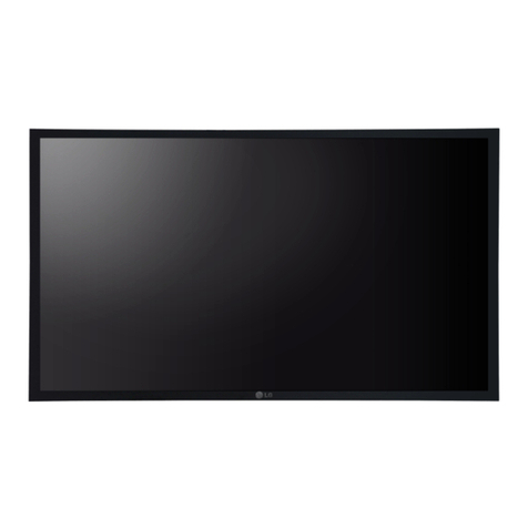
A TR210 Mini TR210 Mini Kioskwith touch screen
1*AC 100V~240V transferred to DC+12V/3A Power adapter
1*AC 110V~240V to DC+12V/3A power adapter
1*AC220V power cable
1*Certification, 1*packing list

Contents
TR210 Mini Kiosk User Manual..................................................................................................................................1
1.Product Introduction ............................................................................................................................................1
1.1 Brief Introduction .....................................................................................................................................................................1
1.2Product specifications..............................................................................................................................................................2
1.3 I/O Interface Introduction........................................................................................................................................................4
2.Application Planning............................................................................................................................................5
2.1 Transportation..........................................................................................................................................................................5
2.2 Storage Requirements............................................................................................................................................................5
2.3Unpack and check the delivered equipment ........................................................................................................................6
3.Installation Instructions .......................................................................................................................................7
3.1 Product photo ..........................................................................................................................................................................7
3.2 Product Image & Dimensions Drawing ................................................................................................................................7
3.3 Installation Sketch ...................................................................................................................................................................8
4.Product Specification ..........................................................................................................................................9
4.1 Basic software Specification ..................................................................................................................................................9
4.2 Functions ..................................................................................................................................................................................9
4.3 Technical Features ..................................................................................................................................................................9
4.4 Interface definition.................................................................................................................................................................10
4.5 Network interface .................................................................................................................................................................. 11
4.6 COM definition (RJ45 output).............................................................................................................................................. 11
4.7 Standard HDMI A Type interface.........................................................................................................................................12
4.8 Power interface......................................................................................................................................................................12
5.FCC Caution.....................................................................................................................................................13
5.1 FCC Caution ..........................................................................................................................................................................13

1
1.Product Introduction
1.1 Brief Introduction
TR210 is a low-power-consumption, high-performance and fan less embedded Box PC, and
its material is ABS plastic. TR210 is working with NFC card only and QR code working in one
single door controller, it used the chipis that is up to industrial grade single chip. With high
stability, large capacity, full function, and reaction fast and simple operation. It is best for used
on company office,factory,house,residential quarters,offices,mechanical and electrical control
equipment and so on.
This product is with Cortex-A17 and the on-board RK3288 SoC Quad Core @ 1.8GHz
processor, 2GB memory and16GB eMMC storage, and it has rich I/O interfaces and it is with
fully-sealed Fan less design, supporting Android 7.0. or above.
This product can be used in the field of mechanical equipment, Solar photovoltaic, Vehicle
controlling and industrial automation (like paper-making, environment protection. etc.).

2
1.2Product specifications
Item
Definition
Mai
n
Ind
ex
Processo
r
RK3288 SoC Cortex-A17 Quad Core @ 1.8GHz Max.
Memory
Standard 2GB DDR3
OS
Google Android7.0 or above
Storage
EMMC 8GB/16GB/32GB select(standard 8GB ),NAND Flash compatible
Network
Function
1*RJ45 1000M LAN
Include BT+WIFI module, support Wi-Fi 802.11a/b//g/n/ac,2.4G/5G dual band,
Support BT 4.0 dual antenna
Support 3G- WCDMA、EVDO、CDMA、GSM, 2G/3G full bands (optional);
MiniPCIe slot;SIMslot for Standard card:25mm*15mm;
850/900/1800/1900MHz/2100MHz (optional)
Support 4G , LTE-TDD/LTE-FDD/TD-SCDMA/EDGE/GPRS/GSM(optional)
Audio
1*Line out
Expansio
n
Support Mini-PCIE (Optional 4G LTE wireless communication.)
LED
display
features
Display: 4.3″TFT LED
Resolution:4.3″---480*272;
Brightness:4.3″---250cd/㎡
Visual Angle(CR≥10)
Horizontal Level:80°~80°;Vertical:80°~80°
Touch
Screen
Connection: USB
Type: Multi-points Capacitive touch
I/O
Provide 4 COM(RJ45 output):COM1(RS232),COM2(RS232),COM3(RS232),
COM4(RS232)COM:4*RS232 (RJ45)
2*USB
1*1000M LAN
1*HDMI
1*audio in/ out
1*TF Card slot
1*SIM card slot
Mai
n
Fu
ncti
on
Dimensio
ns
320mm(L)*170mm(W)*73mm(H);
Mechanic
al
Housing: Metal
Color: Black/White
Heat conduction: Al-alloy body with heat conduction design
Material: high-density al-alloy cooling panel

3
Item
Definition
Weight
TR210: N/W:1.9Kg;G/W:2.55Kg
TEMP
Operation temperature:-10℃~50℃with air flow
Storage temperature:-20℃~60℃
Humidity
95%@40℃( non-condensing)
EMC
Meet GB9254 Level A
Meet GB/T 17618
RELIABILIT
Y
MTBF≥5000h
MTTR≤0.5h
Safety
Meet basic requirement of GB4943
Protectio
n Level
Front Panel IP65(Optional)
ENVIRONM
ENT
Anti-vibration:5-19Hz/1.0mmamplitude;19-200Hz/1.0g acceleration
Anti-Shock:Acceleration 10g,11ms duration;
Power
feature
Input Volt/Freq:100~240VAC/50~60Hz(Adapter);
Input Volt/Current:12V DC(Optional without adapter);
Power 7.2W(standby),13.2W(rated)
Hardware
Version
N/A
Software
Version
N/A

4
1.3 I/O Interface Introduction
DC Port
HDMI
USB 2.0
USB 2.0
SIM Slot
5V-GND-12V-12V-GND-PE/IN
TF port
Line Out
POE port
CTRL1 -COM1-COM2-CTRL2-COM3-COM4

5
2.Application Planning
2.1 Transportation
Well-packaged products are suited for transportation by truck, ship, and plane. During transportation,
products should not be put in open cabin or carriage. During transshipping, products should not be
stored in open air without protection from the atmospheric conditions. Products should not be
transported together with inflammable, explosive and corrosive substances and are not allowed to be
exposed to rain, snow and liquid substances and mechanical force.
2.2 Storage Requirements
Products should be stored in package box when it is not used. And warehouse temperature should be
0OC~40 OC, and relative humidity should be 20% ~ 85%. In the warehouse, there should be no harmful
gas, inflammable, explosive products, and corrosive chemical products, and strong mechanical
vibration, shock, and strong magnetic field interference. The package box should be at least 10cm
above ground, and 50cm away from wall, thermal source, window, and air inlet
Caution!
Risk of destroying the device!
When shipping the PC in cold weather, please pay attention to the extreme temperature variation.
Under this circumstance, please make sure no water drop (condensation) is formed on the surface
or interior of the device. If condensation is formed on the device, please wait forover twelve hours
before connecting the device.

6
2.3Unpack and check the delivered equipment
Unpack the equipment
Pay attention to the following things when you unpack the equipment.
Please take the advice not to throw away the original packaging material and please retain to use it when
the equipment should be transported again.
Please put the document in a safe place. It will be used in the initial adjustment of equipment and it is a
part of the equipment.
When you check the delivered equipment, please check whether it is obviously damaged during the
transportation.
Please check whether the delivered parcel includes the whole equipment and the accessories you ordered
separately. If there is any discrepancy or damaged during transportation, please contact our
customer-service staff

7
3.Installation Instructions
3.1 Product photo
Photo 3-1
3.2 Product Image & Dimensions Drawing
photo 3-2

8
3.3 Installation Sketch
1.Casing
2.Front Plate
3.Back Plate
4. Cover
5. LCD frame
6.installation stand
7.Speaker
8. POE Stand
9.Screen
pressure plate
10. Rear baffle
assembly

9
4.Product Specification
4.1 Basic software Specification
OS
Google Android 7.0 and above
Basic software
function
web browser, Online chat, e-mail,E-book,Resource manager
Sound Mode
Calendar, Clock, Calculator, recording
Language
support
Multiple language
Recording
Support MP3, WMA format
TOOL
Calendar/Alarm Clock/calculator/notes/weather+ clock/recording
Word
processing
EPUB, WORD, EXCEL, POWERPOINT, PDF, TXT
E-book
PDF/TXT/CHM/DOC/EXCEL/EPUB/RTF/FB2
Input method
Standard Android key-board, Optional third-input (optional Chinese,
Korean, Japanese etc.)
Net
Browser –Chrome Lite/GOOGLE Market/Email/Gmail/Google talk
System
management
APK installer, Original Android system, open root authority, support ODM
development /System setting/google Maps/global time/support OTA
remote-upgrade
4.2 Functions
1.Storge 5000 card (ID/IC optional)
2.Can be continuous-read and enroll card, and automatically default the
number and card password.
3.With these 2 functions: swipe card for open the door or swipe card for
closed the door.
4. The signal for open the door is output by relay control directly (NO/NC
optional)
4.3 Technical Features
NO
Item
Specification

10
1
Power supply
DC: Voltage 12±10%;
current<1.3A
2
Max Output
Electro lock output:2A
3
Ambient temp
-10℃~70℃
4
RH
20%~90%
5
Capacity
5000 usercards
6
Reading Distance
0-5cm
7
Cardtype
ProximityorMifare Card
4.4 Interface definition
1.This device provides 2*USB 2.0, and definition as below:
USB1~2
USB2.0
Signal
1
5V
2
D-
3
D+
4
GND

11
4.5 Network interface
1*1000M LAN interface, definition as below
LAN
ACTLED
(Single Green
Light)
Network status
LILED
(Double:
Green/Orange)
Network Speed
Green
1000Mbps
Twinkle
data
transmission
Orange
100Mbps
Light Off
No data
transmission
Light Off
10Mbps
4.6 COM definition (RJ45 output)
This device provides 4*RS232 Definition as below
COM1~4
PIN
Signal
RS-232
1
NC
2
NC
3
GND
4
RXD
5
GND
6
5V
7
TXD
8
5V

12
4.7 Standard HDMI A Type interface
HDMI
PIN
Signal
PIN
Signal
1
DATA2+
2
DATA2shielding
3
DATA2-
4
DATA1+
5
DATA1 shielding
6
DATA1-
7
DATA0+
8
DATA0shielding
9
DATA0-
10
DATA1_CK+
11
DATA1_CKshielding
12
DATA1_CK-
13
CEC
14
Reserved
15
SCL(DDC clock)
16
SDA(DDC data)
17
DCC/CEC GND
18
+5V
19
Hot swap check
/
4.8 Power interface
This device support DC +12V power input, can with power adapter,
definition as below
DC12V input
PIN
Signal
1
+12V
2
GND

13
5.FCC Caution
5.1 FCC Caution
Use distance:>20cm (Use distance means the distance between the product and user).
This device complies with part 15 of the FCC Rules. Operation is subject to the following two
conditions: (1) this device may not cause harmful interference, and (2) this device must accept any
interference received, including interference that may cause undesired operation.
Any changes or modifications not expressly approved by the party responsible for compliance
could void the user's authority to operate the equipment.
NOTE: This equipment has been tested and found to comply with the limits for a Class B digital
device, pursuant to Part 15 of the FCC Rules. These limits are designed to provide reasonable
protection against harmful interference in a residential installation. This equipment generates, uses
and can radiate radio frequency energy and, if not installed and used in accordance with the
instructions, may cause harmful interference to radio communications. However, there is no
guarantee that interference will not occur in a particular installation.
If this equipment does cause harmful interference to radio or television reception,
which can be determined by turning the equipment off and on, the user is encouraged to try to correct
the interference by one or more of the following measures:
-- Reorient or relocate the receiving antenna.
-- Increase the separation between the equipment and receiver.
-- Connect the equipment into an outlet on a circuit different
from that to which the receiver is connected.
-- Consult the dealer or an experienced radio/TV technician for help.
RF EXPOSURE STATEMENT
This equipment complies with FCC radiation exposure limits set forth for an uncontrolled
environment. It should be installed and operated with a minimum distance of 20cm between the
radiator and any part of your body.
FCC ID: 2A32E-TR210
Table of contents

