Fosgate Audionics FAP T1 User manual

FAP T1
HOME THEATER AUDIO
7.1 CHANNEL PREAMP/PROCESSOR

Introduction
2
Thank you and congratulations on your purchase of the Fosgate Audionics Preamp/Processor. The FAP T1 combines the best
technologies, components, and software with a clean, user-friendly style, impeccable audio performance and leading edge
capabilities, making it the perfect foundation for any music or home theater system.
This manual contains information on using the FAP T1 Preamp/Processor. It is organized into two sections. “Installation”
covers the location and connection of the preamp/processor in the system. Like many precision components, careful
attention to the initial setup can yield dividends in higher performance and trouble-free use. “Operation” covers the
controls and features of the preamp/processor, and how to use them to get the best effect. We strongly urge reading over
the Installation and Operation portions of this manual before putting the FAP T1 into service.
IMPORTANT: The FAP T1 is shipped from the factory in the following default mode:
Output Configuration 7.1
Speaker Size Small
All Crossovers 100Hz
After reading the rest of this manual and determining how your system should be set up, please refer to pages 18-24 to
change these settings.
If your system will be operated in less than a 7.1 channel configuration, some DSP modes will not be available to you.
Fosgate Audionics .... a talented staff of experienced industry professionals.
Jim Fosgate, Senior Executive Consultant, one of the most renown surround processing circuit designers in the world, holds
more than 25 patents in the audio industry. His latest efforts include Dolby®Pro Logic II—acclaimed as a milestone in matrix
surround technology—and the FAVP1 tube surround processor/preamp. Jim continues to refine his designs in his home audio
laboratories in Utah and Arizona.
Jim Strickland, Vice President of Engineering, has designed some extraordinary products including the famous and highly
regarded Acoustat electrostatic loudspeakers, the trans•nova®power amplifier series and now the Fosgate Audionics
trans•ana 1000.5 amplifier design. He has been a published AES member since 1970 and holds nine audio patents.
Charles Wood, Executive Consultant, originally founded Audionics of Oregon in 1969. In 1986 Audionics merged with
Fosgate Research to form Fosgate Audionics. Charles Wood and Jim Fosgate have been responsible for many industry
"firsts" in multi-channel sound that have been widely adopted throughout the home theater industry.
Gary Church, Chief Acoustic Engineer, has been designing and developing loudspeakers for more than 25 years. His
extensive experience and attention to detail has enabled him to lead a talented engineering team at our Rockford Acoustic
Design (RAD) facility in Michigan.
The Best of All Worlds
Fosgate Audionics, part of Rockford Corporation, is one of the few companies with the resources to design and
manufacture electronic components and loudspeakers to exacting world-class standards.
Fosgate Audionics customer support is second to none—a result of years of experience in designing, building and marketing
sophisticated multi-channel audio products. We know home theater and multi-channel sound inside and out.
Record your FAP T1's serial number and date of purchase here. The serial number is located on the back panel.
Serial Number:
Date of Purchase:

INTRODUCTION ................................................2
SAFETY ............................................................4-5
CONTENTS OF CARTON ....................................6
Unpacking ......................................................6
Contents ..........................................................6
FEATURES ......................................................6-11
Surround Format Information ..........................6
Front Panel ......................................................8
Remote Control ..............................................9
Rear Panel ....................................................10
INSTALLATION CONSIDERATIONS ..................12
INSTALLATION..............................................12-17
Connecting Audio Components ....................13
Connecting Video Components ....................14
FM Antenna ..................................................16
AM Antenna ..................................................16
Connecting an External Amplifier ..................16
Power Connection ........................................16
SYSTEM SETUP ..............................................18-24
Turning ON the Unit ....................................18
Navigating the Setup Menus..........................18
Input Configuration ......................................18
Speaker Configuration ..................................19
Channel Calibration ......................................22
System Configuration ....................................22
Multi–Zone....................................................24
Direct Operation ..........................................24
OPERATION ..................................................25-34
Power ............................................................25
Selecting a Source ........................................25
OPERATION (cont.) ......................................25-34
Volume Control ............................................25
Muting the Volume (Remote Control Only) ..25
Changing the Surround Mode........................26
Surround Data Format Lock ..........................26
Bypass Setting................................................26
Tuner Operation ............................................26
Night Mode ..................................................27
Channel Trim ................................................28
Theater Compensation ..................................28
Multichannel Source Playback ......................29
Analog Bass Management..............................29
Setting the FAP T1 Display Brightness............29
Setting the OSD Time Out ............................29
Sleep Timer ..................................................30
Multi–Zone Operation ..................................30
Remote Control Setup and Operation............31
Battery Installation ........................................31
Setup Using Preprogrammed Codes ..............31
Using the Remote Control ............................32
Macro Buttons ..............................................33
Learning Commands from Another Remote ..33
CARE & MAINTENANCE ....................................35
Cleaning ........................................................35
When You Are Away ....................................35
Troubleshooting ............................................35
System Reset..................................................35
SETUP CODES ..............................................36-37
SPECIFICATIONS ................................................38
CONNECTION RECORD CHART ......................39
INDEX............................................................40-41
SERVICE POLICY & LIMITED WARRANTY ........43
Table of Contents
3

Safety
4
•Read All Instructions –All the safety and operating
instructions of your Fosgate Audionics equipment should be
read before power is applied to the equipment.
•Retain Owner's Manual –These safety and operating
instructions should be retained for future reference.
•Heed Warnings –All warnings on the unit and in the
operating instructions should be adhered to,
•Follow Instructions –All operating and use instructions
should be followed.
•Cleaning –Unplug the unit from the wall outlet before
cleaning. The unit should be cleaned only as recommended
by the manufacturer.
•Attachments –Do not use attachments not recommended by
the unit manufacturer as they may cause hazards.
•Water and Moisture –Do not use the unit near water-for
example, near a bath tub, wash bowl, kitchen sink, or
laundry tub; in a wet basement; or near a swimming pool.
•Accessories –Do not place the unit on an unstable cart,
stand, tripod, bracket, or table. The unit may fall, causing
serious injury to a child or adult, and serious damage to
the unit. Any mounting of the unit should follow the
manufacturer's instructions, and should use a mounting
accessory recommended by the manufacturer.
•Ventilation –Slots and openings in the cabinet are provided
for ventilation and to ensure reliable operation of the unit and
to protect it from overheating, and these openings must not
be blocked or covered. The openings should never be
blocked by placing the unit on a bed, sofa, rug, or other
similar surface. The unit should not be placed in a built-in
installation such as a bookcase or rack unless proper
ventilation is provided. There should be free space of at least
6 inches (16cm) and an opening behind the unit,
•Grounding or Polarization –The unit may be equipped with
a polarized alternating current line plug (a plug having one
blade wider than the other). This plug will fit into the power
outlet only one way. This is a safety feature. If you cannot
insert the plug fully into the outlet, try reversing the plug. If
the plug should still fail to fit, contact a licensed electrician to
replace your obsolete outlet. Do not defeat the safety purpose
of the polarized plug.
•Power Sources –The unit should be operated only from the
type of power source indicated on the marking label. If you
are not sure of the type of power supplied to your home,
consult your unit dealer or local power company.
•Power-Cord Protection –Power-supply cords should be
routed so that they are unlikely to be walked on or pinched
by items placed upon or against them, paying particular
attention to cords where they enter a plug, or a convenience
receptacle, and the point where they exit from the unit.
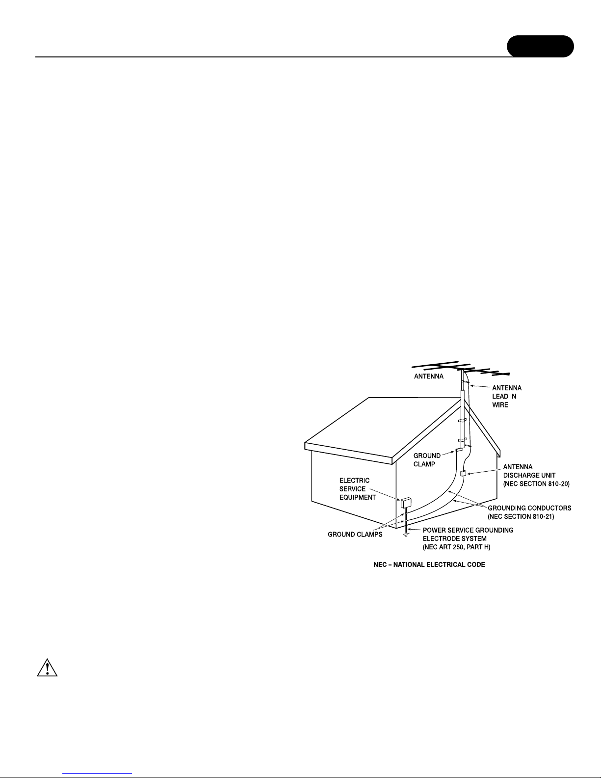
•Outdoor Antenna Grounding –If an outside antenna or
cable system is connected to the unit, be sure the antenna or
cable system is grounded so as to provide some protection
against voltage surges and built-up static charges. Article 810
of the National Electrical Code, ANSI/NFPA 70, provides
information regarding proper grounding of the mast and
supporting structure, grounding of the lead-in wire to an
antenna-discharge unit, size of grounding conductors,
location of antenna-discharge unit, connection to grounding
electrodes, and requirements for the grounding electrode,
•Lightning –For added protection for the unit during a
lightning storm, or when it is left unattended and unused for
long periods of time, unplug it from the wall outlet and
disconnect the antenna or cable system. This will prevent
damage to the unit due to lightning and power-line surges.
•Power Lines –An outside antenna system should not be
located in the vicinity of overhead power lines or other
electric light or power circuits, or where it can fall into such
power lines or circuits. When installing an outside antenna
system, take extreme care to keep from touching such power
lines or circuits as contact with them might be fatal.
•Overloading –Do not overload wall outlets, extension cords,
or integral convenience receptacles as this can result in a risk
of fire or electric shock.
•Object and Liquid Entry –Never push objects of any kind
into the unit through openings as they may touch dangerous
voltage points or short-out parts that could result in a fire or
electric shock. Never spill liquid of any kind on the unit.
•Servicing –Do not attempt to service the unit yourself as
opening or removing covers may expose you to dangerous
voltage or other hazards. Refer all servicing to qualified
service personnel.
•Damage Requiring Service –Unplug the unit from the wall
outlet and refer servicing to qualified service personnel under
the following conditions:
When the power-supply cord or plug is damaged,
If liquid has been spilled, or objects have fallen into the unit,
If the unit has been exposed to rain or water,
If the unit does not operate normally by following the operating
instructions. Adjust only those controls that are covered by the
operating instructions as an improper adjustment of other
controls may result in damage and will often require extensive
work by a qualified technician to restore the unit to its normal
operation,
If the unit has been dropped or damaged in any way, and
great care should be exercised in handling, and the unit
should be examined by qualified service personnel.
When the unit exhibits a distinct change in performance-this
indicates a need for service.
•Replacement Parts –When replacement parts are required,
be sure the service technician has used replacement
parts specified by the manufacturer or have the same
characteristics as the original part. Unauthorized substitutions
may result in fire, electric shock, or other hazards.
•Safety Check –Upon completion of any service or repairs to
the unit, ask the service technician to perform safety checks
to determine that the unit is in proper operation condition.
CAUTION: To reduce the risk of electric shock, do not remove the
cover. No user service-able parts inside. Refer to qualified personnel.
WARNING: To reduce the risk of fire or electric shock, do not expose
this appliance to rain or moisture.
The lightning flash with arrowhead symbol within an
equilateral triangle is intended to alert the user to the
presence of uninsulated “dangerous voltage”within the
product’s enclosure, that may be of sufficient magnitude to
constitute a risk of electric shock to persons.
The exclamation point within an equilateral triangle is
intended to alert the user of the presence of important
operating and maintenance (servicing) instructions in the
literature accompanying the appliance.
NOTICE –IMPORTANT SAFETY INFORMATION –PLEASE READ FIRST
Safety
5
•Wall or Ceiling Mounting –The unit should be mounted to a
wall or ceiling only as recommended by the manufacturer.
•Heat –The unit should be situated away from heat sources
such as radiators, heat registers, stoves, or other units
(including amplifiers) that produce heat.
IMPORTANT SAFETY NOTE
Before connecting a new component such as the FAP T1 to your
audio or home theater system it is always good practice to make
certain that all components arc turned off, and preferably
unplugged from their AC power source. Many modern electronics
products feature automatic turn-on circuits that may be activated
during an installation, causing the potential for damage to
electronic components and/or speakers. Such damage is not
covered by product warranties and Fosgate Audionics specifically
disclaims responsibility for any such damage.
Power Cord
The removable power cord that is shipped with the FAP T1 is
specifically designed to be used with this product. DO NOT use
any other power cord, as that may reduce the unit's, performance
and possibly create a safety hazard. In particular, DO NOT use
standard IEC type power cords designed for computers and other
business equipment products, as they have a three prong plug that
is not meant for use with the FAP T1. Should the power cord
require replacement, use an identical type, or contact Fosgate
Audionics for service.
AC Fuse
The fuse is located inside the chassis and is not user-service-able. If
power does not come on, contact your authorized service station.
Wiring
Cables that run inside of walls should have the appropriate
markings to indicate compliance with, and listing by the UL, CSA
or other standards required by the UL, CSA, NEC or your local
building code. Questions about cables inside of walls should be
referred to a qualified custom installer, or a licensed electrician or
low-voltage contractor.
Do Not Open The Cabinet
There are no user serviceable components inside this product.
Opening the cabinet may present a shock hazard, and any
modification to the product will void your guarantee. If water or any
metal object, such as a paper clip, coin or a staple, accidentally falls
inside the unit, disconnect it from the AC power source immediately,
and contact Fosgate Audionics for further instructions.
Recording Copyright
Recording of copyrighted material for other than personal use is
illegal without permission of the copyright holder.
Note to CATV system installer:
This reminder is provided to call the CATV system installer's
attention to Article 820-40 of the NEC, ANSI/NFPA 70, which
provides guidelines for proper grounding and, in particular, specifies
that the cable ground shall be connected to the grounding system of
the building, as close to the point of cable entry as practical.
FCC Information for User
CAUTION: ANY changes or modifications not expressly
approved by the party responsible for
compliance could void the user's authority
to operate the equipment.
NOTE: This equipment has been tested and found to comply with the limits
for a Class B digital device, pursuant to Part 15 of the FCC Rules.
These limits are designed to provide reasonable protection against
harmful interference in a residential installation.
Tills equipment generates, uses and can radiate radio frequency
energy and, if not installed and used in accordance with the
instructions, may cause harmful interference to radio
communications. However, there is no guarantee that
interference will not occur in a particular installation.
If this equipment does cause harmful interference to radio or
television reception, which can be determined by turning the
equipment off and on, the user is encouraged to try to correct the
interference by one or more of the following measures:
Reorient or relocate the receiving antenna.
Increase the separation between the equipment and receiver.
Connect the equipment into an outlet on a circuit different from
that to which the receiver is connected.
Outdoor Antenna Installation
Safe Antenna and Cable Connection
If an outside antenna or cable system is connected to the equipment,
be sure the antenna or cable system is grounded so as to provide
some protection against built up static charges and voltage surges,
Section 810 of the national Electrical Code, ANSI/NFPA 70 (in
Canada, part 1 of the Canadian Electrical Code) provides information
with respect to proper grounding of the mast and supporting structure,
grounding of the lead-in wire to an antenna discharge unit, size of
grounding conductors, location of antenna discharge unit, connection
to grounding electrodes and requirements for the grounding electrode.
Keep Antenna Clear of High Voltage Power Lines or
Circuits
An outside antenna system should be located well away from
power lines, electric light or power circuits and where it will never
come into contact with these power sources if it should happen to
fall. When installing an outside antenna, extreme care should be
taken to avoid touching power lines, circuits or other power
sources as this could be fatal. Because of the hazards involved,
antenna installation should be left to a professional.

Features
Contents of Carton
6
Your new FAP T1 Preamp/Processor is a state of the art, high
performance audio device. The FAP T1 provides maximum system
connection flexibility with the latest surround processing technologies
assuring compatibility with the widest range of source material.
•6 Digital Inputs (2 coaxial, 4 optical) –Each input is assignable,
providing comprehensive connectivity.
•2 Digital Outputs (1 coaxial, 1 optical) –For use with digital recorders
or distribution systems.
•High Bandwidth Professional Quality Component Video Switching –
HDTV compatible component switching for use with digital set top
boxes and progressive scan DVD players.
•5 Composite and S-Video Inputs –High-quality video circuitry for
connection to your video sources.
•9 Analog Audio Inputs with Bypass Capability –All analog audio
inputs may be switched to Bypass mode for pure analog sound, or
used with the latest surround processing algorithms.
•Video Output Conversion –Video inputs are automatically converted
from composite to S-Video or vice versa when using these outputs.
NOTE:When possible, always transmit video in it's native
connection format.
•High performance AM/FM/FM Stereo tuner with 32 presets
•Audiophile quality preamplifier stages –Provide maximum
performance for critical audio listening.
•Dolby Digital®and Dolby Digital EX®Decoding* –Dolby Digital
decoding delivers 5.1 discrete channels from DVD, satellite, cable
and HDTV sources, while the latest Dolby Digital EX process adds
additional rear surround information for the ultimate home theater
experience.
•Dolby Pro Logic®II* –The latest surround technology from Dolby
Laboratory, designed by Jim Fosgate, delivers 5.1 channel sound fields
from matrix-encoded or stereo recordings.
•DTS®, DTS-ES®and NEO:6 Decoding** –The full suite of DTS
decoding and processing is available to provide multichannel
reproduction from virtually any analog source as well as DTS encoded
programs.
•Cirrus Extra Surround®–The FAP T1 is among the first to offer Cirrus
Extra Surround to provide realistic 6.1 or 7.1 surround sound from
digital and analog sources.
•5.1 Multichannel analog inputs –Connect 5.1-channel outputs from a
DVD-A or SACD multi-channel player or other multi-channel audio
formats to these inputs.
Unpacking
The carton and packing materials used for your new
Preamp/Processor were specially designed to cushion it from the
shocks and vibration of shipping. Save the carton and packing
materials to use if you move, or if the unit ever needs to be shipped
back to us for any reason.
The FAP T1 is heavy and has many front mounted controls and
rear panel connectors, take care when lifting it so as not to cause
damage.
Contents
After unpacking the FAP T1, please check that the following
accessories are in the box:
•Remote Control with Four (4) AAA Batteries
•AC Power Cord
•FM Antenna
•AM Loop Antenna
•Owner's Manual
If for any reason any of the above is missing from your shipment,
please contact Fosgate Audionics immediately.
•Complete Multi-room System –When properly connected, a second
source may be sent to a remote room, complete with remote volume
control, source selection and tuner control. A trigger for the second
zone allows a second amplifier to turn on and off independently of the
main room. This system may also be used to record an input source
that is different from the one being used in the main room.
•2 low voltage triggers –One trigger provides automatic turn on/off of
compatible power amplifiers such as the Fosgate Audionics FAA
1000.5 amplifier or relay-controlled products such as projection
screens, blinds and lighting systems. A separate trigger provides turn
on/off control for an amplifier used with the multi-room system.
* Manufactured under license from Dolby Laboratories.
** Manufactured under license from Digital Theater Systems, Inc. US Pat. No. ,4 1,942
and other world-wide patents issues and pending.
"Dolby," "Pro Logic" and the double-D symbol are trademarks of Dolby Laboratories.
© 1992-1997 Dolby Laboratories, Inc. All rights reserved.
"DTS" and "DTS Digital Surround" are trademarks of Digital Theater Systems, Inc.
© 1996 Digital Theater Systems, Inc. All rights reserved.
"Extra Surround" is a trademark of Cirrus Logic Inc.
SURROUND FORMAT INFORMATION
The FAP T1 employs the latest technology developed in conjunction
with Cirrus Logic®, providing one of the most extensive arrays of
surround decoding and processing currently available. You can
choose from Dolby Pro Logic®II, Dolby Digital®5.1,Dolby Digital
EX®, DTS®, DTS-ES®Discrete, DTS-ES®Matrix, DTS NEO:6®and
Cirrus Extra Surround®. Within each mode, the FAP T1 also offers a
wide range of additional processing options. This means you can
precisely match a surround mode to your program material,
loudspeaker setup and personal taste. In addition, the FAP T1 uses
Cirrus Logic's Triple Crossover®and Precision Bass Management®
features to provide maximum flexibility when setting up your audio
surround system (see "System Setup" on page 20 for further details).
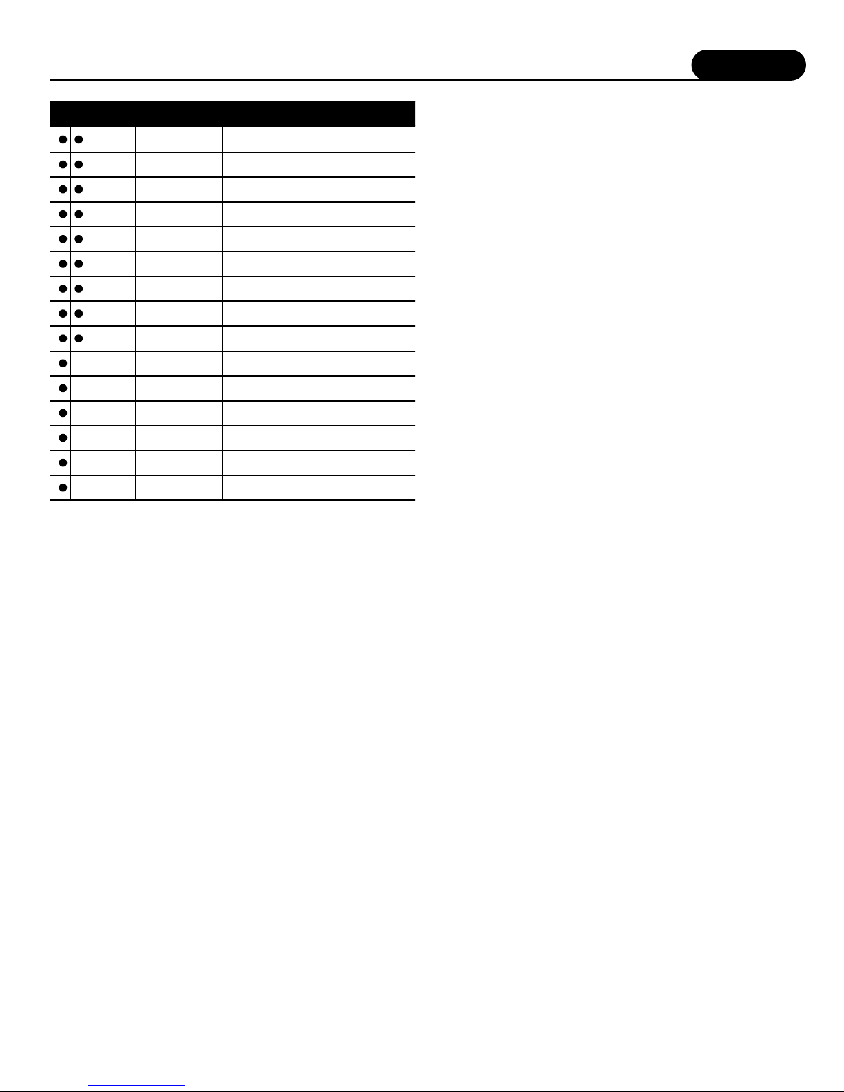
The table on the following page lists the surround processing
choices available within each mode. Depending on the selected
source (D-digital or A-analog) and your loud-speaker configuration,
certain processing options may not appear or operate.
Dolby Digital
This digital audio format provides 5.1 -channel surround sound.
Dolby Digital source material includes DVDs, Laser Discs, HDTV
broadcasts, some satellite delivered programming, and the output
of some digital cable set top boxes.
Features
7
Dolby Digital Surround EX
Film soundtracks encoded with Dolby Digital Surround EX
technology contain an extra channel, added to the soundtrack
during mixing, called Surround Back, which places audio behind
the listener in addition to the existing front left, front center, front
right, surround left, sur-round right, and subwoofer channels. This
additional channel provides more detailed imaging behind the
listener creating more depth, spacious ambience and sound
localization than before.
A list of movies created using Dolby Digital Surround EX can be
found on the Dolby web site at www.dolby.com
NOTE:Surround EX mode can also be engaged during the playback
of 5.1 channel material that is not Dolby Digital Surround
EX or DTS-ES Matrix or Discrete encoded. When used this
way, signals from the left and right surrounds are used to
synthesize the surround back channel. Results using this
method will vary depending on the source material.
Dolby Pro Logic II
Dolby Pro Logic II, designed by Jim Fosgate, is a major enhancement
to surround sound systems. In addition to the full range surrounds,
Pro Logic II allows optimum playback of cinema and music
soundtracks. There are three user adjustable options (found in the
menu) that may be adjusted in Pro Logic II Music mode. In addition,
when the Cirrus Extra Surround processing option is engaged for a
7.1 channel playback, these options remain engaged.
Panorama extends the front stereo image to the surround channels.
It is particularly useful when the source material has a narrow
stereo mix.
Dimension allows the front sound-stage to be more coherently
matched with the surround sound-field, particularly to compensate
for differences between the front and surround speakers, and
speaker location. Personal preference becomes the deciding factor
as to how much Dimension to “dial in”.
Center Width allows blending of center front channel information
into the front left and right channels. This is particularly useful to
compensate when the center speaker is a different type or design
from that of the left and right speakers. When Center Width is used
to the fullest extent, a phantom center is created.
NOTE:In the Pro Logic II Music Mode time delay is disengaged.
Additionally, Panorama, Dimension and Center Width are
not available in the Pro Logic II Cinema mode. Because the
steering logic dynamics of Pro Logic II Cinema and Music
are identical, many listeners often use the Music mode for
both music and cinema playback.
DTS
This compressed digital data format is similar to Dolby Digital, but
uses a higher data rate. DTS also provides a maximum of 5.1 channel
surround channels and is available on compact disc, DVD and Laser
Discs. Audio-only DTS discs may be used with any CD, LD or DVD
player with a digital audio output, but DVD discs with DTS audio
must be used on players with the "DTS Digital Out" logo.
DTS-ES
DTS-ES is an extension of the original DTS format that adds an
additional sixth, or center surround, channel to a soundtrack.
DTS-ES Matrix titles provide the sixth channel by a matrix process,
while DTS-ES Discrete media deliver a true discrete center
surround channel. Both DTS-ES formats are backwards compatible
with the original DTS process, and will deliver a 5.1 channel
output when no center or back surround speakers are available.
The FAP T1 will automatically sense the availability of either
DTS-ES format and automatically switch the processing mode when
required.
DTS NEO:6
This processing mode can create up to 6 full bandwidth channels
from any matrix-encoded 2-channel source. Additionally, this mode
can produce the rear surround information from a 5.1 source.
In Music Mode it can expand stereo music material, such as from a
CD, into a multichannel surround experience.
Cirrus Extra Surround
This unique decoding algorithm creates 6.1 or 7.1 output from
either matrix-encoded or discrete audio signals. When Cirrus Extra
Surround is selected using either the remote or the front panel
controls the display will show the primary selected mode plus a
CR identifier-such as PL2C-CR. To determine what mode is best for
any specific program material it will be necessary to experiment to
decide what suits your systems and personal taste best.
Stereo
This mode provides conventional 2 channel signals to the left and
right front speakers only.
Additional Information
More detailed information about the various surround processing
options contained in the FAP T1 can be found on the following
websites:
www.dolby.com
www.dtsonline.com
www.cirrus.com
D A Name Description
Display
Text
Use for surround enhanced film soundtrack
playback from any 2-Channel source such as VCR
Pro Logic II Cinema
PLII-C
For surround enhanced playback of 2-Channel
(stereo) music
Pro Logic II Music
PLII-M
Equivilant to original Pro Logic surround
processing with mono surround
Pro Logic Emulation
DOLBY PL
Adds Cirrus Extra Surround processing of rear
channels to Pro Logic II Cinema
Pro Logic II Cinema
with Cirrus EX Surr
PLIIC CR
Adds Cirrus Extra Surround processing of rear
channels to Pro Logic II Music
Pro Logic II Music
with Cirrus EX Surr
PLIIM CR
Creates 6.1 channel surround from any
movie-based source
DTS NEO:6 Cinema
NEO: 6C
Creates 6.1 channel surround from any
music-based source
DTS NEO:6 Music
NEO: 6M
Creates a 5-Channel program (L/C/R/LS/RS)
from any stereo source
5-Channel Stereo
5 STEREO
Creates a 7-Channel program (L/C/R/LS/RS/
LSB/LSR) from any stereo source
7-Channel Stereo
7 STEREO
5.1 channel processing for all Dolby Digital
encoded sources
Dolby Digital
DOLBY D
6.1 channel processing for soundtrack
encoded with Dolby EX
Dolby Digital
Surround EX
DOLBY EX
Adds Cirrus Extra Surround post processing to
Dolby Digital. Creates a rear surround channel
Dolby Digital with
Cirrus EX Surr Cinema
DD CR-C
Adds Cirrus Extra Surround post processing to
Dolby Digital. Creates a rear surround channel
Dolby Digital with
Cirrus EX Surr Music
DD CR-M
5.1 channel processing for all DTS
encoded sources
DTS
DTS
5.1 channel processing for all sources encoded
with DTS-ES
DTS Extended
Surround
DTS-ES
Features
8
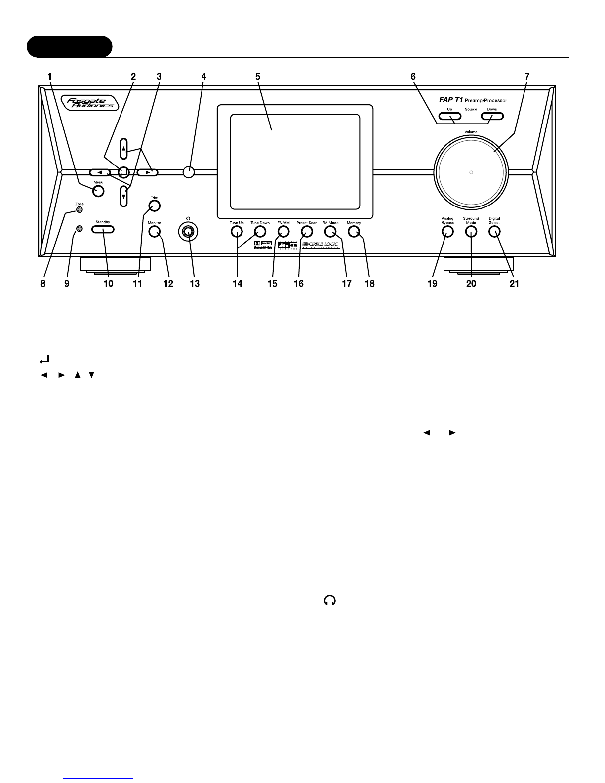
FRONT PANEL
1 MENU button –Displays menu options on the FAP T1 Display
as well as the On Screen Display (OSD). Press the button again
to exit the Menu mode.
2 (Select) button –Used to select options while in Menu Mode.
3 , , , (Navigation) buttons –Use these buttons to
navigate through and change options while in Menu Mode. Also
used to change settings with some of the front panel controls.
4 REMOTE CONTROL IR SENSOR –Picks up signal from remote
control.
5FAP T1 DISPLAY –This is a 5”color TFT (Thin Film Transistor
LCD Display) front panel video display. This display replaces the
ordinary two or three line displays found on conventional
processors and receivers. Indicates program source, DSP mode,
tuner preset and/or frequency, digital input, volume level, and
other operating information. Also displays entire full page of the
system menu. This feature can also be used as a mini-TV
monitor for news, weather, data display, or any other viewing
purpose where you may not elect to turn on a full size TV
monitor or projection system.
NOTE:The display is best viewed when set at eye level.
6 SOURCE buttons –Press these buttons to select an input source.
7 VOLUME control –Adjusts the volume level for the main zone
only. Remote zone (Zone 2) is not affected by this control.
8 MULTI ZONE indicator LED –Lights to indicate that the second
zone (Zone 2) is active.
NOTE:This light will remain lit when the other indicators are off, as
long as the second zone is active.
9 On/Standby/Mute indicator LED –Lights to indicate when
the unit is in STANDBY mode and goes out when the
preamp/processor is active. Also blinks to indicate when the
main volume is muted.
10STANDBY power button –When the main POWER switch on
the rear panel is in the ON position, pressing this button turns
the unit on. The Blue STANDBY/MUTE indicator light goes out.
Pressing this button again returns the Preamp/Processor to
STANDBY mode. The STANDBY/MUTE indicator illuminates.
While in STANDBY mode, the FAP T1 Display is turned off,
control functions are disabled, and all outputs to the main zone
are turned off. However, outputs to the remote zone remain
active and available.
11 TRIM button –Press to select individual output channels to
adjust above or below the master volume level setting from
-15dB to +10dB. Press the or Navigation buttons to
adjust the level for the channel indicated, and then press the
TRIM button again to select another channel.
12MONITOR button –Press to select through the screen displays
in the following order;
Main: Displays the menu, or whatever composite or S-Video
that is being fed into the main system. Component video feed
will not display and remains free of any internally generated
information.
Zone: Displays any composite video being fed into the Second
Zone (Zone 2).
Security: Displays any composite video being fed into the
Security Video Input.
Blank: Display is turned off completely.
13 (Headphone Output Jack) –This output jack may be used
with a standard size stereo headphones or use an adapter plug
to use stereo headphones or powered media speakers, such as
those used with a computer, that have a smaller plug.
14TUNE UP/TUNE DOWN buttons –When Tuner is selected as
the input source, the Up and Down buttons adjust the tuner's
frequency up or down.
15FM/AM button –Toggles between AM and FM frequency bands.
Pressing this button when listening to any other source
automatically changes the unit's input source to the tuner and
the last station chosen.

Features
9
16PRESET SCAN button –Pressing this button scans the preset
stations in the tuner's memory. Pressing it again stops the scan
at the preset indicated. The unit's input source automatically
changes to Tuner when this button is pressed.
17FM MODE button –Sets the FM Tuner to Mono mode. The let-
ter "M" appears next to the Tuner Preset number on the FAP T1
Display or the OSD. Pressing the button again returns the FM
Tuner to Stereo mode.
18MEMORY button –Pressing this button when Tuner is selected
as the input source memorizes the current station frequency
into one of the presets. You can preset up to 32 stations.
REMOTE CONTROL
The FAP T1 Universal Learning Remote Control duplicates most functions available
from the front panel of the preamp/processor. It is designed to access all the
configuration and operation menus of the FAP T1. These are displayed on the
FAP T1 Display, as well as the ON SCREEN DISPLAY (OSD) The Remote Control
contains an extensive library of IR codes and may be programmed to operate a
wide range of audio and video components. Additionally, you can teach the remote
to control other audio/video units not included in the unit's built-in memory by
entering their particular device codes (see pages 34-35).
Many of the buttons on the Remote Control serve several functions, depending on
the source device being controlled. The list below describes each buttons main
functions. For a complete description of their use, refer to "Remote Control Setup
and Operation."
1 Status LED Indicator –Indicates when the remote control is in Programming or
Learning mode and flashes to indicate success or failure of these functions.
2 Source Selection buttons –When the FAP T1 is in Standby mode, pressing one of
these buttons turns the unit on and selects that source as the current input.
If the FAP T1 is already on, pressing one of these buttons selects that source as
the new input.
In both cases, once properly programmed, the remote control operates the source
device selected.
The AUD button tells the Remote to control the FAP T1.
The Source button selected will light whenever you push one of the Remote's
function buttons to indicate that you have sent a command to that component.
If the command pressed is one that typically is not available on that type of unit
(i.e. P SCAN on a CD player) the source button will not light even though you
have pressed that button.
3 POWER button –Returns the FAP T1 to standby mode when the unit is on.
4 MUTE button –Mutes the main volume of the FAP T1. Does not mute the second
zone (Zone 2).
5 Multi-zone button –Press the MULTI button to call up and cycle through the
Multi-zone menu options on the FAP T1 Display and the OSD, if active.
6 TEST button –Outputs an audio test tone for calibrating and setting speaker levels.
Pressing the button again restores the audio output from the previously selected
input source.
7 TRIM button –Activates the Channel Trim function. Pressing the button cycles
through all the channels individually for trim adjustment 10dB above or 15dB
below the master volume setting, in 1dB steps.
8 Numeric Keypad buttons –Use these buttons for control functions requiring you
to enter numbers. For numerals over 10, press the +10 button for every multiple of
ten, followed by a second digit.
19ANALOG BYPASS button –Defeats the DSP processing section
and provides an unaltered, full-band-width stereo signal to the
Left and Right channel outputs on the rear panel, However, the
subwoofer DSP crossover remains active and bass frequencies
are available at the subwoofer output should you wish to
augment your front LR speaker's low frequency performance.
The word BYPASS appears on the FAP T1 Display or the OSD.
Pressing the button again returns the unit to the previously
selected DSP mode.
20SURROUND MODE buttons –Press this to select from the
various surround modes. Mode availability depends on setup
configuration and input source.
21DIGITAL SELECT button –Press this button to select a digital
input. Each press scrolls to the next input type, as shown on the
FAP T1 Display or the OSD. When ANALOG is shown, the L/R
analog input associated with the input in use will be used.

Features
10
9 Theater Compensation button –The +10(Hi-EQ) button toggles
Theater Compensation processing on and off.
10Surround/Data Format buttons –Press the , DTS, CR SURR
or STEREO button once to select a surround processing format.
Press the same button again to cycle through the various
processing modes available for the selected format.
Pressing and holding the button for five (5) seconds calls up the
Data Format menu.
11 DIGITAL button –Cycles between the six digital inputs and the
analog input on the FAP T1. The selected input is shown on the
FAP T1 Display and the OSD, if active.
12NIGHT button –Cycles through the various Night dynamic
range compression modes.
13Macro Control buttons –The M1, M2, M3 and M4 buttons are
used to play back macros, which are preprogrammed sequences
of IR commands that you have entered in the remote.
14Tuning and Volume buttons –Use the or CH/TUNE
buttons to adjust the FAP T1 tuner's frequency down or up
when AUD is selected as the input source. These buttons also
operate the tuner or change channels of other devices that are
selected as the current source.
Use the or VOL buttons to adjust the volume of the
FAP T1 from -80dB to +10dB. These buttons also operate the
volume control of other devices that are selected as the current
source.
15MENU button –Calls up the Main Menu on the the FAP T1
Display and the OSD, if active.
16Navigation and Select buttons –Use the four Navigation buttons
to move through menu options shown on the FAP T1 Display or
OSD. Use the SEL button to confirm selections made in menus.
17TONE button –Press this button to select either the Treble or
Bass for adjustment. Once the desired parameter is selected,
use the or navigation buttons to change the setting. The
Treble and Bass can be adjusted ±6dB. Settings are shown on
the on the FAP T1 Display and the OSD, if active.
18Auxiliary Input buttons –Use the AUX 1 and 2 buttons to
select the device connected to one of the two AUX inputs
as the active source.
19 6 Channel Direct button –Pressing the 6 CH button selects as
the source the analog signal from the Multi Channel inputs
(5 channels plus subwoofer) on the FAP T1, as well as
activating the dedicated Bass Management selected by the rear
panel switch. Pressing the button again returns the unit to the
previously selected source.
20BYPASS button –Activates Stereo Bypass mode, sending the sig-
nal from the analog input in use directly to the volume control,
bypassing all digital processing. Pressing the button again returns
the unit to the previously selected mode.
NOTE:In this mode, only 2-Channel audio output will be available.
21AM/FM button –Press this button to select the FAP T1's tuner
as the input source, or to switch between the AM and FM bands
when the tuner is active. Pressing this button when the FAP T1
is in Standby mode will also turn the unit on.
22Tuner Mode button –Press the T.MODE button to switch the FM
tuner between Mono and stereo.
23SLEEP button –Sets the FAP T1's built-in sleep function timer.
24P.SCAN button –Pressing this button scans the AM or FM
stations preset in the tuner's memory. Pressing it again stops the
scan at the preset indicated in the FAP T1 Display.
25Memory button –Press and hold the MEM button to store an
AM or FM station into a preset location. Once the FAP T1
Display begins to flash Memory 01, enter the desired preset
number using the numeric keypad on the remote.
26Light –Illuminates the Remote Control buttons for 7 seconds.
REAR PANEL
Below is a brief explanation of the connections and switches
found on the rear panel of the FAP T1 Preamp/Processor. Before
connecting any audio or video components to the unit, familiarize
yourself with the type and location of connectors available.
1 FM Antenna terminal –Connect the supplied FM antenna or an
external 75Ωantenna.
2 AM Antenna terminals –Connect the supplied AM loop antenna
or an external AM antenna to these terminals.
3 Remote Control jacks –Use the MAIN and ZONE EXT REMOTE
jacks to connect external IR sensors. When the unit is installed
behind doors or where it is not otherwise visible to the remote,
connect an optional, external sensor to the MAIN jack. To
control the FAP T1's Multi-room system from a remote location,
connect an optional remote sensor in the second room to the
ZONE jack
4 Remote Trigger jacks –Use the MAIN and ZONE DC TRIGGER
jacks to control external devices (such as a power amplifier) with a
3-32 VDC trigger input. The device connected to the MAIN jack
will be activated when the FAP T1 is turned on and should be used
for connections to power amplifiers for the main room speakers.
The device connected to the ZONE trigger will only be activated
when the Multi-zone system is turned on. Connect it to the
amplifier used to power the speakers in the second zone (Zone 2).
5 Component Video Input jacks –Use these three (3) sets of jacks
to connect devices with component video outputs such as a
DVD player or HDTV tuner.
6 S-Video jacks –Connect the S-Video output of sources to the
appropriate input jacks. Connect the VCR-OUT jack to the
input of a VCR or other recorder and connect the OUT jack to
an S-Video input on your video display device.
7 Component Video Output jacks –Use these jacks to supply
component video output to an external monitor that accepts
component video signals.
8 Monitor Out (S-Video/RCA Output jacks) –Use these jacks to
connect to the S-Video or RCA input on your video display
device.
9 Digital Outputs –Use the coaxial and optical digital outputs to
connect the preamp/processor to a device such as CD recorder,
DAT recorder, or other similar device that accepts a digital audio
input.

Features
11
10Security Input jack –Use this input to connect to a security
video camera or any other composite video you wish to display
of the FAP T1 Display. This can be selected to view on the FAP
T1 Display by using the Monitor button.
11 Optical Digital Inputs –Use these inputs to connect the optical
digital audio signal output from such digital devices as CD,
DVD or LD players. These inputs are fully assignable.
12Audio Source Input jacks –Use these inputs for connection to
analog audio sources such as a CD player. One in/out tape loop
is provided for connection to an audio recorder.
13Video Source Input jacks –Use these inputs for connection to
the composite video and analog audio output from sources such
as a DVD or LD player, satellite receiver, cable box, PVR or
other video source. Note that when the Component Video inputs
are used, connect the analog audio outputs of the source to the
DVD or Video 1 jacks, as appropriate.
14VCR jacks –Use these input and output jacks to connect a VCR.
15Multi-zone Output jacks –Use these jacks to supply the analog
stereo audio output to an optional audio amplifier used to power
the speakers in the remote zone.
16Monitor Output jack –Connect this output to the composite
video input of your monitor or other video display device.
17 5.1 Channel Input jacks –Connect the multichannel signal from
the analog audio outputs of a device such as a DVD, DVD-A or
SACD to these jacks.
18Amplifier Output jacks –Use the seven audio channel output
jacks to connect to an external power amplifier. The eighth jack
supplies the output to a powered subwoofer or external sub-
woofer amplifier.
19 5.1 Input Bass Management Control –Setting this switch in the
ON position activates an 80Hz High Pass Filter for the 5.1 chan-
nel direct input, except the subwoofer. The bass signals from the
5 satellite channels are summed and sent on to the subwoofer
output at all times. Setting the switch in the down position turns
off the High Pass Filter and sends full-range audio to all chan-
nels. This Bass Management Control is totally separate from the
DSP Bass Management set up using the front panel or remote
control.
20Coaxial Digital Input jacks –Use these inputs to connect the
coaxial digital audio signal output from such digital devices as
CD, DVD or LD players. These inputs are fully assignable.
21Product Serial Number –Write this number in the space provide
on page 2 for future reference.
22Main Power switch –Turns the current to the FAP T1 On or Off.
Setting this button to the On position (pushed in) supplies power
to the unit, enabling use of the Standby Power button on the
front panel. When this switch is in the Off position, current is
cut off to the unit.
23AC Input –Use to connect the supplied AC power cord (see
Safety, pages 3-4).

Installation Considerations
12
Installation
Installation Location
To assure proper operation and to avoid the potential for safety
hazards, place the unit on a firm and level surface capable of
supporting it's weight. When placing the unit on a shelf, be certain
that the shelf and any mounting hardware can support the weight
of the unit and any additional items in the equipment rack, or on
the shelf.
When positioning the FAP T1 in its final location, make certain
that it has adequate ventilation on all sides, as well as on the top
and bottom. In particular, it is a good idea to provide at least two
or three inches of room above the unit for air circulation. DO NOT
place CDs, DVDs, videotapes, owner's manuals, or other paper on
top of, or beneath, the unit, or in-between multiple amplifiers in a
stack. This will block airflow, causing heat build-up, degraded
performance, and may create a possible fire hazard.
Before proceeding, please observe the following precautions when
connecting devices to your new FAP T1.
•Do not plug the power cord into your FAP T1 until all other
connections have been made.
•Always refer to the instructions that came with the
component that you are connecting for specific procedures,
warnings and options.
•For all analog connections, the red input jacks (R) are used
for the right channel, white input jacks (L) are used for the
left channel, and yellow input jacks (V) are used for the
composite video connection.
•Make sure to insert all plugs and connectors securely.
Improper connections can result in noise, poor performance,
or damage to the equipment.
•Do not bundle audio/video connection cables with power
cords and speaker cables. Doing so may adversely affect the
picture and sound quality. For example, run all the power
cords down one side of the cabinet, all the signal cords down
the other side, and the speaker wires down the center.
•When connecting devices to the digital inputs and outputs,
you may also consider hooking up the analog connections to
and from the components to insure that all signals can be
employed by the preamp/processor.
•When using the optical input or output jacks, remove the
protective cap and keep it in a safe place. When these jacks
are not in use the protective cap should be replaced.
•When using an optical input or output jack, always use a
high-quality optical fiber cable.
IMPORTANT:We strongly recommend that before you connect any
loudspeakers to your amplifiers, you complete all
needed connections and set up procedures to your
FAP T1 as outlined below. This will reduce the
chance that a mis-connection or other error will
produce audio output that might damage your
speakers or other components.
Gives, the wide variety of components that can be connected to
your FAP T1, there are numerous ways in which your system can
be assembled. To help you with this task, use the chart at the end
of this manual to record the components connected to your unit, as
well as which type of input (analog, coaxial, S-Video, etc.) is used.
Keep this chart for future reference.
There are many possible ways to connect a particular device.
Use the diagrams on the following pages as a guideline. The
information in this section contains some of the more common
situations you might encounter in your system. Always consult the
owner's manual that came with the component you are connecting
for more information on the source component's connections.
If the unit is to be enclosed in a cabinet or rack, make certain
there is adequate air circulation. Sufficient ventilation should be
provided so that hot air may exit, and cool air may enter the
cabinet. In some instances, a small cooling fan may be required to
insure adequate airflow through the cabinet. If you are in doubt as
to the ventilation requirements for your specific installation, please
contact us. Also, do not place the FAP T1 directly on a carpeted
surface, as this will inhibit airflow underneath as well as create a
potential fire hazard.
Avoid installation in humid locations, in extremely hot or cold
locations, or in areas that are exposed to direct sunlight or space
heating equipment.
13
Installation
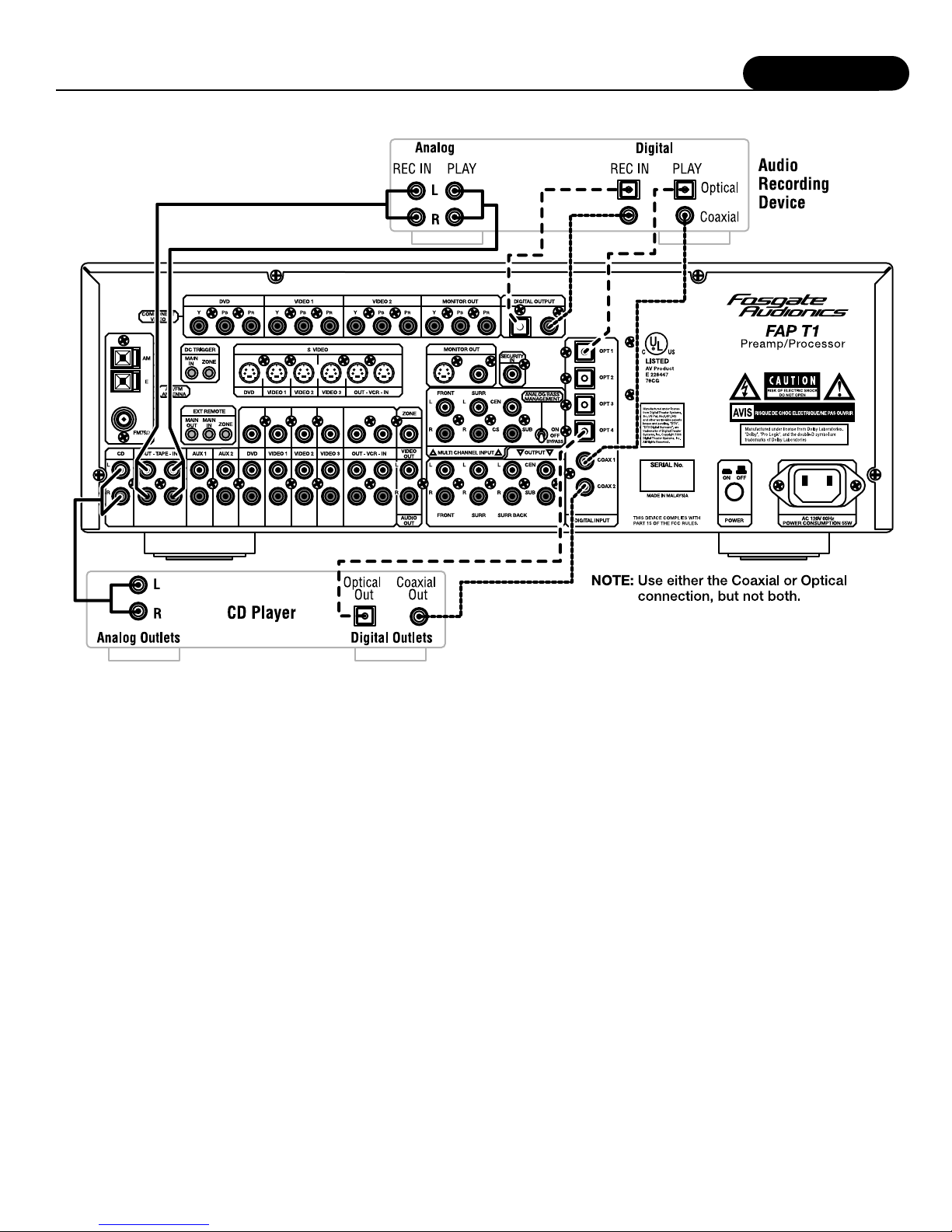
Connecting Audio Components
CONNECTING AUDIO COMPONENTS
CD Player
Analog: Connect the L and R channel outputs on the CD player to
the CD IN jacks on the FAP T1.
Digital: If your CD player has a digital output jack, connect it to
one of the coaxial (COAX 1 or 2) or optical (OPT 1-4) input jacks
on the preamp/processor, depending on the type of connector used
by the CD player. Later, you will con-figure the FAP T1 to use the
specific input that you have chosen. For now, note which digital
input you connected to on your system chart.
Audio Recorder
A recording device such as a cassette deck, MD recorder, DAT
deck or CD recorder can be connected to the FAP T1 using either
or both of the following methods.
Analog: Connect the L and R audio outputs on the recorder
(usually marked PLAY) to the TAPE IN jacks on the rear of the
preamp/processor and connect the L and R audio inputs (usually
marked REC) to the TAPE OUT jacks of the FAP T1.
Digital: If your recorder has a digital output jack, connect it to one
of the coaxial (COAX1 or2) or optical (OPT1-4) input jacks on the
preamp/processor, depending on the type of connector used by the
device. Later, you will configure the FAP T1 to use the specific
input that you have chosen. For now, note which digital input you
connected to on your system chart.
If your recorder has a digital input jack, connect it to either the
coaxial or optical output jack on the preamp/processor. The signal
from the selected digital input source of the FAP T1 will be sent to
the recorder.

Installation
14
Connecting Video Components
CONNECTING VIDEO COMPONENTS
Before making connections to any video devices, understand how
the FAP T1 routes the video portion of the signal through its video
section.
•Any signal that appears at one of the composite video input
jacks (DVD, VIDEO 1, 2 or 3) is automatically sent to the
composite video OUT and VCR OUT jacks, as well as the
S-Video OUT and VCR OUT jacks.
•Any signal that appears at the S-Video input jacks (DVD,
VIDEO 1, 2 or 3) is automatically sent to the S-Video OUT
and VCR OUT jacks, as well as the composite video OUT
and VCR OUT jacks.
•Any signal that appears at the component video (DVD or
VIDEO 1) input jacks is automatically sent to the component
video MONITOR OUT connection only.
NOTE:To provide the greatest signal flexibility, connect all
available types of inputs and outputs from your video
devices. For example, if only the composite video output
(yellow RCA jack) connection is made to your display
device, component sources will not be available, even if
they are connected to the FAP T1.
DVD Player
Composite: Connect the composite video output from the DVD
player to the DVD video input jack on the rear of the FAP T1 using
an RCA-type video cable.
S-Video: If there is an S-Video output on the DVD player, and you
have an S-Video input on your TV or monitor, connect it to the
S-Video DVD input on the rear of the FAP T1 using an S-Video
cable. S-Video delivers a better picture than composite connections
and should be used whenever possible unless you can use
component connections, which deliver better video than S-Video.
Component: If the DVD player has component video outputs,
connect them to the DVD component video input jacks on the rear
of the FAP T1 using an appropriate cable set.
Analog Audio: Connect the L and R channel outputs on the DVD
player to the DVD IN audio jacks on the rear of the FAP T1.
Digital Audio: Connect one of the digital output jacks on the DVD
player to one of the coaxial (COAX I or 2) or optical (OPT 1-4)
input jacks on the rear of the preamp/processor, depending on the
type of connector used by the DVD player. Later, you will
configure the FAP T1 to use the specific input that you haw
chosen. For now, note which digital input you connected to on
your system chart.

Installation
15
Multi-channel Audio If your DVD player supplies a multi-channel
audio output (for DVD Audio or SACD playback), connect the six
outputs (special cable sets for this are available from numerous
sources) from your player to the six input jacks labeled MULTI
CHANNEL INPUT on the rear panel of the FAP T1. Be sure match
the connections—left to left, right surround to right surround, and
so on. If your player includes a built-in Dolby Digital decoder and
has 5.1 channel analog audio outputs we suggest that you do not
use them, but use the digital audio connection and the FAP T1's
internal decoders instead.
If you are connecting a DVD-Audio or SACD player to the FAP T1
using these jacks, you will need to consider the setting for the
Analog Bass Management switch on the FAP T1's rear panel. If
your system uses all full range speakers, set. the switch in the OFF
position. In that setting the signal will be routed directly from the
input jacks to the volume control.
However, if your system uses small,
frequency-restricted satellite speakers, the
switch should be set to the ON position. In
that setting the signals sent to the main
speakers will be cut at 80 Hz and a summed
bass signal will be sent to the subwoofer
output. Note that you should place this
switch in the OFF position if your playback
source includes internal bass management
circuitry.
Video Recorder
A video recording device such as a VCR, PVR (such as a TiVo®,
Replay®, Uiti-mate TV®, DishPlayer®or similar device) or DVD
recorder can be connected to the FAP T1 using the following
methods.
Composite: Connect the composite video output from the
recording device to the VCR IN composite video jack on the rear of
the preamp/processor. Connect the recording device's composite
video input to the VCR OUT composite video jack of the FAP T1
using an RCA-type video cable.
S-Video: If there is an S-Video output on the recording device,
connect it to the S-Video VCR IN input on the rear of the
preamp/processor and connect the S-Video input to the S-Video
VCR OUT using an S-Video cable. S-Video delivers a better picture
than composite connections and should be used whenever possible
unless you can use component connections, which deliver better
video than S-Video.
Component: If the recording device has component video outputs,
connect them to one of the component video input jacks (DVD or
VIDEO 1) on the rear of the preamp/processor using an appropriate
cable set.
Analog Audio: Connect the L and R audio outputs on the recorder
to the VCR IN audio jacks on the rear of the preamp/processor and
connect the L and R inputs of the recorder to the VCR OUT audio
jacks on the FAP T1.
Digital Audio: If your recording device also has a digital audio
output jack, connect it to one of the coaxial (COAX 1 or 2) or
optical (OPT 1-4) input jacks on the rear of the preamp/processor,
depending on the type of connector used by the device. Later, you
will configure the FAP T1 to use the specific input that you have
chosen. For now, note which digital input you connected to on
your system chart.
If your recording device also has a digital input jack, connect
it to either the coaxial or optical output jack on the rear of the
preamp/processor, depending on the type of connector used by
the device. The signal from the selected input source of the
FAP T1 will be sent to the recorder.
Video Display
A video display device such as a television monitor, fixed-pixel
device (plasma or LCD) or video projector can be connected to the
FAP T1 using the following methods.
Composite: Connect the composite video input from the display to
the composite video OUT jack on the rear of the FAP T1 using an
RCA-type video cable.
S-Video: If there is an S-Video input on the display, connect it to
the S-Video OUT jack on the rear of the preamp/processor using an
S-Video cable. S-Video delivers a better picture than composite
connections and should be used whenever possible unless you can
use component connections, which deliver better video than S-Video.
Component: If the display has component video inputs, connect
them to the component video MONITOR OUT jacks on the rear of
the FAP T1 using an appropriate cable set.
NOTE: Since the FAP T1 converts composite video to S-Video and
vice versa, you need only make one of those two types of
connections between the FAP T1 and your video display.
However, when component video connections are used it is
still necessary to make either the composite or S-Video
connections so that you are able to view the on-screen
menus and displays which do not appear on the component
outputs. The FAP T1 does not convert from either composite
or S-Video to component or vice versa.
Satellite Tuner or Television
Composite: Connect the composite video output from the satellite
tuner or television to one of the video input jacks (VIDEO 1,2 or 3)
on the rear of the FAP T1 using an RCA-type video cable.
S-Video: If there is an S-Video output on the satellite tuner or
television, connect it to one of the S-Video inputs (VIDEO 1,2 or 3)
on the rear of the FAP T1 using an S-Video cable. S-Video delivers
a better picture than composite connections and should be used
whenever possible unless you can use component connections,
which deliver better video than S-Video.
Component: If the satellite tuner or television has component video
outputs, connect them to one of the component video input jacks
(DVD or VIDEO 1) on the rear of the FAP T1 using an appropriate
cable set.
Analog Audio: Connect the L and R channel outputs on the satellite
tuner or television to the set of audio input jacks (VIDEO 1, 2 or 3)
directly under the video jack used on the rear of the FAP T1.
Digital Audio: If your satellite tuner or television has a digital
output jack, connect it to one of the coaxial (COAX 1 or 2) or
optical (OPT 1-4) input jacks on the rear of the preamp/processor,
depending on the type of connector used by the device. Later, you
will configure the FAP T1 to use the specific input that you have
chosen. For now, note which digital input you connected to on
your system chart.

Installation
16
FM Antenna
Connect the supplied FM antenna to the terminal labeled FM75Ω.
Do not over tighten as this may damage the connection.
The supplied FM antenna is for indoor use only. For best signal
reception you must fully extend the antenna. Experiment with the
antenna's position to obtain the strongest signal. You can attach it
to a wall or other surface using push pins or similar apparatus.
If FM reception is poor with the supplied indoor antenna, the use
of an amplified indoor or outdoor antenna is recommended.
NOTE:You can only connect a 75Ωtype FM antenna to the
FAP T1. If you choose to use an antenna other than the
one supplied, be sure to verify that it has the correct type of
connector or that you obtain an appropriate adapter.
Try to ovoid using the same antenna for both FM and TV
reception since the signals can interfere with each other. If
you must use a com-mon FM/TV antenna, be sure that you
install an splitter to separate the two signals.
AM Antenna
Connect the AM antenna to the terminals labeled AM and E(arth)
on the rear panel of the preamp/processor. Start by pressing the
lever on the side of one of the terminals to the right. Next, insert
one of the antenna wires into the opening. Finish by returning the
lever to the up position, securing the wire. Do the same for the
other wire to complete installation.
AM
Loop
Antenna
FM Antenna
Connecting an External Amplifier
IMPORTANT:Before attempting to plug any jacks into any power
amplifier verify that the power amplifier is turned off
and/or disconnected from the AC mains. Failure to do
so can potentially result in severe damage to your
amplifier and loudspeakers.
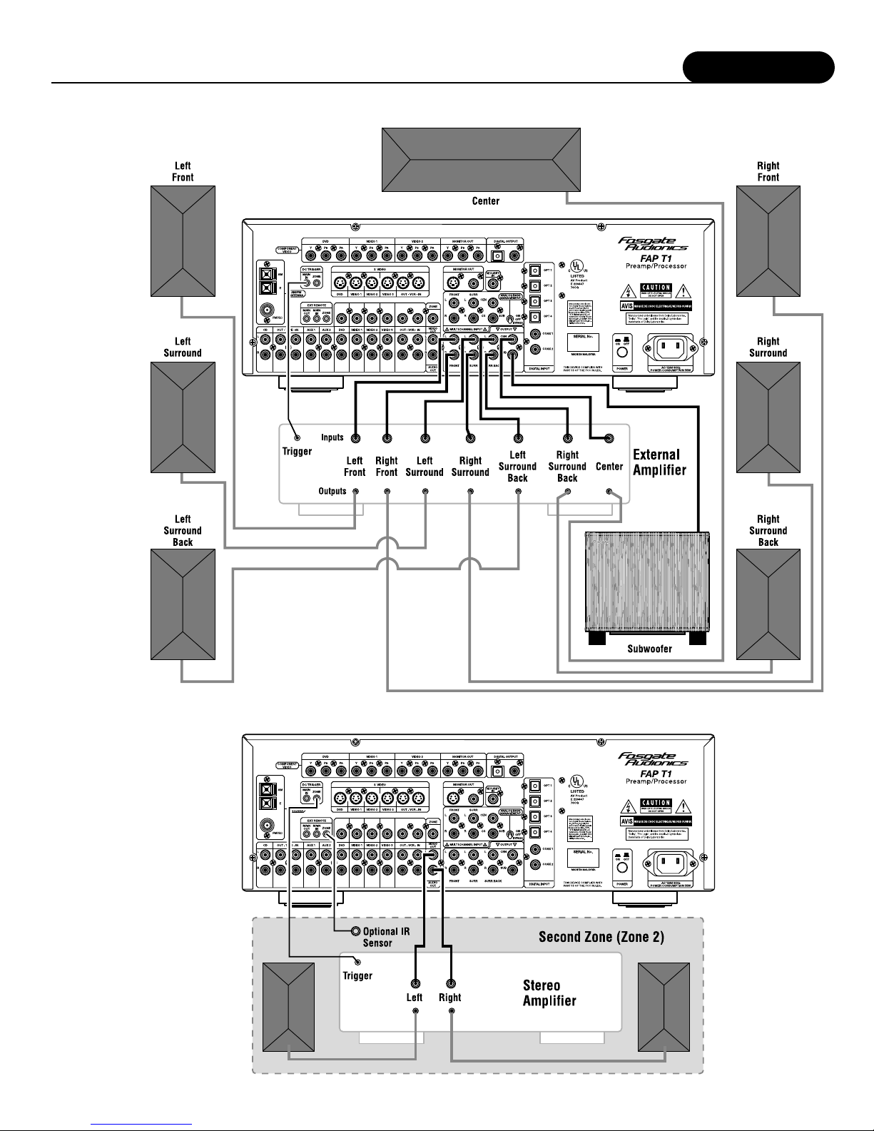
Use the audio jacks labeled OUTPUT to connect the FAP T1 to an
external power amplifier such as the Fosgate Audionics FAA 1000.5
Power Amplifier. The FAP T1 can output up to 7.1 channels of
sound (seven satellite and one subwoofer channel) depending on
source components and material.
The output jacks supplied by the FAP T1 are: left Front, Center,
Right Front, Left Surround, Right Surround, Left Surround Back,
Right Surround Back, and Subwoofer.
Be sure to verify that the correct outputs are connected to the
appropriate input jacks (Left Front to Left Front, Right Surround
Back to Right Surround Back, etc.)
When a powered subwoofer is used, connect the Subwoofer output
jack to the Line Input jack on your subwoofer and follow any
specific connection and/or configuration, instructions supplied with
the subwoofer. If your subwoofer is a passive speaker, connect the
subwoofer output jack on the FAP T1 to the input of the amplifier
used to power the subwoofer, and then connect the subwoofer
speaker itself to the amplifier.
Second Zone (Zone 2)
Use the L and R channel ZONE OUT audio jacks to connect the
FAP T1 to the analog audio inputs of an external amplifier or other
audio component in a second zone. The signal present will reflect
the input selection of the FAP T1. This may be adjusted using the
Zone Menu or the MULTI button on the remote control.
Power Control Connections
The DC TRIGGER jacks are used to remotely turn-on other devices
in your system when the FAP T1 is powered on. Power is applied
to the MAIN Trigger Output jack when the FAP T1 is turned on
from the Standby Mode. We recommend that this jack be used to
turn on a compatible power amplifier such as those available from
Fosgate Audionics, but it may also be used to activate compatible
products such as projection screens or motorized blinds.
Connect a 3.5mm mono mini-plug between the DC Trigger MAIN
jack on the rear panel of the FAP T1 and the low voltage trigger
jack of the device to be controlled to enable remote turn-on of
that component. The ZONE Trigger jack is activated when the
Multi-room system is turned on and should be used for control of
amplifiers used to power the speakers installed in the remote zone.
It will remain activated as long as the Multi-room system is on,
even when the FAP T1 is in the Standby mode for the main room.
Remote Control
The EXT REMOTE jacks allow you to extend the on-board
remote control sensor on the FAP T1's front panel so that you may
continue to control the FAP T1 even when it is installed behind
solid or smoked cabinet doors or when the front panel sensor is
otherwise not visible to the remote control.
To extend the remote sensor connect an optional remote sensor to
the MAIN jack.
The ZONE jack is provided to enable remote control of the
FAP T1's multi-zone system through the use of an optional remote
sensor in the second zone. Connect the sensor to the ZONE jack
using a 3.5mm mono mini-plug and the wiring specified by the
sensor's manufacturer.
Power Connection
Insert the supplied power cord into the AC input of the rear panel
of the preamp/processor. Do not use a power cord other than the
one supplied with the FAP T1. It's designed for use with the
FAP T1 and should not be used with any other device.
CAUTION: Before you plug the power cord into an AC
wall outlet, ensure all connections to the
preamp/processor have been made correctly.
WARNING: Never disconnect the power cord from the
FAP T1 while the other end is plugged into
an AC outlet. Doing so may cause an electric
shock. Always connect power by plugging
into the AC outlet last and disconnect by
unplugging from the AC outlet first.
Installation
17
Connecting to an External Amplifier in a Second Zone (Zone 2)
Connecting an External Amplifier
System Setup
18
At this point you should have made all the necessary physical
connections between the FAP T1 and your source equipment,
amplifiers and speakers. All that remains is to properly configure the
system to reflect your specific equipment and room characteristics.
To turn the FAP T1 on:
1. Plug the cord into an AC wall outlet or UL approved power
strip or surge protection device.
Make certain that the AC power cord supplied with the FAP T1
is firmly inserted into the socket on the unit's rear panel.
2. Press the rear panel POWER switch to the On position to
set the FAP T1 to Standby mode.
The Standby Indicator on the Front Panel will light up.
3. Press the front panel Standby Power button to turn on the
FAP T1 or press the AUD button on the remote control.
The FAP T1 DISPLAY will light up and the standby indicator
will turn off.
Navigating the Setup Menus
Setup of the FAP T1 can be performed from the front panel of the
unit, or by using the remote control. Information is shown on the
FAP T1 Display, or the On Screen Display (OSD). All selections
are made using a combination of the following buttons:
Front Panel: The MENU, Navigation ( , , and ) and
(Select) buttons left of the FAP T1 Display
Remote Control: The MENU, Navigation ( , , and ) and
SEL/PLAY buttons in the center of the remote.
These buttons will be referred, unless otherwise specified, when
navigating the Setup Menus.
The following example demonstrates how to navigate the FAP T1
menu system in general using the Speaker Configuration menu as
an illustration. For detailed information on a specific part of the
setup process, consult the pages relating to that topic.
To use the FAP T1 menu system:
NOTE:The following selected menus appear on the FAP T1
Display and the OSD (On Screen Display)
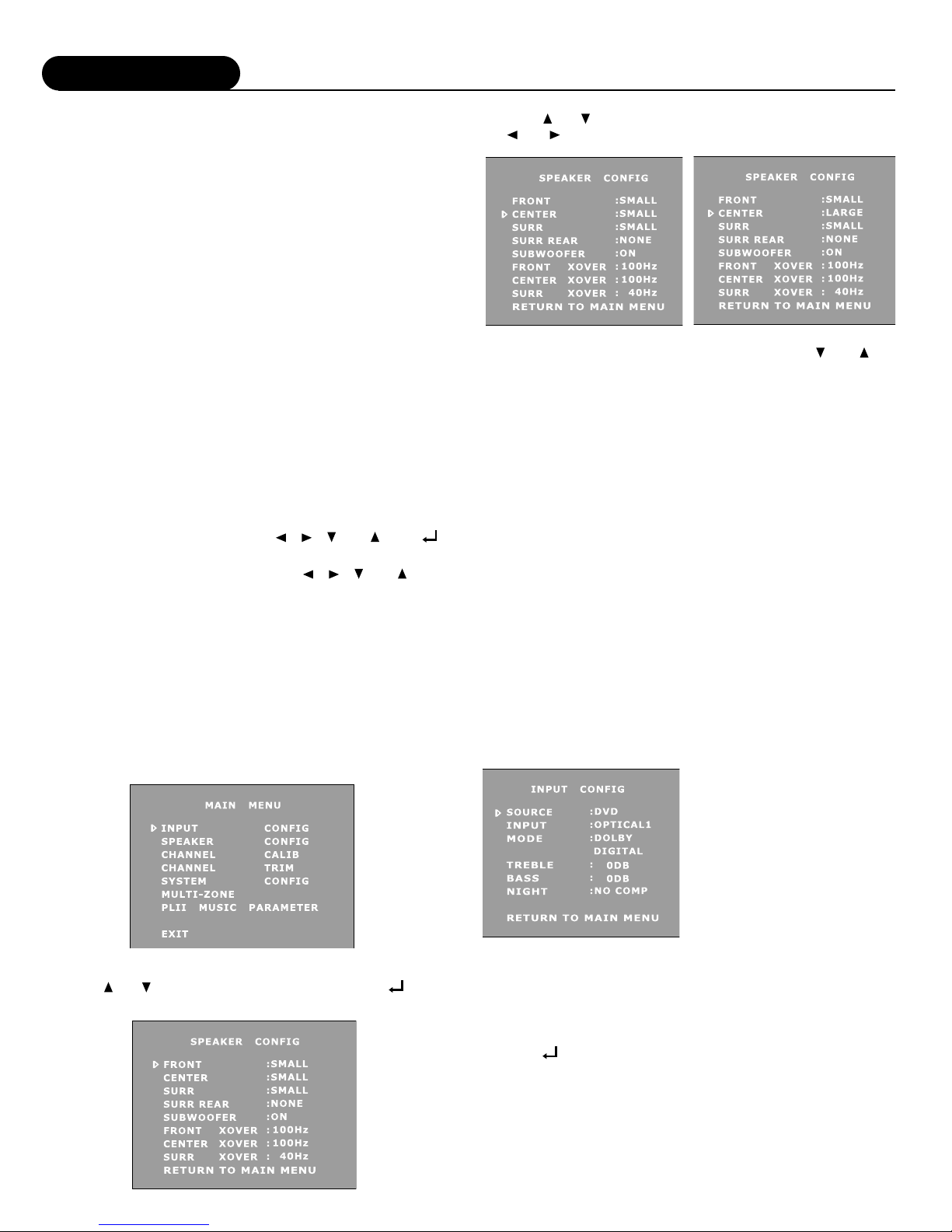
1. Press the MENU button to display the Main Menu.
2. Press or to select a Setup menu. Then press
(Select) to enter into the menu.
3. Press or to select the item to be adjusted. Then press
or to adjust a selected item.
Once you have made your selections, you can use the and to
return to the Main Menu and/or exit the menu system. Alternatively,
pressing the MENU button once will return you to the Main Menu.
Pressing the MENU button a second time will exit the menu system.
Note that the menus will remain visible on the FAP T1 Display and
OSD until you exit the menu system.
IMPORTANT:When viewing static images such as on screen menus
or video game images using a CRT-based projector,
plasma display or direct-view CRT monitor or
television, there is a risk of permanently 'burning in"
the image. Do not leave these images on for an
extended period of time. This type of damage is not
covered by the Fosgate Audionics FAP T1 warranty.
INPUT CONFIGURATION – Setup and Selection
Before calibrating your FAP T1 and adjusting loudspeaker setup
and configuration, you should first set up the sources connected to
it. You will make your selections using the Input Configuration
menu, shown below.
NOTE:The following selected menus appear on the FAP T1
Display and the OSD (On Screen Display)
Figure 1
Because of the extensive options
available for each input source,
we strongly recommend you use
the chart at the end of this manual
to record the settings for each
input and component. Later, if
you re-configure your system, this
chart will help avoid confusion.
To configure an input:
1. Press the MENU button to enter the Main Menu.
The Main Menu appears and the cursor should be pointing to
INPUT CONFIG.
2. Press (Select) to enter the Input Configuration menu.
The Input Configuration menu appears and the cursor should be
pointing to SOURCE.

System Setup
19
3. Use the and buttons to change the Source you wish
to configure.
The Source choices appear as follows as you scroll through
them:
DVD > VIDE01 > VIDE02 > VIDE03 > VCR >
TUNER (FM) > TUNER (AM) > CD > TAPE > AUX1 > AUX 2
You can scroll in either direction using the and buttons.
4. Press the button once to select INPUT.
5. Use the and buttons to change the Input for that
source.
The input choices appear as follows as you scroll through them:
ANALOG > OPTICAL1 > OPTICAL2 > OPTICAL3 >
OPTICAL4 > COAXIAL1 > COAXIAL2
You can scroll in either direction using the and buttons.
If you connected the source to the Analog inputs, select:
ANALOG.
If you connected the source to one of the Optical Digital inputs,
select the appropriate one by choosing: OPTICAL 1, 2, 3, or 4.
If you connected the source to one of the Coaxial Digital inputs,
select the appropriate one by choosing: COAXIAL 1 or 2.
NOTE:Always connect and configure the digital input source
option if available from the specific component, as this will
provide maximum performance and best sound quality.
Remember that you can always return to any menu to change
your selection, should that be required.
6. Press the button once to select MODE.
7. Use the and buttons to change the Mode for that
source.
The available surround modes appear as follows as you scroll
through them:
PLII CINEMA > PLII MUSIC > DOLBY PRO LOGIC >
7 STEREO > 5 STEREO > STEREO > PLII CINEMA CS
> PLII MUSIC CS > DTS > DTS NEO:6 CINEMA >
DTS NEO:6 MUSIC > DOLBY DIGITAL >
DOLBY DIGITAL EX > DTS ES
You can scroll in either direction using the and buttons.
You should choose a surround mode to be the default for this
source. Please refer to the table on page 7 for a detailed listing
of all options. Remember that all available mode options can be
selected for a Digital input source, but certain modes will not be
available through the Analog input for that source.
Selecting the default mode will not exclude other modes of
surround decoding. In fact, certain digital signals (Dolby Digital,
DTS, some Dolby Digital EX, and others) contain a special
digital "flag" that tells the FAP T1 to switch to that surround
mode. When the FAP T1 receives one of these bitstreams it
will switch to that mode of operation. Additionally, you can
manually cycle through the available modes while the source is
playing to choose the one you wish to use.
8. Press the button once to select TREBLE
9. Use the and buttons to adjust the Treble.
Treble boost can be adjusted from -6dB to +6dB in 2dB
increments (default is 0dB).
10.Press the button once to select BASS.
11.Use the and buttons to adjust the Bass.
Bass boost can be adjusted from -6dB to +6dB in 2dB
increments (default is 0dB).
NOTE:Any tone control setting you make in this mode are global,
and will affect all input sources and all output channels.
They will remain in effect until you go back into the setup
menu and change them or change them using the TONE
button on the remote control.
12.Press the button to select NIGHT.
NOTE:This option only operates with a Dolby Digital or Dolby
Digital EX source and one of these modes is active.
This option allows you to set the amount of Dynamic Range
Compression used when the FAP T1 is placed into the NIGHT
mode. This mode can also be selected by pressing the NIGHT
button on the remote control.
There are two types of automatic compression control built into the
Dolby Digital process. Compression makes the loud parts softer and
the soft parts louder to reduce the difference between the two.
One type of compression is most useful for situations such as late
night viewing of programs with a wide dynamic range (like many
action movies) that might disturb others in your home. This function
can also be used to provide compression for program material that
may require enhancement of overall intelligibility (such as some
older soundtracks). Another feature provided by this option is the
necessary peak limiting required to avoid signal overload when
"down-mixing" functions are selected.
The second variable provides additional peak limiting to allow
overall average program level to be increased by adding even more
compression to the signal.
These two algorithms can provide sufficient overall gain reduction to
allow even wide dynamic range soundtracks with very soft parts and
very loud parts to maintain good audibility at low volume levels.
In most cases a minimum amount of dynamic range reduction is
automatically included in the bitstream to ensure safe down-mixing.
13.Use the and buttons to select a Dynamic Range
option you prefer for the Night setting,
NO COMP This option leaves the compression at 0% change.
DR COMP1 This option increases the compression by 25%.
DR COMP2 This option increases the compression by 50%,
DR COMP3 This option increases the compression by 75%.
DR COMP4 This option increases the compression by 100%.
Each option increases the amount of Dynamic Range compression
to the signal. Depending on your family, neighbors, circumstances,
and the overall volume you wish to achieve, we recommend you
start with DR COMP1 or DR COMP2 as your initial setting. You
will have to experiment with program material and your personal
preferences to determine what is acceptable and best for you.
14.Press the button to select RETURN TO MAIN MENU.
15.Press the (Select) or MENU button to return to the Main
Menu, or press the MENU button twice to exit the menu
system.
NOTE:Except for the input source and surround mode, the settings
chosen during this input setup process are universal and
apply to all sources. You will need to correctly set each
digital source to the appropriate input and select a default
surround mode for each source connected to your FAP T1.
Once you have completed these selections, proceed to
the next step: configuring your loudspeaker setup and
calibrating your system.
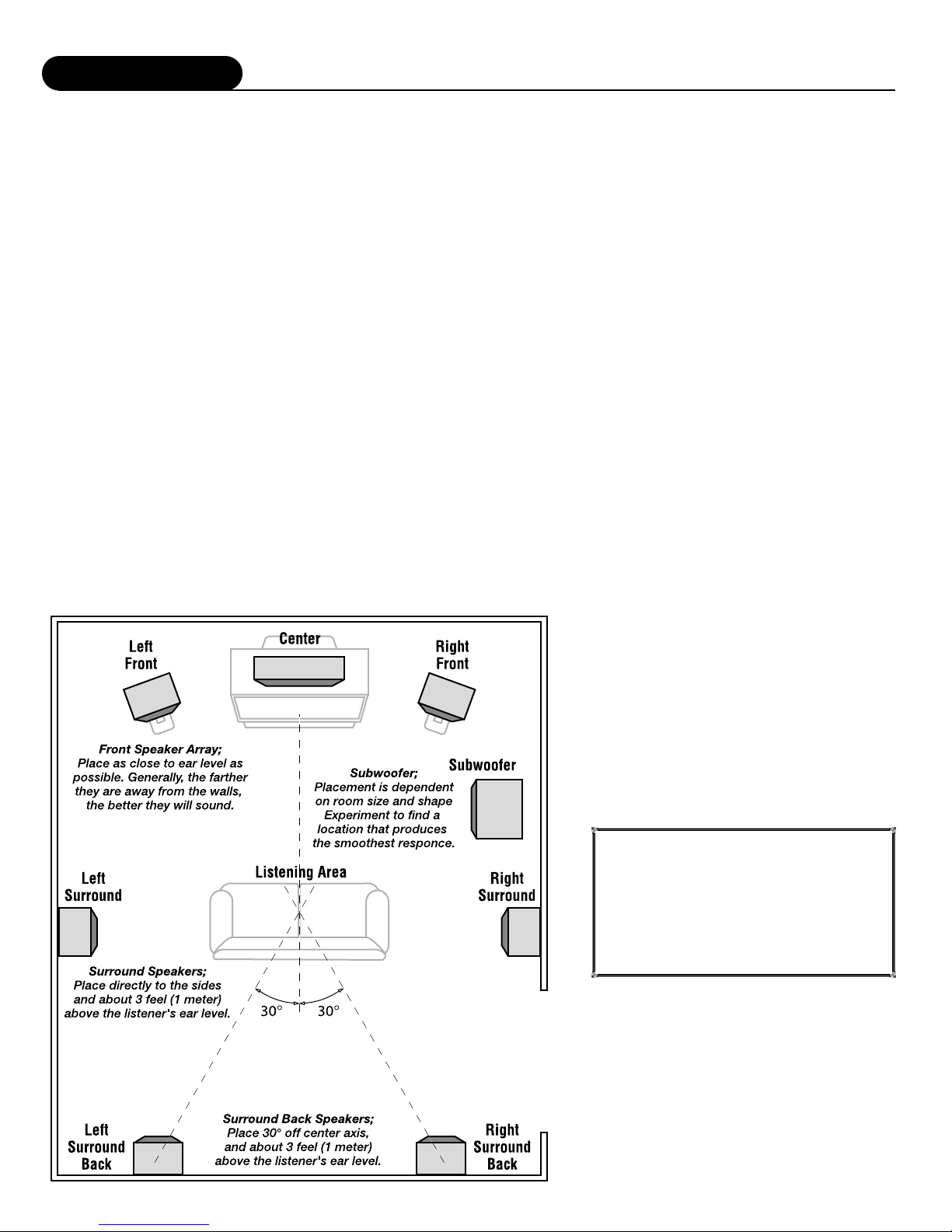
System Setup
20
SPEAKER CONFIGURATION –Setup and Selection
You are now ready to configure the FAP T1 for your particular
loudspeaker system. Before proceeding please read the following
information carefully:
Speaker Placement
The best speaker placement for your particular room will depend
on its size, furnishings, seating arrangement, the acoustical
properties of the space, including wall type, coverings, and various
other factors.
Due to the complex nature of these variables it is impossible to
recommend any one-size-fits-all placement. You may well have to
experiment with various placement options to determine the best
configuration for your specific situation. Please note that, the
configuration and placement of your speakers is critical for creating
the best possible surround sound playback.
Here are some basic recommendations you should consider when
positioning your speakers.
Front left, center and right speakers:
•These speakers should be placed at the same relative height
from the floor and a similar distance from any walls. Most
speakers sound best when located with the tweeter at ear
height when you're seated. Typically, the further away from
the walls the speakers are, the better they will sound.
•Insure that the speakers are aimed at the listener's ears within
your chosen seating position.
Surround left and right speakers
•Place these speakers so that their height is approximately
3 feet (1 meter) higher than that of the listener's ears if feasible.
Surround back left and right speakers
These speakers are required for Surround EX, DTS-ES, DTS NEO:6
and Cirrus Extra Surround playback.
•Place these speakers behind the listener so that the angle between
each speaker and the listener is approximately 30 degrees.
•Place these speakers so that their height is 3 feet (1 meter)
higher than that of the listener's ears.
Note on dipole surround loudspeakers: Most dipole surround
speakers have an arrow which indicates their proper
orientation relative to your video display/screen. Dipoles
placed on side walls should have the arrows pointing
forward. Dipoles placed on a rear or back wall should
have the arrows pointing towards each other to achieve the
correct acoustical image in the room.
Subwoofer
Subwoofer placement can frequently be a trial and error affair as bass
energy set up "standing waves" in most every room. These standing
waves can cause areas with too much bass, areas with too little bass,
and areas in between. You may have to move the subwoofer and or
the prime listening area to improve the bass response. Be aware that
every surface you place the woofer close to (one wall, floor, two walls
in a comer) will increase the overall apparent bass in the room. But
this can potentially lead to boomy and muddy
sounding bass.
When connecting any speakers, be sure to read the
instruction manuals that came with the product and
check your power amplifier's instruction manual for
proper hook-up of the loudspeakers.
IMPORTANT: The FAP T1 is shipped from
the factory in the following
default mode:
Output Configuration 7.1
Speaker Size Small
All Crossovers 100Hz
Table of contents
Other Fosgate Audionics Amplifier manuals


