Fox RZR XP1000 User manual

2.5 PODIUM-X
AFTERMARKET SHOCK
OWNER’S MANUAL
PODIUM RC2
RZR XP1000
OWNER’S MANUAL

Reference print standards 604-00-300 rev
A 605-01-108 rev B Pg. 2
CONTENTS
CONGRATULATIONS .............................................................................................. 3
CONSUMER SAFETY .............................................................................................. 3
UNDERSTANDING THE PODIUM RC2 .................................................................... 4
INSTALLING YOUR SHOCKS .................................................................................. 5
READING THE SPRING RATE ................................................................................ 7
SETTING THE RIDE HEIGHT .................................................................................. 7
ADJUSTING SPRING CROSS OVER ...................................................................... 8
DUAL SPEED COMPRESSION (DSC) ................................................................... 11
REBOUND ADJUST ............................................................................................... 12
MAINTENANCE ...................................................................................................... 12
REBUILD / SERVICE .............................................................................................. 13
WARRANTY ............................................................................................................ 13
SERVICE ................................................................................................................ 13

605-01-108 rev B Pg. 3
CONGRATULATIONS
Thank you for choosing FOX Podium shock absorbers for your UTV. In doing so, we believe that you have
chosen the finest suspension products in the world.
FOX shocks have been designed, tested and manufactured in the USA for more than 35 years.
As a consumer and supporter of FOX products, you need to be aware of the importance of setting up your
shocks correctly to ensure maximum performance. This manual provides step-by-step instructions on how
to set-up and maintain your shocks. It is a good idea to keep your proof of purchase with this manual and
refer to it for service and warranty issues.
This manual does not contain step-by-step shock rebuild instructions. Rebuilding should be carried out by
an authorized FOX service technician.
CONSUMER SAFETY
WARNING: Driving a UTV can be dangerous and can result in death or serious injury.
Take your responsibility for yourself and others seriously, and read the following safety tips:
-
Keep your vehicle and its suspension systems in optimal working condition.
-
Always wear protective clothing, eye protection and a helmet.
-
Know your limits and drive within them!
The FOX coil-over shock contains a high pressure nitrogen charge. The shock should only be opened by
an authorized FOX technician.
WARNING: Opening a nitrogen pressurized shock can be dangerous and can result in SERIOUS
INJURY OR DEATH. NEVER attempt to disassemble the damper of your coil-over shock. Do not
puncture or incinerate the shock absorber or damper portion. Always wear eye protection when installing
or adjusting your shock absorber

APPLICATIONS Dunes / Race and
Trail 605-01-108 rev B Pg. 4
UNDERSTANDING THE PODIUM RC2
•Body
!Large diameter 6061-T6 smooth bore seamless aluminum body allows for greater damping force
capability while allowing the shock to run at lower overall temperatures.
!Increased oil volume allows for reduced fade and increased durability.
!Genuine Kashima Coating for less friction and reduced heat.
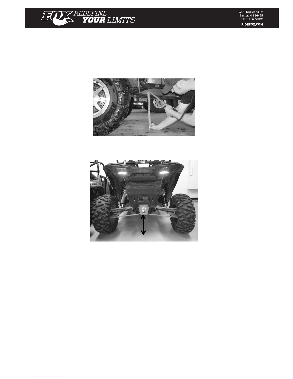
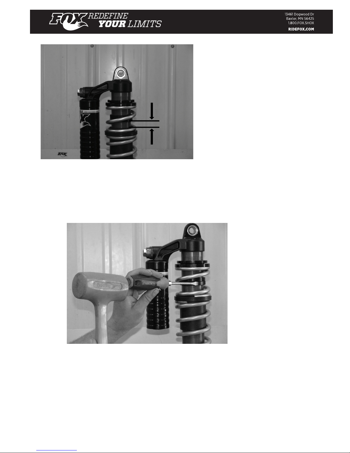
•Spring Adjustment
oPreload adjustment
oCrossover ring adjustment
•High-Speed Compression Adjuster (22 position)
oThe high-speed compression (HSC) adjuster mainly affects compression damping
during medium-to-fast suspension movements such as steep jump faces, harsh flat
landings and aggressive whoops. The goal is to run as little high-speed compression
damping as possible without bottoming.
•Low-Speed Compression Adjuster (24 position)
oThe low-speed compression (LSC) adjuster primarily affects compression damping
during slow suspension movements such as G-outs or smooth jump landings. It also
affects wheel traction and the harshness or plushness of the vehicle (note that low-
speed has nothing to do with the speed of the vehicle). Choose an LSC setting that
gives good body control without causing excessive harshness or loss of traction.
•Rebound damping Adjustment (22 position)
oRebound damping controls the rate at which the shock returns after it has been compressed.
The proper rebound setting is a personal preference and changes with rider weight, riding style and
conditions.
•Teflon-Lined, Heat-Treated, Alloy Steel Spherical Bearings
•Hard-Chrome-Plated Alloy Steel Shaft
•Bottom-Out Control Technology:
oBottom-out cup provides additional end-of-stroke compression damping for those really
hard hits.
!Offers up to 30 percent more damping at the final 25 percent of travel.
This allows the shocks to be tuned to give improved small- bump compliance in the upper
portion of the stroke while still maintaining the ability to absorb huge impacts effectively.

605-01-108 rev B Pg. 5
INSTALLINGYOURSHOCKS
Your shock absorber should come supplied with the correct reducers pre-installed to mount the shock to
your vehicle.
WARNING: Contact FOX if these reducers do not fit correctly. Correct shock mounting is critical for correct
operation and for your safety.
Front Shocks:
•Raise the front of the vehicle with a jack, support with jack stands and remove the stock shock
absorbers. Document the reservoir orientation so the FOX replacement shocks mount in a similar
manner so reservoirs are oriented toward the rear of the vehicle.
•Install the upper mounting bolt through the shock eyelet and upper suspension mount.
•Install the lower mounting bolt through the shock eyelet and lower suspension mount.
•Tighten the upper and lower shock bolts. Follow the Manufacturer’s recommended torque specifications.
•After shocks have been tightened to the torque spec as listed, remove the jack stands and lower the
vehicle.
Rear Shocks:
•Raise the rear of the vehicle with a jack, support with jack stands and remove the stock shock
absorbers along with the reservoir hose clamps and isolators.
•In order to mount the FOX shocks, the plastic cover that goes around the stock shock hose will need to
be removed and stored, as it will not be needed.
•Install the upper mounting bolt through the shock eyelet and upper suspension mount.
•Install the lower mounting bolt through the shock eyelet and lower suspension mount.
•Tighten the upper and lower shock bolts. Follow the Manufacturer’s recommended torque specifications.
•Maneuver the reservoir and hose through the opening left by the cover that had been removed.
•Position the reservoir as shown and install the clamp cover and qty. 4 ¼-20 X 1.5” socket head cap
screws. Tighten in a crisscross pattern and torque to 15 ft-lbs. be sure to use blue Loctite® 242 to
ensure screws do not come loose.
•After shocks have been tightened to the torque spec as listed, remove the jack stands and lower the
vehicle.

605-01-108 rev B Pg. 6
Checking the Ride height
•Once the vehicle is on the ground, the scrub needs to be taken out of the tires so the ride height can be
measured. In order to remove the scrub the vehicle needs to be driven at least 10 feet.
Measure the front and rear ride heights as shown on a flat and level surface.
FRONT
The FRONT should always be set about ½" higher than the REAR.
REAR
Increase spring preload to increase vehicle ride height.
WARNING: Be sure not to add too much pre-load into the coil spring. Doing so may result in coil-bind, leading
to spring failure and potentially injury or death. If you are at maximum preload and need more ride-height,
contact FOX for a stiffer spring.
•The distance from the ground to the front outer frame rail should be between 13.5-13.75”
•The distance from the ground to the rear frame rail should be between 13.25-13.5”
The optimum vehicle ride height will be determined by exact vehicle configuration and usage.
Individual vehicles can vary significantly in weight so it is important to check the ride height when you first
install your shocks. For example, if you have added accessories to your vehicle that increase the weight, you
may need to consider alternate spring rates.

605-01-108 rev BPg. 7
READING THE SPRING RATE
FOX coil-over shocks only use quality, high stress race springs. The springs are a shot-peened, heat-treated
chrome-silicon material, designed to give maximum travel and minimum weight. They are preset to ensure
they don’t sag over time.
TIP: The springs are typically labeled: XXXX-
XXX-XXXX
For example: 1000-250-0225
The first four digits indicate the spring free length: 1000 = 10.00 inches
The middle three digits indicate the spring free internal diameter: 250 = 2.50 inches The last four digits
indicate the spring rate: 0225 = 225 lb-in
SETTING THE RIDE HEIGHT
All FOX coil-over piggyback shocks feature adjustable spring preload. Your vehicle performance is sensitive
to ride height variations.
P/N 398-00-393
WARNING: Do not add excessive amounts of preload into the coil spring. Doing so may result in coil-bind,
which could lead to spring failure and potential injury or death. To check coil-bind, put several zip-ties around
individual coils. If they break or show contact, there is excessive preload. If you are at maximum preload and
need more ride height, contact FOX for a stiffer spring.

605-01-108 rev B Pg. 8
ADJUSTING SPRING CROSSOVER (DUAL SPRING ONLY)
The spring crossover point is an important tuning parameter. A softer initial spring rate
offers improved traction and hook-up while a higher spring rate deep into travel helps to resist bottoming on
jump landings.
As a rough guideline, the spring crossover point should be as deep into travel as possible without
experiencing excessive bottoming. The crossover point is defined as a percentage of the total shock travel.
The factory setting for the spring crossover point is 55 percent. This means that a 5-inch travel shock would
have the crossover point at 2.75 inches (5.0 inches x 0.55) into the shock travel.
In order to calculate your spring crossover ring placement, you need to know four important pieces of
information:
1. Metal-to-metalshocktravelininches(measurebeforespringinstallation).
2. Main spring rate (lb-in) - marked on spring (see Reading the Spring Rate).
3. Tender spring rate (lb-in) - marked on spring (see Reading the Spring Rate).
4. Desired crossover point (as a percentage).
The shock travel is the exposed length of the shaft (including the bump stop) when the shock is fully
extended. It may be easiest to measure before you install the shock.
Some shocks use external spacers below the bump stop to limit travel. Do not include the spacer length as
part of the travel.
The crossover point is a tunable parameter. It should be between 45 and 65 percent.
SETTING THE CROSSOVER POINT (shock has been removed from vehicle for display purposes)
NOTE: ALWAYS W EAR EYE PROTECTION W HEN WORKING WITH SHOCK ABSORBERS.
STEP 1 Set ride height as described on page five.
STEP 2 Once you have established the correct preload, jack up the UTV and place on a stand to keep the
wheel off the ground. The shock should be fully extended.
SHOCK TRAVEL

605-01-108 rev B Pg. 9
STEP 3 Use a hammer and flat blade screwdriver, to loosen the crossover rings.
STEP 4 Determine the Spring Correction Factor using the following table:
STEP 5 Use the following formula to calculate crossover ring placement:
Crossover Ring Placement = Shaft Travel (in.) x Crossover Point x Spring Correction Factor
EXAMPLE
•
A 5.2-inch travel shock with a 225 lb-in main spring and an 800 lb-in tender spring.
•
The crossover point is set at 55 percent.
•
From the table above, the spring correction factor is 0.220.
•
From the above formula, the crossover ring placement value is 5.2 x 0.55
x 0.220 = 0.629 inches.
IN THE ABOVE EXAMPLE, 55 PERCENT IS WRITTEN AS 0.55.

605-01-108 rev B Pg. 10
Crossover ring
placement
value
should
match the
distance from
the
top of the
spring
coupler
to the
bottom of
the
crossover
ring. Example
.629 inches
You may need a small, flexible ruler or measuring device to accurately determine the crossover ring location.
Another useful way of measuring is to count the threads on the body (the thread pitch on the body is 14
threads per inch). If you know the crossover ring location, multiply by 14 to get the number of threads
between the spring coupler and crossover ring. In the example above, 0.629 inches = 0.629 x 14 = 8.8
threads.
Changing the spring preload, tender or main spring free-length or rate
will mean that you need to reset
the crossover ring placement.
STEP 6 Adjust the crossover (as shown on the previous page) so that its distance from the spring coupler is
equal to the crossover ring placement value calculated in Step 5. Lock the crossover rings together
once complete with flat-bladed screwdriver and hammer.
STEP 7 Remove the UTV from the stand.
.629”

605-01-108 rev B Pg. 11
DUAL-SPEED COMPRESSION (DSC) ADJUST
The FOX DSC valve is an option on coil-over shocks and gives the ability to externally adjust the
damping. The DSC has about 24 clicks of low-speed adjustment and about 22 clicks of high-speed
adjustment. The factory setting is 12 / 12. The performance of the shock at this setting is close to
the performance of the non- adjustable shock and is a good all-around setting. The DSC valve gives the
driver the ability to tune the shock for different terrain / personal preference on either side of this setting
(softer or stiffer).
LSC (LOW-SPEED COMPRESSION) ADJUSTMENT
The LSC is adjusted using a flat-blade screwdriver in the middle of the adjuster. More damping = stiffer =
clockwise
LSC primarily affects the compression damping during slow suspension movements such as G-outs
or smooth jump landings. It also affects wheel traction and the ride comfort of the vehicle.
Choose a LSC setting that gives good body control (roll in corners, dive under braking, squat under
acceleration, etc.) without causing excessive harshness or loss of traction.
The graph below shows the typical range of adjustability for the LSC adjuster from full-firm to full-soft
with the HSC adjuster held constant at 10 clicks out.
HSC (HIGH-SPEED COMPRESSION) ADJUSTMENT
The HSC is adjusted using a 17 mm socket More
damping = stiffer = clockwise
The HSC adjuster affects the compression damping during medium-to-fast suspension movements such as
steep jump faces, harsh flat landings and aggressive whoops. The goal is to run as little high-speed
compression damping as possible without bottoming. The graph below shows the typical range of
adjustability for the HSC adjuster from full-firm to full-soft with the LSC adjuster held constant at 10 clicks:
LSC ADJUSTMENT RANGE HSC ADJUSTMENT RANGE
FOX DSC VALVE PERFORMANCE
Low-Speed Adjuster dialed full soft to full firm
Hi-Speed Adjuster held constant at 10 Clicks
-500
-400
-300
-200
-100
0
020 40 60 80 100 120 140
Velocity (in/s)
Force (lbf)
FOX DSC VALVE PERFORMANCE
Low-Speed Adjuster held constant at 10 Clicks
Hi-Speed Adjuster dialed full soft to full firm
-600
-500
-400
-300
-200
-100
0
020 40 60 80 100 120 140
Velocity (in/s)
Force (lbf)
FOX DSC VALVE PERFORMANCE
Low-Speed Adjuster dialed full soft to full firm
Hi-Speed Adjuster held constant at 10 Clicks
FOX DSC VALVE PERFORMANCE
Hi-Speed Adjuster dialed full soft to full firm
Low-Speed Adjuster held constant at 10 Clicks

605-01-108 rev B Pg. 12
REBOUND ADJUST
The Rebound Adjust feature on FOX coil-over shocks gives the ability to externally adjust the shock rebound
damping. Adjustments are made using a small flat- bladed screwdriver on the eyelet at the end of the shock
shaft.
For slower rebound, turn the screw clockwise.
The rebound adjuster has about 22 clicks of adjustment. The factory setting is 12 clicks out. The
performance of the shock at this setting is close to the performance of the non- adjustable shock and is a
good all-around setting.
The rebound damping affects how quickly the shock extends (rebounds). This adjustment affects both low-
and high-speed rebound damping. It will affect how quickly the vehicle rolls / pitches under acceleration and
braking and will also affect how quickly the wheels rebound when travelling through a series of large bumps.
The optimum rebound setting is usually found with the minimum damping required to give acceptable chassis
control. Excessive rebound damping will typically be felt as the suspension "packing." This can often be seen
or felt as the vehicle travels through a series of similar-sized, successive bumps. It works well for the first two
or three bumps and then bottoms hard on the third or fourth. This is because the wheels aren't rebounding
quickly enough, and the wheels "pack" into compression.
For tight, flat surfaces you may like to run more rebound damping for more chassis control. For high-speed
open desert running, you may prefer to run less rebound damping for maximum traction.
MAINTENANCE
PROPER INSPECTION AND MAINTENANCE IS ESSENTIAL TO MAINTAIN THE APPEARANCE AND
PERFORMANCE OF YOUR SHOCKS.
To avoid corrosion, you should keep the shock and spring clean and free of dirt or water.
It is important to keep the shock shaft clean and free of mud. The wiper seal will clean
deposits from the shaft but the shock won’t necessarily fully compress every time. This
means you could accumulate dirt at the bottom of the shaft and underneath the jounce
bumper. Make sure you clean these areas completely to prevent shaft corrosion.
Avoid using a high-pressure washer near the shaft seals or adjusters, as this could drive dirt inside the
shock.
Make sure the ends of the spring and shock threads are clean and free of dirt before adjusting the preload
ring — this will make the adjustment easier and reduce wear.
Ideally the shocks should be clean around the adjusters when changing the damping setting (if fitted). A
small blast of contact cleaner or brake cleaner before making adjustments will keep these parts clean and
operating smoothly for years.

605-01-108 rev BPg. 13
REBUILD / SERVICE INTERVALS
Just like the oil in your car engine, the oil in your shock absorber breaks down over time and must be replaced.
The service interval depends on how frequently and severely the vehicle is driven. For optimum performance
racing applications the shocks may require rebuilding every 10-20 hours of use. In non-racing environments
to keep your shocks performing at optimum performance we recommend at least every 100-200 hrs of use
.
WARNING: Shock rebuilds take specialist knowledge and tools. It is essential that this is performedby an
authorized FOX technicianor service center.
WARRANTY
All FOX products have a one-year warranty on defects in materials or workmanship. Please view the full
warranty terms and conditions at www.ridefox.com/ps-warranty or contact a representative at
1.800.FOX.SHOX (1.800.369.7469).
SERVICE
Contact FOX Service Center at 1.831.740.4619 or [email protected] to receive a
return authorization number before shipping shocksto one of the following servicecenters:
FOX Powersports Service FOX Midwest Service Center
130 Hangar Way 13461 Dogwood Drive
Watsonville, CA 95076 Baxter, MN 56425
Table of contents