manuals.online logo
Brands
  1. Home
  2. •
  3. Brands
  4. •
  5. Fraser-Johnston
  6. •
  7. Furnace
  8. •
  9. Fraser-Johnston TL8E Series Quick start guide

Fraser-Johnston TL8E Series Quick start guide

TECHNICAL GUIDE
80% SINGLE STAGE STANDARD ECM
RESIDENTIAL GAS FURNACES
UPFLOW/HORIZONTAL ULTRA LOW NOx
MODELS: TL8E
NATURAL GAS
60 - 100 MBH INPUT
Due to continuous product improvement, specifications are
subject to change without notice.
Visit us on the web at
www.simplygettingthejobdone.com and
www.fraser-johnston.com
Additional rating information can be found at
www.ahridirectory.org
WARRANTY SUMMARY
A 20-year limited warranty on heat exchangers in residential
applications.
A 10-year limited warranty on heat exchangers in commer-
cial applications.
Standard 5-year limited parts warranty.
Extended 10-year limited parts warranty when product is
registered online within 90 days of purchase for replace-
ment or closing for new home construction.
See Limited Warranty certificate in User’s Information Manual for details.
6021585-FTG-A-0421
FOR DISTRIBUTION USE ONLY - NOT TO BE USED AT POINT OF RETAIL SALE
DESCRIPTION
These residential compact units employ induced combustion,
reliable hot surface ignition, and high heat transfer stainless
steel tubular heat exchangers. The units are factory shipped for
installation in upflow applications and may be converted for hori-
zontal applications.
These furnaces are designed for residential installation in a
basement, closet, alcove, attic, recreation room, or garage and
are also ideal for commercial applications. All units are factory
assembled, wired, and tested to assure safe, dependable, and
economical installation and operation.
These units are Category I listed and may be common vented
with another gas appliance as allowed by the National Fuel Gas
Code.
FEATURES
• Easily applied in upflow or horizontal left or right installation
with minimal conversion necessary.
• Compact, easy to install, ideal height 33-in. tall cabinet.
• Blower-off delay for cooling SEER improvement.
• Easy access to controls to connect power/control wiring.
• Built-in, high level self diagnostics with fault code displays
standard on integrated control module for reliable operation.
• Low unit amp requirement for easy replacement application.
• Electronic Hot Surface Ignition saves fuel cost with increased
dependability and reliability.
• 100% shut off main gas valve for extra safety.
• Five-speed direct-drive standard ECM blower motor.
• 24-V, 40-VAcontrol transformer and blower relay supplied for
add-on cooling.
• Hi-tech tubular stainless steel heat exchanger.
• Timed on, adjustable off blower capability for maximum
comfort.
• Blower door safety switch.
• Solid removable bottom panel allows easy conversion.
• Designed to meet new 14 ng/J NOx emissions requirements.
• Airflow leakage less than 1% of total airflow at duct perfor-
mance testing conditions.
• No knockouts to deal with, making installation easier.
• Movable duct connector flanges for application flexibility.
• Quiet inducer operation.
• Fully supported blower assembly for easy access and
removal of blower.
• External air filters used for maximum flexibility in meeting
customers’ IAQ needs.
• Venting applications - may be installed as a common vent
with other gas-fired appliances or use a masonry chimney.
• 1/4 turn knobs provided for easy door removal.
• High-efficiency blower motor for lower electrical power usage
and improved A/C SEER ratings.
• Insulated blower compartment for thermal and acoustic
performance.
6021585-FTG-A-0421
2 Johnson Controls Ducted Systems
Nominal external static pressure is 0.50 in. W.C. at furnace outlet ahead of cooling coils.
Annual Fuel Utilization Efficiency (AFUE) numbers are determined in accordance with DOE Test procedures.
Wire size and over current protection must comply with the National Electrical Code (NFPA-70-latest edition) and all local codes.
/()76,'( 5,*+76,'(
´
´
5(7851(1'
%
´
´
´
(OHFWULFDO
(QWU\
*DV3LSH
(QWU\
7KHUPRVWDW
:LULQJ
)5217
´
´
´
´
6833/<(1'
&
´
´
´
%
*DV3LSH
(QWU\
7KHUPRVWDW
:LULQJ
´
$
´
(OHFWULFDO
(QWU\
9HQW&RQQHFWLRQ
2XWOHW
9HQW
&RQQHFWLRQ
2XWOHW
´'LDPHWHU
9HQW&RQQHFWLRQ
2XWOHW
$
Cabinet & Duct Dimensions
Models Nominal
CFM Cabinet
Size Cabinet Dimensions (in.) Approximate
Operating Weights
ABC lb
TL8E060A12UH11 1200 A 14 1/2 13 3/8 10.3 94
TL8E080C16UH11 1600 C 21 19 7/8 13.6 114
TL8E100C20UH11 2000 C 21 19 7/8 13.6 122
Ratings & Physical / Electrical Data
Models Input Output AFUE Air Temp.
Rise Max. Outlet
Air Temp Blower Blower
Size
Recommended
Fuse or Circuit
Breaker Total Unit Gas Pipe
Connection,
NPT
MBH MBH % °F °F HP A in. A A in.
TL8E060A12UH11 60 48 80.0 35 – 65 190 1/2 6.4 11 x 8 15 9.0 1/2
TL8E080C16UH11 80 64 80.0 35 – 65 190 1/2 6.4 11 x 10 15 9.0 1/2
TL8E100C20UH11 100 80 80.0 35 – 65 190 3/4 8.8 11 x 11 15 11.4 1/2
6021585-FTG-A-0421
Johnson Controls Ducted Systems 3
FILTER PERFORMANCE
The airflow capacity data published in the Blower Performance
table shown represents blower performance WITHOUT filters.
All applications of these furnaces require the use of field
installed air filters. All filter media and mounting hardware or
provisions must be field installed external to the furnace cabi-
net. DO NOT attempt to install any filters inside the furnace. 1. Air velocity through throwaway type filters may not exceed 300 ft/min
(91.4 m/min). All velocities over this require the use of high velocity filters.
2. Do not exceed 1800 CFM using a single side return and a 16x25 filter. For
CFM greater than 1800, you may use two side returns or one side and the
bottom or one return with a transition to allow use of a 20x25 filter.
ACCESSORIES
Side Return Filter Racks -The S1-1SR0402 Kit accommo-
dates a 1-in. filter only.
S1-1SR0402 - All Models
Bottom Return Filter Racks -The S1-1BR05* series are gal-
vanized steel filter racks. The S1-1BR06* series are pre-painted
steel filter racks to match the appearance of the furnace cabi-
net. The S1-1BR05* and S1-1BR06* series filter racks accom-
modate a 1-in., 2-in., or 4-in. filter.
S1-1BR0514 or S1-1BR0614 - For 14 1/2-in. cabinets
S1-1BR0521 or S1-1BR0621 - For 21-in. cabinets
Masonry Chimney Kit - This accessory kit allows upflow 80%
models to be vented into a tile-lined masonry chimney.
S1-1CK0604 - All 80% Non-modulating Models
Thermostats - Compatible thermostat controls are available
through accessory sourcing. For optimum performance, these
outdoor units are fully compatible with our residential Hx™
Touch Screen Thermostats available through Source1. For
more information, refer to the Thermostats & Controllers section
of the Offering Catalog.
NOTICE
Single side return above 1800 CFM is approved as long as
the filter velocity does not exceed filter manufacturer’s rec-
ommendation and a transition is used to allow use on a
20x25 filter.
Recommended Filter Sizes
CFM Cabinet
Size Side
(in.) Bottom
(in.)
1200 (34.0) A 16 x 25 14 x 25
1600 (45.3) C 16 x 25 20 x 25
2000 (56.6) C (2) 16 x 25 20 x 25
Unit Clearances to Combustibles (All dimensions in in. (cm), and all surfaces identified with the unit in an upflow
configuration)
Application Top Front Rear Left
Side Right
Side Flue Floor/
Bottom Closet Alcove Attic Line
Contact
Upflow 1 (2.5) 1 (2.5) 0 (0.0) 0 (0.0) 0 (0.0) 6 (15.2) Combustible Yes Yes Yes No
Upflow B-Vent 1 (2.5) 1 (2.5) 0 (0.0) 0 (0.0) 0 (0.0) 1 (2.5) Combustible Yes Yes Yes No
Horizontal 1 (2.5) 1 (2.5) 0 (0.0) 0 (0.0) 0 (0.0) 6 (15.2) Combustible No Yes Yes Yes1
1. Line contact only permitted between lines formed by the intersection of the rear panel and side panel (top in horizontal position) of the furnace jacket and building
joists, studs, or framing.
Horizontal B-Vent 1 (2.5) 1 (2.5) 0 (0.0) 0 (0.0) 0 (0.0) 1 (2.5) Combustible No Yes Yes Yes1
Subject to change without notice. Published in U.S.A. 6021585-FTG-A-0421
Copyright © 2021 by Johnson Controls. All rights reserved. Supersedes: Nothing
York International Corp.
5005 York Drive
Norman, OK 73069
Blower Performance CFM - Any Position (without filter)
Models Speed
Airflow Data (SCFM)1, 2
Ext. Static Pressure (in. H2O)
0.1 0.2 0.3 0.4 0.5 0.6 0.7 0.8
TL8E060A12UH11
High 1363 1328 1282 1257 1211 1180 1145 1100
Medium High 1161 1128 1083 1045 999 959 916 876
Medium 974 941 898 859 811 762 720 667
Medium Low 796 758 714 664 612 562 516 464
Low 720 685 636 589 529 473 431 375
TL8E080C16UH11
High 1780 1730 1690 1650 1604 1574 1534 1501
Medium High 1576 1540 1504 1455 1408 1359 1316 1268
Medium 1443 1401 1357 1312 1258 1216 1163 1114
Medium Low 1259 1211 1164 1114 1065 1011 950 894
Low 1080 1030 978 927 872 816 757 680
TL8E100C20UH11
High 2197 2138 2096 2052 2007 1958 1904 1869
Medium High 1767 1736 1696 1659 1611 1560 1516 1468
Medium 1581 1521 1476 1442 1400 1344 1295 1250
Medium Low 1406 1358 1316 1269 1222 1177 1131 1087
Low 1205 1146 1098 1039 993 939 890 820
NOTES:
1. Airflow expressed in standard cubic feet per minute (SCFM).
2. Motor voltage at 115 V.

This manual suits for next models

3

Other Fraser-Johnston Furnace manuals

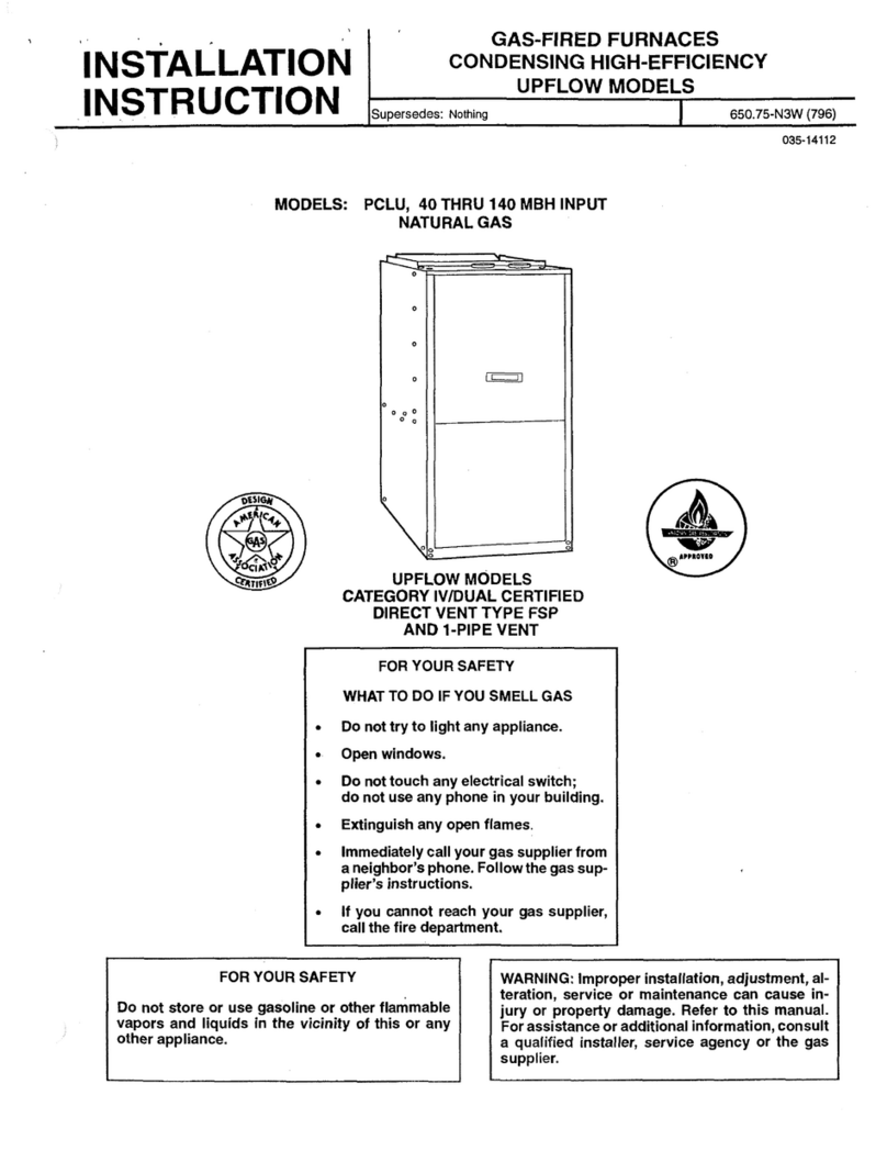
Fraser-Johnston PCLU-LD08N040 User manual

Fraser-Johnston

Fraser-Johnston PCLU-LD08N040 User manual

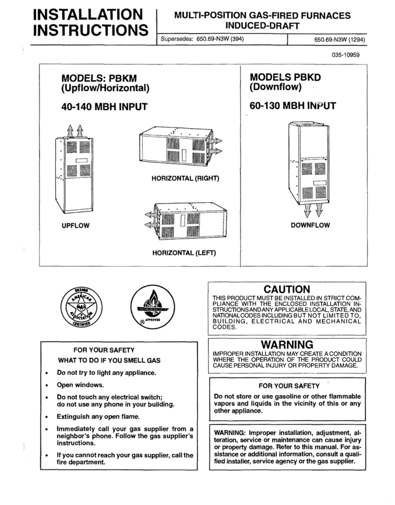
Fraser-Johnston PBKM User manual

Fraser-Johnston

Fraser-Johnston PBKM User manual

Popular Furnace manuals by other brands

Lifebreath AH-ELE-15KW-36-E16 Specification sheet

Lifebreath

Lifebreath AH-ELE-15KW-36-E16 Specification sheet

Napoleon NBM030S2A Installation and operating instructions

Napoleon

Napoleon NBM030S2A Installation and operating instructions

Lennox SL280UHNX Series Unit information

Lennox

Lennox SL280UHNX Series Unit information

UPG 1HA0409 installation instructions

UPG

UPG 1HA0409 installation instructions

Daikin DM80HS0403A manual

Daikin

Daikin DM80HS0403A manual

Johnson Controls TP9C C installation manual

Johnson Controls

Johnson Controls TP9C C installation manual

Rheem Classic Plus 05EAUER User instructions

Rheem

Rheem Classic Plus 05EAUER User instructions

Williamson-Thermoflo PLB-098 LOW-BOY instructions

Williamson-Thermoflo

Williamson-Thermoflo PLB-098 LOW-BOY instructions

Broan Nortron 21ECM10 Installation and user manual

Broan

Broan Nortron 21ECM10 Installation and user manual

Lennox EL280DF SERIES installation instructions

Lennox

Lennox EL280DF SERIES installation instructions

Lennox EL296UHV series User's information manual

Lennox

Lennox EL296UHV series User's information manual

GOLDBRUNN THERM Goldbrunn 1000 user manual

GOLDBRUNN THERM

GOLDBRUNN THERM Goldbrunn 1000 user manual

Whirlpool GAS FURNACE User instructions

Whirlpool

Whirlpool GAS FURNACE User instructions

Vulcan-Hart A-130 Owner's/operator's manual

Vulcan-Hart

Vulcan-Hart A-130 Owner's/operator's manual

Lennox G40DF(X)-24A-045 installation instructions

Lennox

Lennox G40DF(X)-24A-045 installation instructions

Payne C Series Installation, Start-up, Operating, Service and Maintenance Instructions

Payne

Payne C Series Installation, Start-up, Operating, Service and Maintenance Instructions

Lennox GSR14 Installation

Lennox

Lennox GSR14 Installation

Truma Combi eco operating instructions

Truma

Truma Combi eco operating instructions

manuals.online logo
manuals.online logoBrands
  • About & Mission
  • Contact us
  • Privacy Policy
  • Terms and Conditions

Copyright 2025 Manuals.Online. All Rights Reserved.