FSN WUH4000 User manual

Wireless Imaging System
Instructions for Use
Model: WUH4000
Part Numbers: FHD-1TX-1RX
FHD-1TX-2RX
WUH4000
WUH4000-D
Model: WUH4060
Before connecting, operating or adjusting this product, please
read this instruction booklet carefully and completely.
English

28/2021
eIFU
indicator
Table of Contents
Product Description / Intended Use WUH4000 . . . . . . . . . . . 3
Product Description / Intended Use WUH4060 . . . . . . . . . . . 4
Symbol Denitions . . . . . . . . . . . . . . . . . . . . . . . . . . . . . 5
Indications for Use, Contraindications . . . . . . . . . . . . . . . . . 6
Warnings, Precautions . . . . . . . . . . . . . . . . . . . . . . . . . . 7-9
FCC Information . . . . . . . . . . . . . . . . . . . . . . . . . . . . 10-15
WUH4000
Maintenance of Quality Service . . . . . . . . . . . . . . . . . . 16, 17
Package Contents. . . . . . . . . . . . . . . . . . . . . . . . . . . 18, 19
Installation . . . . . . . . . . . . . . . . . . . . . . . . . . . . . . . 20, 21
Panel Interface. . . . . . . . . . . . . . . . . . . . . . . . . . . . . . . 22
Directions for Use . . . . . . . . . . . . . . . . . . . . . . . . . . . 23-25
General Specication . . . . . . . . . . . . . . . . . . . . . . . . 26, 27
Video Resolution Timing . . . . . . . . . . . . . . . . . . . . . . . . 28
Appendix . . . . . . . . . . . . . . . . . . . . . . . . . . . . . . . . 29, 30
WUH4060
Maintenance of Quality Service . . . . . . . . . . . . . . . . . . 31, 32
Package Contents. . . . . . . . . . . . . . . . . . . . . . . . . . . . . 33
Installation . . . . . . . . . . . . . . . . . . . . . . . . . . . . . . . 34, 35
Panel Interface. . . . . . . . . . . . . . . . . . . . . . . . . . . . . . . 36
Directions for Use . . . . . . . . . . . . . . . . . . . . . . . . . . . 37, 38
General Specication . . . . . . . . . . . . . . . . . . . . . . . . 40, 41
Video Resolution Timing . . . . . . . . . . . . . . . . . . . . . . . . 42
The specications and information in this document are subject to change without notice.
Instructions for Use for this product are also available in electronic form (eIFU). Choose
from several languages. Use Adobe Acrobat software to view eIFUs. Access the eIFUs
online at: fsnmed.com/support/eifu/

3
8/2021
WUH4000 Wireless Imaging System
Carefully read all instructions prior to use. Observe all contraindications, warnings and
precautions noted in these directions. Failure to do so may result in patient complications.
Device Description
The 60Ghz WUH4000 transmitter wirelessly transmits high quality audio and video to a paired
WUH4000 receiver in a typical operating room. The transmitter is designed to be connected to a
video source (such as an endoscopic camera) with the receiver connected to a video monitor.
Two WUH4000 transmitter/receiver systems operating at dierent frequencies within the 60Ghz
band can be used simultaneously within the same room.
The WUH4000 is designed to be unaected by cell phones, RFID, wireless 802.11 b/g/n. The
60Ghz operating frequency cannot pass through walls and will work within a 10m radius. 256-bit
AES encryption ensures that no other devices can speak with the WUH4000.
The WUH4000 transmitter dimensions are:
75.8 mm (2.98 in.) high x 140 mm (5.51 in.) wide x 98.25 mm (3.87 in.) deep.
Weight is approximately .57 kg (1.25 lbs).
The WUH4000 receiver dimensions are:
75.8 mm (2.98 in.) high x 55 mm (2.17 in.) wide x 98.25 mm (3.87 in.) deep.
Weight is approximately .23 kg (.5 lbs).
Both components are mains powered (100 – 240 V).
The WUH4000 wireless device is a non-sterile reusable device not intended for use in the sterile eld.
Caution: Federal (U.S.A.) law restricts this device to sale by or on the order of a physician.
Part Number Transmitters Receivers Designed for FHD Designed for 4K
FHD-1TX-1RX 1 1 •
FHD-1TX-2RX 1 2 •
WUH4000 1 1 •
WUH4000-D 1 2 •
AV Source
Transmitter (TX) Receiver (RX) Destination
Product Description / Intended Use

48/2021
WUH4060 Wireless Imaging System
Carefully read all instructions prior to use. Observe all contraindications, warnings and
precautions noted in these directions. Failure to do so may result in patient complications.
Device Description
The 5Ghz WUH4060 transmitter wirelessly transmits high quality audio and video to a paired
WUH4060 receiver in a typical operating room. The transmitter is designed to be connected to a
video source (such as an endoscopic camera) with the receiver connected to a video monitor.
Up to six WUH4060 transmitter/receiver pairs can be used simultaneously.
The WUH4060 is designed to avoid conicts with other wireless devices. The system is designed
to link within the same room, and will work on the same oor within a 30 meter radius. 256-bit
AES encryption ensures that no other devices can speak with the WUH4060.
The WUH4060 transmitter dimensions are:
132 mm (5.20 in.) high x 91 mm (3.58 in.) wide x 27 mm (1.06 in.) deep.
Weight is approximately 360g (.79 lbs).
The WUH4060 receiver dimensions are:
112 mm (4.41 in.) high x 139 mm (5.47 in.) wide x 27 mm (1.06 in.) deep.
Weight is approximately 434g (.96 lbs).
Both components are mains powered (100 – 240 V).
The WUH4060 wireless device is a non-sterile reusable device not intended for use in the sterile eld.
Caution: Federal (U.S.A.) law restricts this device to sale by or on the order of a physician.
Product Description / Intended Use
AV Source Transmitter (TX) Receiver (RX) Destination
Wireless
Connection

5
8/2021
eIFU
indicator
Symbol Denitions
The following symbols appear on the product, its labeling, or the product packing. Each symbol
carries a special denition, as dened below:
Do not disassemble Power adapter Consult accompanying
documents
Non-ionizing electro-
magnetic radiation
Indicates top-bottom
direction Korea Certication
DC Power control
switch Fragile Unique Device Identier
Do not get wet
Voluntary Control Council
for Interference - Japan
Wireless link status
Consult the operating
instructions
Indicates the
manufacturer Catalog Number
Indicates the
manufacturing date
Authorized representative in
the European community
Medical Device
Serial Number Humidity limitation Consult the operating
instructions - electronic
Temperature limitation Atmospheric pressure
limitation Importer Entity
UK Conformity Assessed
Indicates proof of conformity to EU 2017/745 Medical Devices Regulation and applicable
standards.
Medical Equipment is in accordance with ANSI/AAMI ES60601-1: A1:2012, C1:2009/(R)2012 and
A2:2010/(R)2012, CSA CAN/CSA-C22.2 NO. 60601-1:14. Medical electrical equipment Part 1:
General requirements for basic safety and essential performance.
Tested to comply with FCC Class B standard (USA).
Waste electrical and electronic equipment (WEEE Directive 2012/19/EU). This symbol indicates
that the waste of electronic equipment must not be disposed as unsorted municipal waste and
must be collected separately. Please contact the manufacturer or other authorized disposal
company to decommission your equipment.
Note: A printed copy of the manual in English is provided with the product. Users within EU member states,
please contact local distributor for other languages. This applies to EU member states where the product has
been purchased through authorized channels.

68/2021
Indications for Use
The Wireless Imaging System consists of a wireless transmitter and a receiver which delivers
high quality audio and video signals from sources such as endoscopy or laparoscopy camera
systems, or other video sources over radio-frequency to display images during general surgical
procedures. The Wireless Imaging System components are non-sterile reusable devices not
intended for use in the sterile eld.
External equipment intended for connection to signal input, signal output or other connectors,
shall comply with relevant IEC standard (e.g., IEC 60950 for IT equipment and IEC 60601 series
for medical electrical equipment). In addition, all such combination systems shall comply with
the standard IEC 60601-1-1, safety requirements for medical electrical systems. Any person who
forms a system is therefore responsible for the system to comply with the requirements of IEC
60601-1-1. If in doubt, contact a qualied technician or your local representative.
Contraindications
This device is not intended to be used in the vicinity of diathermy equipment.
This device is not intended to be used in the sterile eld.
Intended User
Wireless Systems are intended to be used by trained video system professionals.
Warning
Before connecting the AC power cord to the system, make sure the recommended voltage
designation on the cord corresponds to the available power source.
Never use this system with a damaged power cord. Do not allow anything to rest on the power
cord. Keep the power cord away from areas where it may cause tripping.
Be sure to hold the plug, not the power cord, when disconnecting from an electric socket.
If this system does not operate normally, in particular, if there are any unusual sounds or smells
coming from it unplug it immediately and contact an authorized dealer or service center.
Put this system in a location with low humidity and a minimum amount of dust. Locate it near an
easily accessible AC outlet.

7
8/2021
Warning
Openings in this system’s cabinet are provided for ventilation. To prevent overheating, these
openings should not be blocked or covered. If placed in an enclosed space, be sure to provide
adequate ventilation. Do not attempt to disassemble or modify this product. Only authorized
personnel should perform service. Never insert anything metallic into the cabinet openings and
vents. Doing so may create the danger of electrical shock, and will void the warranty.
Do not touch signal input, signal output or other connectors, and the patient simultaneously. This
system should be installed and operated with a minimum distance of 20 cm between equipment
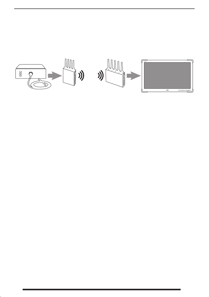
and body. This device is intended to provide video transmission only to a secondary monitor or
display for administrative, educational, or backup purposes; it is not intended to provide primary
video transmission. This system is for indoor use only.
Power
Use only a properly grounded plug and voltage. An improper ground may cause electric
shock or equipment damage.
WARNING: This is a radio-frequency (RF), radiation emitting device that has non-thermal
biological eects for which no safety guidelines have yet been established. Controversy exists
as to whether these eects are harmful to humans. Exposure to RF radiation may be reduced by
limiting your use of this device and keeping away from the head and body.
Repair
Unplug the apparatus from its power source and refer servicing to qualied personnel
under the following conditions:
• If the power cord or plug is damaged or frayed. • If liquid has been spilled into the apparatus.
• If objects have fallen into the apparatus. • If the apparatus has been exposed to rain or moisture.
• If the cabinet has been damaged. • If the apparatus seems to be overheated.
• If the apparatus emits smoke or abnormal odor.
• If the apparatus has been subjected to excessive shock by being dropped.
• If the apparatus fails to operate in accordance with the operating instructions.
Biohazards
To prevent spreading of infections, this device should only be used in environments where
biological decontamination can be successfully performed.
Returned Product
After troubleshooting, if problems persist, disinfect the product and return it to FSN using the
original packaging. Include the accessories that came with the product in the return shipment.
Please enclose a brief explanation of the malfunction.
Contact FSN Medical Technologies for a Return Authorization Number and instructions, prior to
returning the device.

88/2021
Precautions
Always treat the product with care and keep it in a clean and dust-free environment.
Do not expose the product to liquid, moisture, or humidity.
Do not use your product in temperatures above 40°C when unit is operational.
Do not drop or throw the product.
Accessories
Use only accessories specied by the manufacturer, or sold with the apparatus. Do not use die-
rent AC adapters.
Replace damaged equipment. If damage is found call your COMPANY representative. Do not
attempt to operate the system before thoroughly reading these Instructions for Use. For future
reference, keep these documents in a convenient, easily accessible place.
Installation
Do not connect any other wires or accessories which don’t comply with this system to this
system.
An improper wire may cause electric shock or equipment damage. Insert wire connections rmly
so that they do not come loose.
A bad connection may cause a fault. Do not stack and locate close to other equipment.
To prevent re or shock hazards, do not expose this unit to rain or moisture. Do not use this unit’s
polarized plug with an extension cord receptacle or other outlets unless the prongs can be fully
inserted. This device is designed to meet the medical safety requirements for a patient vicinity
device.
This device may not be used in connection with life support equipment.
Others
Please contact this equipment’s supplier when you want to use this system with unknown
equipment. Please power o and pull out the power cord when you want to move this system to
another place.

9
8/2021
Underwriters Laboratories (UL) Classication:
UL safety Compliance:
This system is U.L. Classied WITH RESPECT TO ELECTRIC SHOCK, FIRE AND MECHANICAL
HAZARDS ONLY IN ACCORDANCE WITH UL 60601-1/CAN/CSA C22.2 NO. 601.1
EU Conformity and EMC Compliance:
This system meets the requirements of EN-60601-1 so as to conform to the Medical Device
Directive 93/42/EEC (general safety information).
In addition this system conforms with the essential requirements of Annex 111, Module B, of
the Council Directive 2014/53/EU on Radio Equipment (RED) and the mutual recognition of
their conformity, in relation to the essential requirements of:
Article 3.1 (a) Health and Safety EN 62311 :2008
EN 60950-1 :2006 +A11:2009 + A12:2011 + A1:2010 + A2:2013
Article 3.1(b) EMC Draft EN 301 489-17 v3.2.0, Draft EN 301 489-1 V2.2.0
Article 3.2 Radio Spectrum EN 302 567 V2.1.1
Article 3.3 a-i (Special Features) None are applicable.
This unit uses plug for US: 120V rating 5-15P type only.
This system complies to the above standards only when used with the supplied medical grade
power supply.
Wireless Imaging System Power Supply
WUH4000 Adapter Technology ATM036T-P050
WUH4060 CUI INC SDM36-12-U-P5
Caution: Make sure the power cord is the correct type that is required in your area.
This system has a universal power supply that allows operation in either 100-120V AC or 200-
240V AC voltage areas (no user adjustment is required).
Use the proper power cord with correct attachment plug type. If the power source is 120V AC,
use a Hospital Grade Power Cord with NEMA 5-15 style plug, labeled for 125 volts AC with UL and
C-UL approvals.
If the power source is a 240 V AC supply, use the tandem (T blade) type attachment plug with
ground conductor power cord that meets the respective European country’s safety regulations.
Classication
- Protection against electrical shock: Class I including AC/DC power.
- Applied parts: no applied parts.
- Degree of safety in the presence of ammable anesthetics mixture with air or with oxygen or
with nitrous oxide. Not suitable for use in the presence of a ammable anesthetics mixture
with oxygen or with nitrous oxide.
- Mode of operation: continuous

10 8/2021
FCC Warnings
This equipment has been tested and found to comply with the limits of a Class B digital device,
pursuant to Part 15, Subpart B of the FCC rules. These limits are designed to provide reasona-
ble protection against interference. This system can radiate radio frequency energy and, if not
installed and used in accordance with the instructions, it may interfere with other radio commu-
nications equipment.
There is no guarantee that interference will not occur in a particular installation. If this equipment
is found to cause harmful interference to radio or television reception, the user is encouraged to
try to correct the interference by carrying out one or more of the following measures:
1. Reorient or relocate the receiving antenna.
2. Increase the distance between this system and the subject of interference.
3. Plug this system into an outlet on a dierent electrical circuit than\that to which the subject of
interference is connected.
4. Consult the dealer or an experienced radio/TV technician for help.
NOTICES TO USER :
This device complies with the requirements of FCC CFR 47 Part 15, Subpart B. Operation is sub-
ject to the following two conditions:
1) This device may not cause harmful interference.
2) This device must accept any interference received, including interference that may cause
undesired operation.
However, if used incorrectly, RF interference could hamper its operation or the operation of other
nearby electrical devices. If you suspect either of these conditions, move the conicting equip-
ment farther apart, separate the equipment with an RF barrier, or discontinue use of the system.
This equipment generates or uses radio frequency energy. Changes or modications to this
equipment may cause harmful interference unless the modications are expressly approved in
the instruction manual. The user could lose authority to operate this equipment if an unautho-
rized change or modication is made.
Any serious incident that has occurred in relation to the device should be reported to the manu-
facturer and the competent authority of the Member State in which the user and/or patient is
established. Contact your local FSN Medical Technologies sales representative for information on
changes and new products.

11
8/2021
The FSN wireless imaging system is intended to be used as a pair (transmitter and receiver)
to redundantly display video where needed. The wireless device is a non-sterile, reusable
device, not intended for use in the sterile eld.
FCC Appendix
Manufacturer’s declaration - electromagnetic emission
The WIRELESS IMAGE system is intended for use in the electromagnetic environment specied below. The
customer or the user of the WIRELESS IMAGE system should assure that it is used in such an environment.
Emission test Compliance Electromagnetic environment -guidance
RF Emissions
CISPR 11 Group 1
The WIRELESS IMAGE system uses RF energy only for its internal
function. Therefore, its RF emissions are very low and are not
likely to cause any interference in nearby electronic equipment.
RF Emissions
CISPR 11 Class A The WIRELESS IMAGE system is suitable for use in all establish-
ments other than domestic and those directly connected to
the public low-voltage power supply network that supplies
buildings used for domestic purposes.
Harmonic emissions
IEC 61000-3-2 A
Voltage uctuations
IEC 61000-3-3 Complies
Manufacturer’s declaration - electromagnetic immunity
This WIRELESS IMAGE system is intended for use in the electromagnetic environment specied below. The
customer or the user of the WIRELESS IMAGE system should assure that it is used in such an environment.
Immunity test IEC 60601 Test level Compliance level
Electromagnetic environment-guidance
Electrostatic
discharge(ESD)
IEC61000-4-2
6 kV contact
8 kV air
6 kV contact
8 kV air
Floors should be wood, concrete or cera-
mic tile. If oors are covered with synthetic
material, the relative humidity should be
at least 30%
Electrical fast tran-
sient/burst
IEC 61000-4-4
2 kV for power
supply lines
1 kV for input/out-
put lines
2 kV for power
supply lines
1 kV for input/out-
put lines
Main power quality should be that of a ty-
pical commercial or hospital environment.
Surge
IEC 61000-4-5
1 kV dierential mode
2 kV common mode
1 kV dierential mode
2 kV common mode
Main power quality should be that of a typi-
cal commercial or hospital environment.
Power frequency
(50/60Hz) Magnetic
eld IEC 61000-4-8
3.0 A/m 3.0 A/m
Power frequency magnetic elds should
be at levels characteristic of a typical lo-
cation in a typical commercial or hospital
environment.
Voltage dips, short
Interruptions and
voltage varia-
tions on power
supply input lines
IEC61000-4-11
<5% UT(>95% dip in UT)
for 0.5 cycle
40% UT(60% dip in UT)
for 5 cycle
70% UT(30% dip in UT) for
25 cycle
<5% UT(<95% dip in UT)
for 5 sec.
<5% UT(>95% dip in UT)
for 0.5 cycle
40% UT(60% dip in UT)
for 5 cycle
70% UT(30% dip in UT) for
25 cycle
<5% UT(<95% dip in UT)
for 5 sec.
Main power quality should be that of a ty-
pical commercial or hospital environment.
If the user of WIRELESS IMAGE system re-
quires continued operation during power
mains interruptions, it is recommended
that WIRELESS IMAGE system be powered
from an uninterruptible power supply or
a battery.
Note: UTis the A.C. mains voltage prior to application of the test level.

12 8/2021
This WIRELESS IMAGE system is intended for use in the electromagnetic environment specied below. The
customer or the user of this WIRELESS IMAGE system should assure that it is used in such an environment.
Immunity test IEC 60601 Test
level
Compliance level
Electromagnetic environment-guidance
Conducted RF
IEC 61000-4-6
3 Vrms
150 kHz to 80MHz
3 Vrms
150 kHz to 80MHz
Portable and mobile RF communications
equipment should be used no closer to
any part of the WIRELESS IMAGE system,
including cables, than the recommended
separation distance calculated from the
equation applicable to the frequency of the
transmitter.
Recommended separation distance: d
݀ൌ
͵ǡͷ
ܸଵ൨ξܲ
Radiated RF
IEC 61000-4-3
3 V/m
80.0 MHz to
2.5GHz
3 V/m
80.0 MHz to
2.5GHz
Recommended separation distance
݀ൌ
͵ǡͷ
ܧଵ൨ξܲ80MHz to
800MHz
݀ൌ
ܧଵ൨ξܲ80MHz to
2.5GHz
Where Pis the maximum output power
rating of the transmitter in watts (W) accor-
ding to the transmitter manufacturer and
dis the recommended separation distance
in meters (m). Field strengths from xed
RF transmitters, as determined by an elec-
tromagnetic site survey, (a) Should be less
than the compliance level in each frequency
range (b).
Interference may occur in the vicinity of
equipment marked with the following
symbol:
Note 1) UTis the A.C. mains voltage prior to application of the test level.
Note 2) At 80MHz and 800 MHz, the higher frequency range applies.
Note 3) These guidelines may not apply in all situations. Electromagnetic propagation is aected by ab-
sorption and reection from structures, objects and people.
a. Field strengths from xed transmitters, such as base stations for radio (cellular/cordless) telephones and land mobile radios,
amateur radio, AM and FM radio broadcast andTV broadcast cannot be predicted theoretically with accuracy. To assess
the electromagnetic environment due to xed RF transmitters, an electromagnetic site survey should be considered. If the
measured eld strength in the location in which the EUT is used exceeds the applicable RF compliance level above, the EUT
should be observed to verify normal operation. If abnormal performance is observed, additional measures may be necessary,
such as re orienting or relocating the EUT.
b. Over the frequency range 150 kHz to 80 MHz, eld strengths should be less than [V1] V/ m.

13
8/2021
Recommended separation distances between portable and mobile RF communications equipment and the
WIRELESS IMAGE system.
The WIRELESS IMAGE system is intended for use in an electromagnetic environment in which radiated RF
disturbances are controlled. The user of the WIRELESS IMAGE system can help prevent electromagnetic
interference by maintaining a minimum distance between portable and mobile RF communications equip-
ment (transmitters) and the WIRELESS IMAGE system as recommended below, according to the maximum
output power of the communications equipment.
Rated maximum output
power [W] of transmitter
Separation distance according to frequency of transmitter[m]
150kHz to 80MHz 80MHz to 800MHz 800MHz to 2.5GHz
0.01 0.12 0.12 0.23
0.1 0.37 0.37 0.74
1 1.17 1.17 2.33
10 3.70 3.70 7.37
100 11.70 11.70 23.30
For transmitters rated at a maximum output power not listed above, the recommended separation dis-
tance (d) in meters (m) can be estimated using the equation applicable to the frequency of the transmitter,
where P is the maximum output power rating of the transmitter in watts (W) according to the transmitter
manufacturer.
Note 1) At 80 MHz and 800 MHz, the separation distance for the higher frequency range applies.
Note 2) These guidelines may not apply in all situations. Electromagnetic propagation is aected by ab-
sorption and reection from structures, objects and people.

14 8/2021
Guidance and manufacturer’s declaration - electromagnetic immunity
This WIRELESS IMAGE system is intended for use in the electromagnetic environment specied below. The
customer or the user of this WIRELESS IMAGE system should assure that it is used in such an environment.
Immunity test IEC 60601 Test level Compliance level
Electromagnetic environment-guidance
Conducted RF
IEC 61000-4-6
3 Vrms
150 kHz to 80MHz
3 Vrms
150 kHz to 80MHz
WIRELESS IMAGE system must be used
only in a shielded location with a mi-
nimum RF shielding eectiveness and,
for each cable that enters the shielded
location with a minimum RF shielding
eectiveness.
Radiated RF
IEC 61000-4-3
3 V/m
80.0 MHz to
2.5GHz
3 V/m
80.0 MHz to
2.5GHz
Field strengths outside the shielded
location from xed RF transmitters, as
determined by an electromagnetic site
survey, should be less than 3V/m (a).
Interference may occur in the vicinity of
equipment marked with the following
symbol:
Note 1) These guidelines may not apply in all situations. Electromagnetic propagation is aected by ab-
sorption and reection from structures, objects and people.
Note 2) It is essential that the actual shielding eectiveness and lter attenuation of the shielded location
be veried to assure that they meet the minimum specication.
Field strengths from xed transmitters, such as base stations for radio (cellular/cordless) telephones and
land mobile radios, amateur radio, AM and FM radio broadcast and TV broadcast cannot be predicted
theoretically with accuracy. To assess the electromagnetic environment due to xed RF transmitters, an
electromagnetic site survey should be considered. If the measured eld strength outside the shielded
location in which the EUT is used exceeds 3V/m, the EUT should be observed to verify normal operation. If
abnormal performance is observed, additional measures may be necessary, such as relocating the EUT or
using a shielded location with a higher RF shielding eectiveness and lter attenuation.

15
8/2021
FCC Caution:
Any changes or modications not expressly approved by the party responsible for compliance
could void the user’s authority to operate this equipment.
FCC Radiation Exposure Statement:
This equipment complies with FCC radiation exposure limits set forth for an uncontrolled
environment. This equipment should be installed and operated with minimum distance 20cm
between the radiator & your body.
IC Class B Statement (Canada)
This Class B digital apparatus complies with Canadian ICES-003 and RSS-210. Cet appareil nu-
mérique de la classe B conforme á la norme NMB-003 et RSS-210 du Canada. Operation is subject
to the following two conditions: (1) this device may not cause interference, and (2) this device
must accept any interference, including interference that may cause undesired operation of the
device.
EU Declaration of Conformity (DoC)
Hereby declares that this device is in compliance with the essential requirements and other
relevant provisions of the Medical Device Regulation (EU) 2017/745and the EU RoHS Directive
2011/65/EU+2015/863/EU. This device is determined to be Class I according to Rule 1 of Annex
VIII of MDR 2017/745.

16 8/2021
10 meters 33 feet
5 meters
16.4 feet
5 meters
16.4 feet
RxTx
WUH4000 is designed to maintain an adequate Quality of Service during its use in a hospital
operating room environment.
Design Characteristics: Interference from other WUH4000 Devices
The WUH4000 uses Beam Forming Non Line Of Sight technology (BFNLOS). As a result, WUH4000
links in one location will NOT transmit through solid walls or doors with WUH4000 devices in
another location. Using BFNLOS, the WUH4000 has been tested to work consistently within a
10m radius of the transmitter.
Using its unique mating procedure, the WUH4000 transmitter is constructed to work only
with the WUH4000 authenticated receivers. It’s HDCP protocol not only blocks hackers from
high jacking or altering a signal, but it also stops other WUH4000 Transmitters/Receivers from
breaking into the communication between linked Transmitter and Receiver. If more than one
WUH4000 wireless systems are operating simultaneously in a single room, each will be on a
separate frequency within the 60GHz band and can support up to a maximum of 4 receivers
within that room.
As a result of these design considerations, it is not possible for one WUH4000 System to interfere
with another WUH4000 System.
Maintenance of Quality of Service WUH4000

17
8/2021
Design Considerations: Interference from other Devices
The WUH4000 is validated to be compatible with other devices that are commonly found in an
operating environment, in accordance with IEC 60601-1-2. In that testing, the WUH4000 needed
to maintain the following Essential Performance to ensure that its performance was adequate
when the System was exposed to other electronic equipment. WUH4000 Essential Performance
requires that a viewable image shown on a secondary monitor via a WUH4000 pair be consistent
with the following criteria:
1. A viewable image is generated
2. There is no ickering of the image
3. There is no clipping of any edges
4. Brightness and detail of image remains consistent across the whole image
These criteria ensure that no resultant video degradation could be judged to be clinically signi-
cant.
For best results, verify the following:
The TX and RX are facing each other.
The TX and RX are no more than 10 meters apart.
The TX and RX are between 6-10 ft above the oor.
The TX and RX are not in a conned location.
Noninterference Distances
The following minimum distances have been tested to demonstrate noninterference between
the listed devices and the WUH4000. If the WUH4000 is thought to be causing or receiving inter-
ference with the following devices, then move the devices away from each other, maintaining at
least the following separations:
Equipment Transmitter Receiver
Electrocautery > 610 mm, (24 inches) > 305 mm, (12 inches)
RFID > 10 mm, (.39 inches) > 10 mm, (.39 inches)
2.4GHz Wireless > 152 mm, (6 inches) > 152 mm, (6 inches)
5.8 GHz Wireless > 152 mm, (6 inches) > 152 mm, (6 inches)
Cell Phone > 10 mm, (.39 inches) > 10 mm, (.39 inches)
Bluetooth > 10 mm, (.39 inches) > 10 mm, (.39 inches)
The WUH4000 is not intended to be used in the vicinity of diathermy equipment. If diather-
my equipment is operated around the WUH4000 and interference is suspected, turn o the
WUH4000 Transmitter and Receiver.
Maintenance of Quality of Service WUH4000

18 8/2021
67
4
5
13
2
8
9
10
11
12
Package Contents Part No.: FHD-1TX-1RX (Model: WUH4000)
Item Description Quantity
1 Wireless transmitter (TX unit) 1
2 Wireless receiver (RX unit) 1
3 Partition 1
4 Power adapter 2
5 Power cord 2
6 User guide 1
7 Monitor VESA mount bracket 2
8 HDMI 1.4 to HDMI 1.4 cable, 1.5 feet 1
9 HDMI to DVI cable, 1.5 meter* 2
10 Video splitter/adapter (optional, if required) 1
11 Micro USB cable for power from wireless receiver to splitter/adapter, 1.5 feet 1
12 Mounting screw packet 1
* Option is available for one of the two cables to be 3 meter.
Verify that all components for the respective package are accounted for. Inspect each component
to verify that none have been tampered with in any way.

19
8/2021
8
67
9
4
5
13
2
Item Description Quantity
1 Wireless transmitter (TX unit) 1
2 Wireless receiver (RX unit) 1
3 Partition 1
4 Power adaptor 2
5 Power cord 2
6 User guide 1
7 Monitor VESA mount bracket 2
8 HDMI 2.0 to HDMI 2.0 cable, 2 meter 2
9 Mounting screw packet 1
Verify that all components for the respective package are accounted for. Inspect each component
to verify that none have been tampered with in any way.
Package Contents Part No.: WUH4000 (Model: WUH4000)

20 8/2021
A
B
C
D
10 m (33 ft.) max.
1.8-3 m
(6-10 ft.)
Plan the Installation WUH4000
Identify the signal source for wireless transmission (example A).
Determine the location of the WUH4000 transmitter (TX) unit (example B).
Find a suitable power source for the transmitter.
Identify the destination to receive the wireless signal (example C).
Determine the location of the WUH4000 receiver (RX) unit (example D).
Find a suitable power source for the receiver.
The transmitter and receiver units can stand alone on a at surface, or use a bracket to mount
onto other objects such as a display monitor. It is recommended to verify that the wireless system
is operating properly before mounting the TX or RX units permanently.
For best installation results:
• The TX and RX should face each other.
• The TX and RX should be no more than 10 meters (33 ft.) apart.
• The TX and RX should be between 1.8-3 meters (6-10 ft.) above the oor.
• The TX and RX should not be in a conned location.
This manual suits for next models
4
Table of contents