FUJIDENZO IJWA-1050T User manual

Service Manual
Washing machine
Note:
Before serving the unit,please read this at first,
Always contact with your service center if meet problem.

SpecificationSpecification
1
Specification.................................................1
The circuit diagram/Parts name.......................2
Control panel instruction.................................3
The points for installation, adjustment and
disassembly..................................................4-7
Fault diagnosis..............................................8-15
Contents
Dimensions
W600mm D622mm H970mm
Weight
Rated voltage and frequency
Model
Water level/water volume about
Inlet pressure
220V~ 60Hz
0.03MPa~0.85MPa
IJWA-1050T
Rated input power
About 42kg
10.5kg (dry laundries weight)
Rated capacity of wash and spin
10/78L 9/74L 8/70L 7/65L
6/60L 5/56L 4/52L 3/48L
2/44L 1/40L
Wash 360W spin 175W

The circuit diagramThe circuit diagram
Parts nameParts name
2
Power cord
Fixing foot(2pcs)
Back cover
Foot wheel(2pcs)
Feed valve
Earthing wire
Top lid
Top frame
Detergent box
Lint filter1
Control panel
Inner tub
Pulsator
Body
Base
Adjustable foot
Drainpipe connector
balancing
apparatus
Lint filter

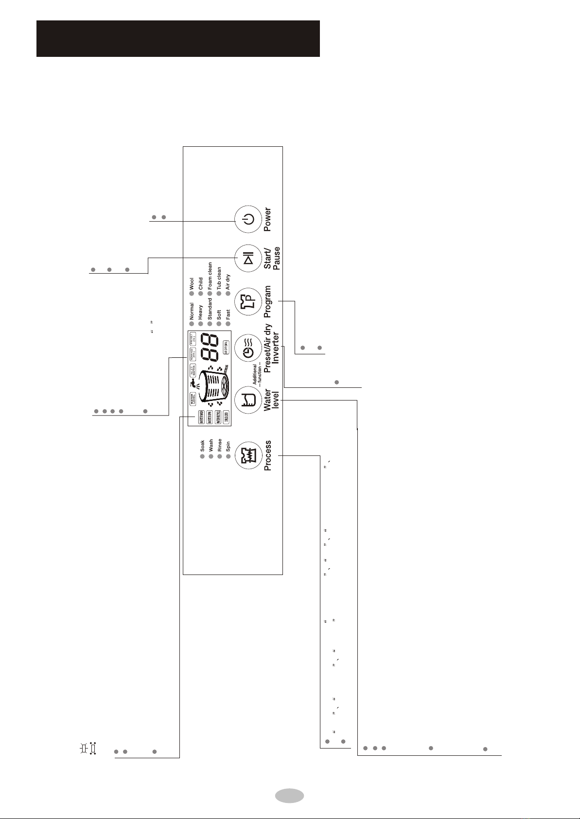
Control panel instructionControl panel instruction
3
Mode and meaning of the indicator light
on: indicate the selected mode
flashing: indicate the program is running
Additional functions
Press this button to select the water level manually
Press this button together with the PRESET/DRY AIR/INVERTER to activate the
WATER RECYCLE. INVERTER WASH and INVERTER SPIN options. Please see page
12 instructions on how to adjust them.
After as wash program has been started, press this button together with
PRESET/DRY AIR/INVERTER to activate the CHILD LOCK function
Press this button to select one cycle from wash-rinse-spin spin soak-wash-rinse -spin
wash wash-risne rinse-spin .
The default process setting is "wash-rinse-spin". To activate the, SOAK process, press and hold this button
NORMAL and HEAVY wash programs have automatic water level system.
STANDARD and other wash programs have manual water level system.
For the manual water level selection, see guide below to choose the appropriate water level
according to the wash load:
Level 1-2 is for low water level
Level 3-6 is for medium water level
Level 7-10 is for high water level
In an on-going wash or rinse cycle, if additional water is needed, user may do any of the following:
1. Press the WATER LEVEL button, this will add water into the tub. Pressing it again
will stop the additional water from flowing.
2. Press START/PAUSE and then press the WATER LEVEL button to select a higher water level.
Then press the START/PAUSE button again for the washing machine to start adding water,
once the new water level is reached, the wash program will automatically resume.
Automatically adds water: if during SOAK, WASH, or RINSE process, the water level has lessened
due to overflows, the machine will automatically correct the water level.
Press this button after selecting the program,
process and water level.
Can select one program from NORMAL,HEAVY,STANDARD,SOFT,
FAST, WOOL,CHILD,FOAM CLEAN,TUB CLEAN and AIR DRY
The default program is NORMAL.
Used to turn the machine ON/OFF
WASH program time is shown in MINUTES
When machine encounters an abnormal
condition, indicator will show the diagnostic
code.
AIR DRY time is shown in MINUTES
Right after the washing machine is turned
on, the indicator shows -- , this means
that its running in AUTO mode..
DELAY time is shown in HOURS
Press this button to temporarily stop the washer's
operation.
Press this button to resume the washer's operation.
Used to cancel a washing program
Press this button to customize the settings for the DELAY, AIR DRY and INVERTER
options. Please refer to page 12 for instructions on how to adjust the settings for
these options

The points for installation, adjustment and disassemblyThe points for installation, adjustment and disassembly
Loosen Fasten
Adjustable
nut
Adjustable
foot
High Low
Please install and adjust the machine according to the requirements of the manual.
It is very important to your safety and correct operation.
Unpacking
Unpack the carton and take out the bottom panel.
Open the top lid of washing machine and take out all of the accessories.
Remove all wrappers, including the polystyrene base.
You are advised to keep all the packaging for reuse in case the machine is to be
transported again.
Positioning
The distance between the washing machine and the wall should be more than 50mm, and the
maximum allowed angle of the shank base of the machine is 1 .The slanting or rough ground may
cause operating stopped or unstable, please adjust it with the following methods:
Horizontal checking
observe the water bubble in balancing apparatus
is in red circle or not. In red circle, it is horizontal
Adjust the adjustable foot
1 Lift up the adjustable foot gently, loose the adjustable nut
and twist the adjustable foot.
2 Fasten the nut after adjustment.
3 set the machine flat, and observe again. If the water bubble
is not in red circle, repeat the above procedure , till the water
bubble is in red circle
1
Installing the bottom cover
Let the back of washing machine incline forward make
the side of bottom cover with sticker description back to
washing machine insert to the bottom of washing machine
along the direction of arrow.
Remove two fixing clamp by scissors insert to the
accordingly holes red lines indicating gently pull
fixing clamp should not be pulled out make the
bottom cover fixed on the base.
Fixing clamp
Scissors
Bottom cover
The base
4

If the additional drainpipe is too long,
cut some at A or B point.
Water drainage
The drainpipe should drain smoothly
1.The height of the drainpipe should be less
than 10cm, otherwise the drainage will not be
smooth and need a long time to drain, the machine
may stop during working.
2.Do not step on or press the drainpipe.
4. Purchase a proper hose if you need additional
drainpipe. Its diameter should not less than
30mm and length should not exceed 1.5m.
A B
3.Cut the drainpipe if it is too long. Cut the front end of the
drainpipe slantingly to make drainage smoothly.
How to change the direction of the drainpipe
1.Take off the drainpipe and drainpipe clip from
drainpipe connector, put some soft mat on the floor,
make washing machine front side adown and gently
put down the washing machine front side on the mat,
demount the screws on the back cover with screwdriver
and take out the back cover. Demount one screw that
fixed the drainpipe connector(on right of the washing
machine), loosen the drainpipe connector.
3. With proper force to take down drainpipe gate stopper
on left side of the washing machine. The drainpipe gate
stopper is fixed on washing machine base with two
clips, please see the fixing type from the place of
opening back cover.
2. Extrude the drainpipe with proper force
and take out drainpipe hoop(on right of the
washing machine),make the the inner
drianpipe loosen.
4. Pull the inner drainpipe to another side ,
please do not make the inner drainpipe
distortion; as per foregoing description,
fix inner drainpipe with drainpipe hoop,
with one screw fix drainpipe connector,
install the drainpipe gate stopper to
another side, make washing machine
standing gently,fix back cover with screw
and install the drainpipe and drainpipe
clip into the drainpipe connector.
Install drainpipe
Set drainpipe clip into the drainpipe to 2-3cm (from the drainpipe end that without pothook
to set), then install the drainpipe into the right drianpipe connector and fix the drainpipe
and drianpipe connector with the clip,after that put up the drainpipe clip on the cabinet.
Drainpipe hoop
Drainpipe gate stopper
Drainpipe connector
Drainpipe
Drainpipe clip
(Section sketch map for washing machine right side)
Section sketch may inside washing machine
Section sketch map for washing machine left side
5
The points for installation, adjustment and disassemblyThe points for installation, adjustment and disassembly

>10mm
Lock lever
Inlet hose
Inlet hose connector
Slider
Screwdriver
Bolt
Bushing
Before twisting,about 4mm
After twisting,less 2mm
Nut
Illustration 1 Illustration 2 Illustration3
Illustration 6
Illustration 5
Illustration 4
Tap selection
Suitable tap Not suitable tap
The front end should be longer than 10mm The tap exit end face
should be flat and smooth, if not file it to avoid leakage
Connect the inlet hose connector with the tap
1 Press the lower end of the lock lever and push down the slider, take off the inlet hose
connector from the inlet hose, see illustration 1.
2 Loosen the four bolts on the inlet hose connector till the tap can be accessed, then
set the inlet hose connector in the tap, see illustration 2.(if the tap caliber is too larger and
could not set the inlet hose end, unscrew the four bolts and take out the bushing, tap exit
end must flat, otherwise it will leak, see illustration 3)
3 Fasten the four bolts in the inlet hose connector evenly, see illustration 4.
4 Twist the fastening nut as the illustration ,see illustration 5.
Remark before twisting the nut, the threading is about 4mm above the upper surface of the nut, after twisting,
the threading is less than 2mm above the upper surface of the nut, see illustration 6.
The points for installation, adjustment and disassemblyThe points for installation, adjustment and disassembly
6

Connect the inlet hose connector with the inlet hose
Check the connection between inlet hose
connector and the tap
Inlet valve connector
Inlet hose nut
Water absorption cushion
Lock lever
Inlet hose connector
Slider
1. Push down the slider, insert the inlet hose into the connector
2. Hang the lock lever to the inlet hose connector and release
the slider till a click sound is heard.
1. Swing the inlet hose gently to confirm if it is fastened.
2. After installation, open the tap and check if it leaks.
3. Do not bend the inlet hose with overstrain.
4. Before each usage, check the connection between
inlet hose connector and the tap, and the installation
of inlet hose. Make sure they are firmly fitted to prevent
dropping from improper installation position.
Slider
Lock lever
Connect the inlet hose with the washing machine
1. Do not take off the water absorption cushion. Please
check if the cushion is dropped or damaged before
each usage. If it is, contact the seller immediately.
2. Put the inlet hose nut on the inlet valve connector.
3. Fasten the inlet hose nut and swing it gently to make
sue if it is suitable.
1. Close the tap.
2. Press the locking lever, push down the slider, and pull of the
inlet hose. If the machine is used frequently, the connector
of the inlet hose can be kept on the tap to prevent damaging
the fixing screw.
Dismantle the inlet hose
Cautions:When install the washing machine, please use the new hose assy along with the washing
machine, old hose assy can not reuse.
The points for installation, adjustment and disassemblyThe points for installation, adjustment and disassembly
7

Insert the plug tightly
Check the socket or change to another socket
Press power switch
Check power supply
Install the inlet hose again
Tighten the connector of the machine
Restart when water supply is resumed
Open the tap
Clean the filter according to before clean inlet gate
The machine is adjusting automatically
Close the top lid
Close the top lid
Normal
Normal
Put down the drainpipe
Straighten or clean the drainpipe
Settlement
It does not drain
It does not inlet
Spin stops and begins to inlet
during spin program
Press the program button to
select SPIN, but It does not spin
The spin is intermittent when spin
starts
First time to use, some water flows
from the drainpipe
No water supply
Tap is not open
Inlet hose gets blocked
Laundries is too much or too little or the
Machine is not place stably
Control panel has no any display
Plug is not inserted tightly
No electricity in the socket
Power switch is not turned on
Power supply is cut off
Inlet hose leaks
Inlet hose connector(connecting with the tap)is not fixed tightly
Inlet hose and washing machine connector is loose
Drainpipe is not put down
Drainpipe is bended or get blocked
The remaining water when the factory make test
Do not close the top lid when drain is finished
Open up the top lid when start drain
Balance the laundries to reach to the best spin effect
Phenomena Possible reason
Fault Diagnosis(I)
the following cases,sometimes it is not a malfunction,please confirm before
call the after-service
Fault diagnosisFault diagnosis
some faults can be identified by the machine, and give an alarm automatically,
prompt the user to deal with,see the table below
8
E1
E3
E2
F1
E4
E0
DISPLAY DESCRIPTION SOLUTION
The top lid is opened after the
Delay Wash feature has
been started
Close the top lid and clear thealarm
When draining takes
longer than 5 minutes.
Open the top lid and then close it to clear
the alarm. If diagnostic code still appears,
call for a service technician to check for
clogs on the drain valve.
The top lid was opened
during the spin cycle
Close the top lid toclear the alarm.
An unbalance from the
load is detected during
the spin cycle
Open the top lid.Arrange the load and
equally distribute it within the wash tub.
Then, lose the top lid toclear the alarm.
When the machine takes
more than 20 minutes to
reach the correct water level
Check if the water supply has enough
pressure. Open the top lid and then
close it to clear thealarm.
The water level sensor cannot
correctly detect if there is
water inside the tub.
Turn of the washing machine and then call
for a service technician.
E5
(flashes as the same time
as the Child-Lock icon)
The top lid isopened after
the Child-Lock feature
has been activated
Close the top lid toclear the alarm.
F2
Inverter board
communication failure
Turn of the washing machine and then call
for a service technician.

Fault diagnosisFault diagnosis
Fault Diagnosis(II)
If you change the program controller without examining the condition of other parts carefully whenrepair, it may
lead to damaging the program controller furtherly. Therefore, pleaseassure that other relevent parts work well
1. No action(The indicator light is off)
Change the
program controller
Yes
Infinity
Infinity
change power cord
Resistance
zero
Resistance
zero
check if other electric
partshave any problems
Yes
change the fuze
change the
program controller
check if other electric
parts have any problems
Measure the resistance between inner
terminal of wiring group blue two core
and plug zero terminal
No
Measure the resistance between inner
terminal of wiring group brown two core
and plug zero terminal
Infinity
check the fuze burn out
check if the fuze and both ends of
wire contact well
No
connect the fuze and both ends
of wire
Make sure no power failure, power plug
connect tightly and the switch is on
Measure the program controller,
power input voltage between contactors
( blue double core terminals)
No
Measure the resistance between
the terminal on the blue wire which
is dual-core plastic part and the
blue wire of the wire assembly Change the
wire assembly
Yes
Yes
2.No rotate when dehydrate
wash and drain properly
check the on/off press on cap
switch and biase witch
No on/off change safety switch
No
Yes
change drain
retraction
Make sure the clutch pawl is in place
change clutch check whether drain
retraction works well
Unplug
Resistance
zero
9

3.No water
make sure the action
sound of inlet valve
pemove the foreign matter of inlet
valve's filter or increase to 0.03mpa
to 0.85 mpa and strat again
measure the voltage
across of inlet valve
measure program controller
and input voltage across
change program controller
change inlet valve
change wiring group
switch on, press
start/stop bottom
make sure if inlet
valve works well
No
Yes
Yes
No
Yes
No
Yes
No
No
Yes
Yes
No
No
Yes
Yes
No
4.Loud noise when wash
pulsator grinds the
inner tube bottom
whether belt puller loosens
whether belt is too loose or tight
whether the internal gear of
reducer meshes wll
whether the motor is
installed firmly
noise in motor change motor
fasten motor
change reducer
adjust belt
faster belt pulley
adjust the gap of pulsator
and inner tube
Fault diagnosisFault diagnosis
10

start exclusive water washing
process and wash without water
No
Work
No
Yes
No
5.Don't rotate
check the action of motor
Yes
No
No
Yes
make sure whether motor
and capacitor work well
change program controller
measure program controller
input voltage across
measure the voltage across of motor
whether motor
pritection work
whether capacitor open
circuit or short circuit
chang mator
change
wiring group
Yes
find the cuse
change the
capacitor
Carefully inspect
the drive system
Whether it is normal or not that
the bearing part locks the clutch
change drain
retraction
set rinse or rined and start
No
Yes
Yes
6.No draining
make sure whether
the retractor work
check drain system such as
drain valve and drain hose
measure voltage cross
drain retraction
change wire assy
No
Yes
measure program controller
and input voltage across
No
change program controller make sure whether
drainage traction works well
Fault diagnosisFault diagnosis
11

No
7.Non-stop
No
No
No
No
don't plug in and turn on the tap
inlet valve waters change inlet valve
Yes
Yes
Yes
Yes
Yes
contact impulse tube and blow air
into water level sensor then check
whether it blocks
remove matter and ect
use glue when install impulse tube
paste sealant when install chamber cap
air leakage please
overhaul gas system
change wire assy
check whether inletvalve works well
change program controller
plug in and don't press
start/stop bottom
inlet valve waters
check the wire connects PCB
and water level sensor well
Start with less or low water level
and check the gas chambel has water
check the gas system is blocked
change water level sensor
Fault diagnosisFault diagnosis
12

8.Loud noise when drain
No
No
Yes
Yes
Yes
noise in motor
whether the motor is installed firmly
No
Yes
Yes
No
Yes
Yes
No
No
No
hanger rod seat lock oil and refuels it
whether impluse tube or wiring group
whether the external bung of gimbals
or inner tube fasten in place
whether fuselage and
airframe resonates
whether ratchet and
pawl separate well
whether bearing of reducer
works well
fasten impulse
tube and wiring group
adjust the gap of girnbals
and external barrel or refasten
inner tube
adjust and balance the airfarme
adjust the angle and distance
of retractor and pawl
change retractor
fasten motor
change motor
Fault diagnosisFault diagnosis
13

Yes
Yes
Yes
Yes
Yes
No
No
Yes
Yes
No
No
No
No
No
9.Dad waterfall
channel deform change conduit
channel is blocked by threads
pulsator lining is worn away
single-rotation time is too long when
normalwashing
belt and pulley wear heavily
loose belt
low voltage
soft current normal wash gentle may
not have waterful
start till power
voltage recover
change belt and pulley
change belt or pulley
change PCB
change pulsator
remove threads
Fault diagnosisFault diagnosis
14

No
Yes
Yes
10.Drake timeout
No
Yes
No
no-load brake time exceeds 5 seconds
full-load brake time exceeds 12seconds
braking torque of reducer less
than 7N/M change braking torque
adjust and reset spring
when check drain make sure paw;
cam disengage ratchet wheel
if not adjust the brake position
reducer reset spring matterss
the gap between the truss arm of drain
valve and brake arm of reducer
change clutch
Fault diagnosisFault diagnosis
15
Table of contents