Ganz CTR-4024 User manual

TIME LAPSE VCR
Before connecting, operating, or adjusting this
product, please read this instruction booklet
carefully and completely.
MODEL: CTR-4024(B)
OWNER’S MANUAL
WARNING : TO REDUCE THE RISK OF FIRE OR ELECTRIC SHOCK,
DO NOT EXPOSE THIS PRODUCT TO RAIN OR MOISTURE.
If you pour a cold liquid into a glass, water vapor
in the air will condense on the surface of the glass.
This is moisture condensation. Moisture conden-
sation on the head drum, one of the most crucial
parts of the unit, will cause damage to the tape.
When the VCR is exposed to a rapid temperature
change from cold to warm, some condensation
will occur. Under this condition, connect the power
cord to the AC line, press POWER button on and
allow at least two hours for the VCR to dry out.
MOISTURE CONDENSATION
RISK OF ELECTRIC SHOCK
DO NOT OPEN
CAUTION
CAUTION : TO REDUCE THE RISK
OF ELECTRIC SHOCK,
DO NOT REMOVE COVER (OR BACK);
NO USER-SERVICEABLE PARTS INSIDE
REFER SERVICING TO QUALIFIED SERVICE
PERSONNEL.
The serial number is found on the back of this
unit. This number is unique to this unit and not
available to others. You should record requested
information here and retain this guide as a per-
manent record of your purchase.
Model No.
Serial No.
CAUTION : TO PREVENT ELECTRIC SHOCK,
DO NOT USE THIS PLUG WITH AN EXTEN-
SION CORD, RECEPTACLE OR OTHER OUT-
LET UNLESS THE PLUG CAN BE FULLY
INSERTED WITHOUT EXPOSING ANY PARTS
OF THE BLADES.
This lightning flash with arrowhead sym-
bol within an equilateral triangle is intend-
ed to alert the user to the presence of
uninsulated dangerous voltage within the
product’s enclosure that may be of suffi-
cient magnitude to constitute a risk of
electric shock to persons.
The exclamation point within an equilater-
al triangle is intended to alert the user to
the presence of important operating and
maintenance (servicing) instructions in
the literature accompanying the product.
WARNING: Do not install this equipment in a con-
fined space such as a bookcase or similar unit.
CAUTION: The apparatus should not be exposed
to water (dripping or splashing) and no objects
filled with liquids, such as vases, should be placed
on the apparatus.
IMPORTANT COPYRIGHT INFORMATION: Many
television programs and films are copyrighted. In
certain circumstances, copyright law may apply to
private in-home video taping of copyrighted materi-
als.
Warning : This is a class A product . In a domestic enviroment this product
may cause radio interference in which case the user may be
required to take adequate measures.
Plug wiring
This appliance is supplied with BC 1363 approved 13
Amp fused mains plug. When replacing the fuse always
use a 5 Amp BS 1362 approved type.
Never use this plug with the fuse cover omitted. To obtain
a replacement fuse cover contact your
supplying dealer or VISTA LTD.
If the mains sockets in your home differ, or are not suitable
for the type of plug supplied then the plug should be
removed and a suitable type fitted.
If the mains plug becomes severed from the mains lead it
must be destroyed. A mains plug with bared wires is
hazardous if engaged in a mains output line socket.
If a 13 Amp BS 1363 plug is not suitable or any other
type of plug used, then this appliance must be protected
by a 5 Amp fuse.
Should you need to change the plug
The wires in this mains lead are coloured in accordance
with the following codes
BLUE ~ Neutral
BROWN ~ Live
GREEN & YELLOW ~ No connection to be made
As the colours of the wires in the mains lead of this
appliance may not correspond with the coloured markings
identifying the terminals in your plug proceed as follows:
The wire which is coloured BLUE must be connected
to the terminal which is marked with the letter N or
coloured BLACK.
The wire which is coloured BROWN must be connected
to the terminal which is marked with the letter L or
coloured RED.
DO NOT connect the wire which is coloured GREEN & YELLOW or
GREEN.

3
CONTENTSFEATURES
INTRODUCTION
Features/Contents . . . . . . . . . . . . . . . . . . . . . . . . . . . .3
PREPARATION
Control Names and Locations . . . . . . . . . . . . . . . . .4-6
Installation/VCR to Monitor and CCD Camera
Connection . . . . . . . . . . . . . . . . . . . . . . . . . . . . . . . . .7
Mutiplexer Connections . . . . . . . . . . . . . . . . . . . . . . . .8
Matrix Switcher Connections . . . . . . . . . . . . . . . . . . . .9
Alarm Record Connection . . . . . . . . . . . . . . . . . . . . .10
Series Record Connection . . . . . . . . . . . . . . . . . . . . .10
Setting the On Screen Display . . . . . . . . . . . . . . . . . .11
Setting the Setup Menu . . . . . . . . . . . . . . . . . . . . . . .12
Setting the Set Time . . . . . . . . . . . . . . . . . . . . . . . . .13
Video Cassette Tapes . . . . . . . . . . . . . . . . . . . . . . . .14
PLAYBACK
Normal Playback . . . . . . . . . . . . . . . . . . . . . . . . . . . .15
Special Effects Playback . . . . . . . . . . . . . . . . . . .16-17
Tape Counter Memory Feature . . . . . . . . . . . . . . . . .18
RECORDING
Normal Recording . . . . . . . . . . . . . . . . . . . . . . . . . . .19
Repeat Recording . . . . . . . . . . . . . . . . . . . . . . . . . . .20
Timer Recording . . . . . . . . . . . . . . . . . . . . . . . . . . . .21
Series Recording . . . . . . . . . . . . . . . . . . . . . . . . . . .22
Alarm Recording . . . . . . . . . . . . . . . . . . . . . . . . .23-24
ADDITIONAL INFORMATION
Check the Alarm Record Information . . . . . . . . . . . . .25
Recording Time Table Information . . . . . . . . . . . . . . .25
Check the Power Fail recall . . . . . . . . . . . . . . . . . . . .26
Keyboard Lock On/Off Switch . . . . . . . . . . . . . . . . . .26
Self-Diagnosis . . . . . . . . . . . . . . . . . . . . . . . . . . . . . .27
Service Guide Table . . . . . . . . . . . . . . . . . . . . . . . . .28
VIDEO Head Cleaning . . . . . . . . . . . . . . . . . . . . . . .28
Troubleshooting . . . . . . . . . . . . . . . . . . . . . . . . . . . . .29
Specifications . . . . . . . . . . . . . . . . . . . . . . . . . . . . . .30
• Time Lapse VCR Function
• Trigger Function
• Buzzer Function
• Auto Switcher Functionality
• Tape Compatibility
• Elapsed Time Display
• Series Recording Function
• Alarm Recording Function
INTRODUCTION
Warning : The battery used in this device may present a fire or chemical burn hazard if mis-
treated. Do not recharge, disassemble, incinerate, or heat above 212°F (100°C). Replace the
battery with Matsushita Elec. Ind., Co., Ltd. (Panasonic) part no. VL2330 only. Use of another
battery may present a risk of fire or explosion. Dispose of used batteries. Keep away from
children. Do not disassemble or dispose of in fire.

4
CONTROL NAMES AND LOCATIONS
PREPARATION
FRONT
1. TIME/CNT/REM BUTTON
To switch among the clock, tape counter
and tape remaining time.
2. V-POS BUTTON
To move the position of the Time/Date
display in the vertical direction.
3. TIMER BUTTON
To set timer recording.
4. H-POS BUTTON
To move the position of the Time/Date
display in the horizontal direction.
5. REC/PLAY HOURS BUTTON
To change the Play or Record speed to a
lower or higher value.
6 FIELD ADVANCE BUTTONS
Press to advance or reverse advance
video picture while viewing as still
picture.
7. CURSOR (UP/DOWN) BUTTONS
To select the item on the menu.
8. MENU BUTTON
Displays the programming menu on the
Monitor or TV screen.
9. CASSETTE COMPARTMENT
Where the video cassette is inserted.
10. POWER BUTTON
To turn the VCR on and off.
11. SHUTTLE RING
To fast forward or rewind the tape.
12. REVERSE PLAYBACK BUTTON
To reverse playback a recorded tape.
13. P/STILL (PAUSE STILL) BUTTON
To still playback or to pause recording.
14. ALARM INDEX
To active and deactivate (toggle) the
alarm index function.
15. COUNTER CLEAR BUTTON
To set the counter to zero or erase the
information on the menu screen.
16. LOCK ON/OFF SWITCH
To switch lock and unlock.
17. TRACKING (EE/DD) BUTTON
To adjust the manual tracking.
18. SHARPNESS CONTROL
To adjust the playback quality.
19. ENTER BUTTON
To select items on the menu screen.
20. VCR FUNCTION INDICATOR PANEL
Details are on page 6.
21. RECORD BUTTON
To record video.
22. STOP/EJECT BUTTON
To stop the tape, or eject a stopped
cassette.
23. PLAY/REC CHECK BUTTON
To playback a recorded tape and for the
Record Check function.
123 4 5 6 7 8 9 10 1112 13
14 15 16 17 18 19 20 21 22 23

5
PREPARATION
CONTROL NAMES AND LOCATIONS (Cont’d)
TERMINAL SIGNAL LEVEL IN/OUT
1. ALARM IN INPUT
2. ALARM OUT OUTPUT
3. ALARM RESET INPUT
5. SERIES IN INPUT
6. SERIES OUT OUTPUT
7. WARNING OUT OUTPUT
8. TRIGGER OUT OUTPUT
10. LOW TAPE OUT OUTPUT
11. 1-SHOT REC IN INPUT
4, 9, 12. GND COMMON
VIH VIL
T
VOH VOL
T
VIH VIL
T
VIH VIL
T
VOH VOL
T
VOH VOL
T
VOH VOL
T
VOH VOL
T
VIH VIL
T
Terminal Signal Levels
VIH: 4~5V, VIL: 0~0.6V
T: above 250msec
VOH: 4~5V, VOL: 0~0.6V
T: ALARM REC STATE
VIH: 4~5V, VIL: 0~0.6V
T: above 250msec
VIH: 4~5V, VIL: 0~0.6V
T: above 250msec
VOH: 4~5V, VOL: 0~0.6V
T: above 250msec
VOH: 4~5V, VOL: 0~0.6V
T: until any key is pressed
VOH: 4~5V, VOL: 0~0.6V
T: above 8~10msec
VOH: 4~5V, VOL: 0~0.6V
T: below 5 min, end of tape
VIH: 4~5V, VIL: 0~0.6V
T: above 250msec
0V
–
1. POWER CORD
Connect only to an AC 100-240V, 50/60Hz
outlet.
2. AUDIO IN/OUT JACK
Connect the audio input and output
terminal.
3. VIDEO IN/OUT JACK
Connect the video input and output
terminal.
4. RESET BUTTON
Use this button to reset the VCR.
5. 12-PIN TERMINAL BLOCK
Connect external signals.
VIDEO IN
AUDIO IN
AUDIO OUT
VIDEO OUT
1 2 3 4 56 7 8 9 10 11 12
RESET
1
ALARM IN
2
ALARM OUT
3
ALARM RESET
4
GND
5
SERIES IN
6
SERIES OUT
7
WARNING OUT
8
TRIGGER OUT
9
GND
10
LOW TAPE OUT
11
1 SHOT REC IN
12
GND
REAR 123
45
6
PREPARATION
ALARM
H
SERIES TIMER
INDEX
P.FAIL
K.LOCK
REPEAT
REC
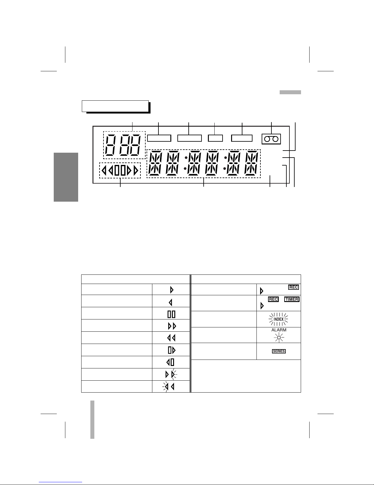
INDICATOR PANEL
1. TIME LAPSE VCR TIME Indication
2. ALARM Indication (ALARM REC ON
indication)
3. SERIES Indication
4. RECORD Indication
5. TIMER Indication
6. CASSETTE Indication
7. INDEX Indication
8. POWER FAILURE Indication
9. KEY LOCK indication
10. REPEAT Indication
11. FUNCTION Indication
(CLOCK, TAPE COUNTER, ERROR)
12. VCR FUNCTION Indication
VCR FUNCTION Indication
PLAYBACK INDICATION RECORDING INDICATION
PLAYBACK
REVERSE PLAYBACK
PAUSE STILL
FAST FORWARD
REWIND
CUE
REVIEW
RECORDING
TIMER RECORDING
ALARM INDEX
ALARM RECORDING
SERIES RECORDING
FORWARD SLOW PICTURE/
FORWARD FIELD ADVANCE
REVERSE SLOW PICTURE/
REVERSE FIELD ADVANCE
CONTROL NAMES AND LOCATIONS (Cont’d)
12 34 5 67
12 11 10 9 8
7
PREPARATION
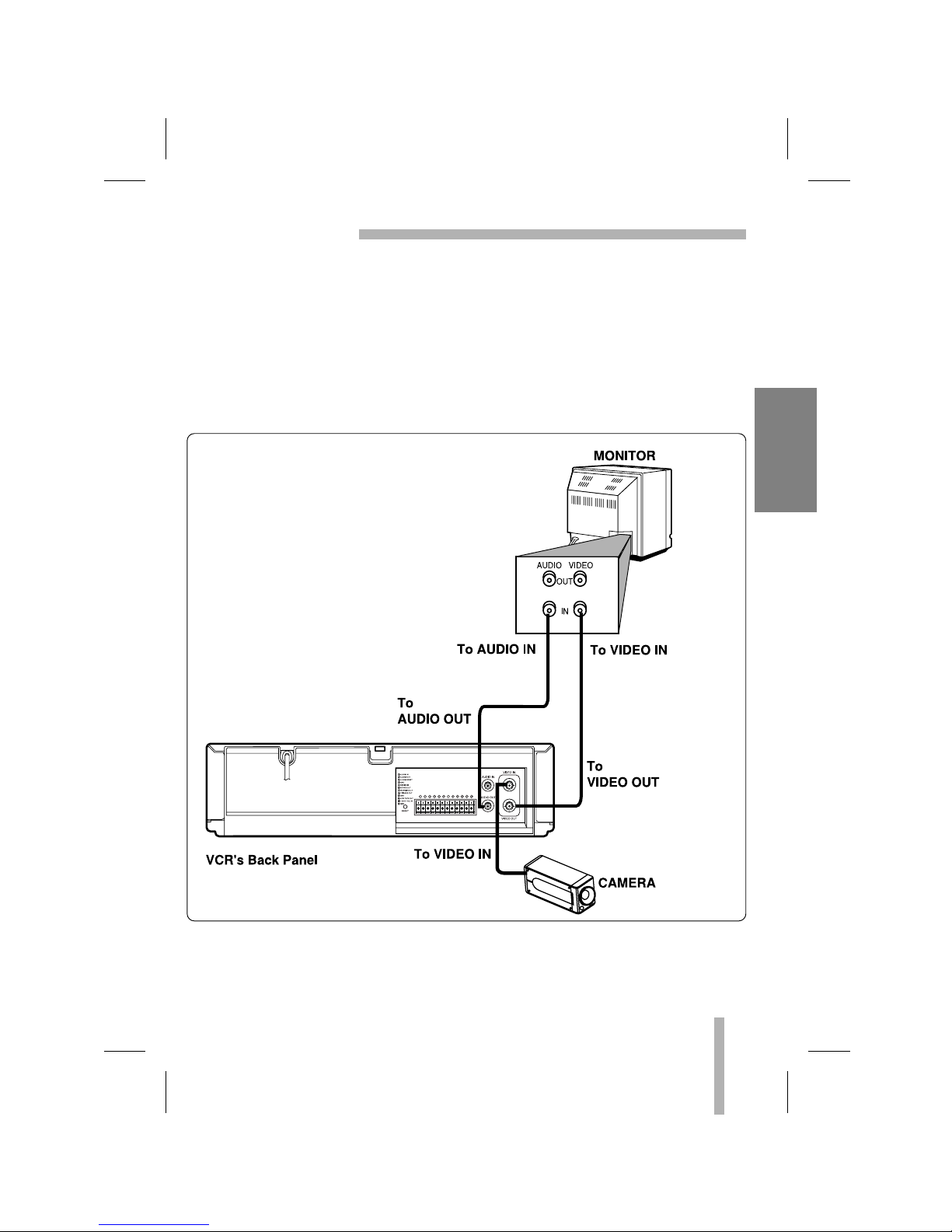
INSTALLATION
VCR TO MONITOR AND CCD CAMERA CONNECTION
•
Connect your VCR’s AUDIO/VIDEO output jacks to the A/V input jacks on back of your
monitor.
If your monitor does not have A/V input jacks, exchange the monitor or TV for one with A/V
input jacks.
•Connect the CCD camera to VCR’s VIDEO input jack.
•The cables for audio and video connection are not provided with your VCR.

8
PREPARATION
MULTIPLEXER CONNECTIONS
If the multiplexer has two output terminals (MONITOR OUT, PB OUT), connect Monitor to the PB
OUT terminal if you want to see the playback picture.
To use the multiplexer and trigger function properly, refer to the multiplexer instruction manual.
HOW TO CONNECT SWITCHER WITH TRIGGER INPUT TERMINAL
This manual suits for next models
1
Table of contents
Other Ganz VCR System manuals


