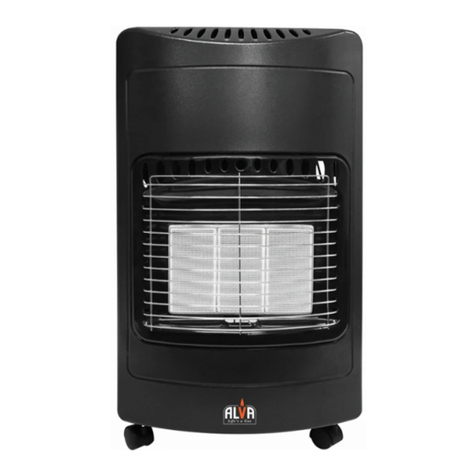
Gasolec G12 User manual

G12 Instruction Manual
The Best in
Growheating
GAMECO (NSW) PTY LTD
161 Parramatta Road
AUBURN NSW 2144
Phone: 02-96485856
GAMECO (Victoria)
65A Chifley Drive
PRESTON VIC 3072
Phone: 03-94803633
GAMECO QUEENSLAND
17 Roy Street
MILTON QLD 4064
Phone: 07-33777999
GAMECO NEW ZEALAND LTD
9 Villa Street
Masterton NZ
Phone 06-3701683

Gameco G12
2
GAMECO/GASOLEC warrants the Gasolec Heaters and Temperature Control Systems for a period of twelve months
from date of purchase to be free of defects in materials and workmanship subject to our normal terms and conditions
of trading.
Without charge to the customer, Gameco will repair or replace any components found to be defective in materials or
workmanship in the GAMECO/GASOLEC product range provided that the same has been returned to Gameco or an
authorized agent within the warranty period.
The warranty is subject to:
A) The product or parts thereof has not been subject to abuse, neglect, accident, improper installation or
servicing or used in violation of the relevant Standards/Codes or instructions provided by Gameco.
B) The product has not been repaired or altered outside the factory or authorized repair station.
C) The product being found, in the reasonable judgment of Gameco, to have a defect in materials or
workmanship, which has developed under normal installation, use and service.
GAMECO/GASOLEC assumes no responsibility for the costs of removal and installation of the product or other
incidental costs which may arise as a result of any defects in materials or workmanship.
This is an overview of Gameco’s sole warranty with respect to the products delivered hereunder. No statement,
representation, agreement or understanding, oral or written, made by an agent, distributor, representative or
employee of Gameco, which is not contained in this warranty, will be binding upon Gameco, unless made in writing
and executed by an authorised Gameco employee. Gameco makes no other warranty of any kind whatsoever,
expressed or implied, and all implied warranties of merchantability and fitness for a particular use which exceed the
aforestated obligation are hereby disclaimed by Gameco and excluded from this agreement. Gameco assumes no
liability for the loss of life, property or income caused by the misuse of its products.
A full copy of our Terms and Conditions of Trading is available on request.
GAMECO(NSW)PTYLTD
PO Box 156 Auburn NSW 2144
Ph (02) 9648 5856 Fax (02) 9647 2784

Gameco G12
3
Open space above G12 to be a minimum of 1 metre
NOTE:
Do not instal a heater directly below a gas pipe.
A gas hose should never be above or below a heater
and positioned to minimise radiant heat affects.
TO BE INSTALLED ONLY BY AN AUTHORISED PERSON
DO NOT PLACE
ARTICLES ON OR
AGAINST THIS
APPLIANCE
DO NOT USE OR STORE
FLAMMABLE MATERIALS
NEAR THIS APPLIANCE
DO NOT SPRAY
AEROSOLS IN THE VICINITY
OF THIS APPLIANCE WHILE
IT IS IN OPERATION

Gameco G12
4
Introduction
Read this manual before installing, using or servicing the G12 gas heater.
Refer to section Additional Safety Precautions for operational warnings.
The Gasolec G12 heater is only intended for use in livestock applications.
Models
AGA approval no 7718
For use with ULPG
G12-TM-LP With stand alone thermostat control
G12TSLP With 24AC/12v DC solenoid valve control
For use with Natural Gas
G12-TM-NG With stand alone thermostat control
Gas rating 45 Mj/hr
Gas Connection:
The gas connection is located on the gas control valve.
For ULPG 3/8 BSP male connection.
For natural gas ½” BSP male connection.
The heater has a circular reflector with a diameter of 570mm. Giving a circular heating
pattern of approximately 12 meters diameter.
The heater weighs, 6.5 kg with filter.
Overall heater dimensions

Gameco G12
5
Installation
Installation of the G12 heater should be undertaken by an authorised person in accordance
with Australian standard AS5601 Gas Installations and must also comply with local and
statutory and regulatory requirements.
The heater is to be mounted in an area with adequate ventilation. Ventilation requirements
must be in accordance with AS5601. Gas Installations and must also comply with local
statutory and regulatory requirements.
The gas piping system for heaters using LPG must have an approved gas regulator fitted to
give a supply pressure to the heater inlet of 2.75 kPa. Use the pressure tapping point located
at the gas inlet on the Maxitrol valve to check inlet pressure.
The gas piping system for heaters using NG must have an approved appliance gas regulator
fitted to give a supply pressure to the heater inlet of 1.00 kPa. Use the pressure tapping
point on the appliance regulator to check the inlet pressure.
A 3m long hose certified to AS/NZS 1869 Class C is supplied and must be used to connect
the heater to the gas supply. The hose shall be installed to ensure it is not exposed to
excessive radiant heat and placed so there is no undue strain on the hose during operation.
Installation Height from floor: 1.5 -1.7 meter to bottom of reflector
Air gap above heater 1.0 meter minimum overhead clearance
Distance to any combustible product: 1.5 meter minimum
1. Before burner ignition, ensure that gas is present at the burner inlet and check that
all gas connections are gas tight and there are no leaks. Use a soapy water
mixture or other approved leak check solution to ensure all fittings are sealed. Any
tell tale bubbles will mean the joint is not sealed; undo the joint, check the sealing
faces and threads for damage. Reseal and recheck for tightness. Ensure the soap
solution does not contain any traces of AMMONIA in the mixture. Ammonia can
have a detrimental effect on the brass joint.
2. Check the hose is not kinked or damaged.
3. The temperature sensing bulb on the G12-TM model should be swivelled down
toward the floor to allow the bulb to sense air temperature away from the heater.
4. On completion of installation the heater must be tested and commissioned.
Lighting
Model G12-TM
1. Slide pilot cover open or off to expose pilot burner. (Fig1)
2. Push in and turn the control knob on the thermostat to PILOT, this releases gas to
the pilot burner. (Fig 3)
3. While holding the control in, light the pilot burner (Fig2). The pilot flame should
play onto the tip of the thermocouple.
After 5-10 seconds, release the pilot button, the pilot flame should remain alight.
Check that the pilot flame is stable, refit the pilot cover and slide closed.
4. Turn the Control Knob to ON position, and turn the numbered dial to position 7,
this will release gas to the burner.
5. The main gas will ignite smoothly from the pilot flame, the flame should be blue in
colour with no yellow flame present. The flame will establish and start to warm
the heat emitter. After a while the heater will come up to temperature, and the
emitter will glow red.

Gameco G12
6
6. The control knob should be turned to the number that gives the required operating
temperature.
7. When the surrounding area has reached temperature, the control valve will shut
the gas off to the heater. The main flame will go out leaving the pilot flame intact to
relight the main flame when required.
8. As the surrounding temperature falls the sensor will reopen the control valve
allowing the main burner to re-ignite.
Closed Open
Fig 1 Pilot cover Fig 2 Lighting Pilot
Fig 3 Thermostat Fig 4 Flame Failure Valve
Model G12-S
1. Slide pilot cover out or off to expose the pilot burner (Fig1)
2. Push in the button on the flame failure valve; this will release gas to the pilot
burner (Fig 4).
3. While holding the button in,light the pilot burner (Fig2), the pilot flame should play
onto the tip of the thermocouple. After 5-10 seconds release the button and the
pilot flame should remain alight. After checking that the flame is stable, refit and
slide the pilot cover closed.
4. Set the shed controller to the desired temperature.
5. The controller will signal the solenoid valve on the heater to open and put gas to
the heater. The gas will ignite smoothly from the pilot flame, the flame should be
blue in colour with no yellow flame present. The flame will establish and start to
warm the heat emitter. After a while the heater will come up to temperature, and
the emitter will glow red.
When the surrounding area has reached temperature, the solenoid control valve
will shut the gas off to the heater. The main flame will go out leaving the pilot flame
intact to relight the main flame when required.
Caution. : The temperature setting selected will determine if the solenoid valve has opened,
while the pilot flame is being established. Be aware that main gas flame could ignite on

Gameco G12
7
release of the pilot button.
Maintenance
1. Good maintenance is essential for safe operation and heating efficiency.
2. Isolate gas and power supply if required, from the heater before undertaking any
maintenance on the heater.
3. Dusty heaters and filters reduce burner efficiency and durability. One of the visible
characteristics of a dusty blocked filter, is the appearance of a yellow, wandering
flame. This indicates that combustion air is not being drawn in through the air filter
in enough quantity to create clean combustion and a blue gas flame. For this
reason the filter should be removed and cleaned on a regular basis. The
frequency will depend on the type of litter in the shed and the dust created during
each batch.
4. At the end of each batch, thoroughly clean the heater and filter of all dust and dirt.
5. A large plastic bag can be used to keep the heater clean between batches.
7. The filter supplied with the G12 is washable in water. Ensure it is dried before
reuse.
8. The flexible gas hose should be checked regularly for signs of wear or damage.
The hose should be replaced if it is damaged.
9. The appliance should be checked for clean combustion and correct operation by a
qualified service person once a year.
Trouble shooting
1. If the gas flame is soft and yellow, refer to previous section on heater
maintenance.
2.
If the pilot fails to light, first check to see that gas is present at the inlet and is at the
correct pressure.
3. Check that the pilot orifice is clear, clean or replace if blocked.
4. If the pilot light does not remain lit after releasing the control button, check that the pilot
flame is touching the end of the thermocouple and is not blowing away from the tip during
light up. Check that the thermocouple connection into the control valve is not loose but
also not over tightened.
5. If the heater does not appear to reach full heat, check to see if the control valve is set to
the correct mark. The main temperature control system is set to the desired temperature.
The gas is supplied at the correct pressure.
The power supply is at the correct voltage to the solenoid valve.
Problems not covered in this document, should be referred to your gas technician or
Gasolec dealer.
Caution: Never check for gas leaks with an open
flame.
Ventilation
This heater is not designed to be used in a room smaller than 225 cubic meters.
This is the volume required for each heater in a multiple heater installation.
The heater must only be used in a properly ventilated area.
For each heater two permanent openings for fresh air are required, at roof and floor positions.
Each opening to have a minimum area of 135 cm
2
.

Gameco G12
8
Additional Safety Precautions
1. Use caution when working near or inspecting the heaters. Surfaces of the heater
are very hot during operation and just after shut down.
2. Do not store any flammable or combustible materials near the heater.
3. Electrical cabling and gas supply hose must be supported up and away from the
heater to prevent damage by radiant heat.
4. Check all gas pipe and gas hose connections for leaks with soap and water
solution or other leak check solution. See Installation, section 1
NEVER check for leaks with an naked flame.
5. Ventilation air and combustion air must not be obstructed.
6. Do not adjust the height; maintain or repair the heater while it is still hot.
7. Never bypass any safety devices.
8. Do not operate a heater if you suspect there are combustible liquids or vapours,
present.
9. Warning: Certain materials or items, when stored under or near this appliance will
be subject to radiant heat and could be seriously damaged.

Gameco G12
9

Gameco G12
10
Table of contents
Popular Gas Heater manuals by other brands

Carrier
Carrier 48GS Guide Operating and maintaining guide

Desa
Desa GN30 Safety information and installation manual

Desa
Desa Vanguard VP600BA OWNER'S OPERATION AND INSTALLATION MANUAL

Vermont Castings
Vermont Castings RADVTCB Homeowner's installation and operating manual

Hiland
Hiland 199-FF-31600 owner's manual

Modine Manufacturing
Modine Manufacturing HD owner's manual

COZY
COZY BFT101 and Installation and operation instructions

Desa
Desa REM10PT OWNER'S OPERATION AND INSTALLATION MANUAL

Dru
Dru ESTATE 02 Instructions for installation and operation

Desa
Desa VN10TA OWNER'S OPERATION AND INSTALLATION MANUAL

Brixton
Brixton KA-5319 manual

Master
Master BLP 11 User and Maintenance Book