GCE VECTREX HP-3000 User manual

G
..
C.E. VECTREX SERVICE MANUAL
TABLE OF CONTENTS
I.
SPECIFICATIONS
.......................................................
1
11.
OPERATING
INSTRUCTIONS
............................................
2
II!.
MAINTENANCE
AND
SAFETY TIPS
......................................
7
IV. TV
AND
RADIO
INTERFERENCE
.........................................
7
V.
CIRCUIT
DESCRIPTION
.................................................
8
VI. DISASSEMBLY
..................................................
,
.......
11
A.
Back
Cover
Removal
.........................................•..
,.
. ..
11
8.
Power
Board
Removal . :
.............................................
11
C.
Logic
Board
Removal
...............................................
11
O.
Power
Transformer
Removal
.........................................
11
E.
Speaker Removal . . . . . .. . . . . . . . .. . .. . . . . . .. . . . . . . . . . . . . . . . . . . .. .. . .. 12
VII.
LOGIC
BOARD
ADJUSTMENTS
.........................................
12
Logic
Board
Component
Layout
.....................................
13
VIII. POWER
BOARD
ADJUSTMENTS
........................................
15
Power
Board
Component
Layout
......
,.
............................
14
IX.
CRT
/YOKE
REMOVAL
AND
SET-UP
.....................................
16
X.
HAND
CONTROL
OISASSEMBLY
.......................................
16
Hand
Control
Schematic
. . . . .. . .. . .. . .. . . . . . . .. . .. . . . . .. . . . . . . . . . . . . 17
XI.
TEST
CARTRIDGE
PROCEDURE
........................................
18
XI
I.
PARTS
LIST
............................................................
22
Xl!
I.
BLOCK
DIAGRAM
............................................
,
.........
29
POWER
BOARD
SCHEMATIC
...........................................
30
LOGIC
BOARD
SCHEMATIC
............................................
31
PACKAGING
....................................
,,
......................
32

t
SPECIFICATIONS
VECTREX
is a
self-contained,
microprocessor
based,
Vector
Display,
portable
home
video
game
arcade
with
external
game
cartridge
program
capability.
MPU
68A09
BK
X 8
BIT
DATA·-
16
BIT
ADDRESS
INTERNAL
ROM
2363 8K X 8
BIT
Pl
EASE
NOTE:
INTERNAL
ROM
2114 (2)
1K
X 4
BIT
(ea.)
INTERNAL
ROM
2114
should
read:
EXTERNAL
ROM
(GAME
CARTRIDGE)
8K X 8
BIT
CAPABILITY
INTERNAL
_l3f\l1
2114
CRT:
SAMSUNG
240R840
90
DEG.
DEF.
B&W
VECTOR
DEFLECTION
12
EXTERNAL
GAME
CARTRIDGES
CURRENTLY
1
RESIDENT
GAME
Second
Controller
available
as an
accessory
Game
Cartridges
include
a
screen
overlay.
120V
AC
-60Hz
DIMENSIONS:
9¾
X 11½ X
14%
WEIGHT:
15 Lbs.
-1-
(2)
(2)

11.
OPERATING INSTRUCTIONS
UNPACKING
When
you
remove
your
Vectrex
Arcade
System
from
the
box
you
should
have these items:
Vectrex Arcade System
Console with Built-in
Control Panel Attached
Owner's Manual
r
......
,,.,
I
,
)
!
I
+-•-
,
__
'
j-
i·
.
Owner's Club
Registration Card
~
...
...,...,,.;,,
..
-4
4
◄
n:-~
lnsttuc!"IO\--S
4
v
...........
Screen Overlay
&
Instructions
for
Mine StormT" Game
IMPORTANT:
To
prevent overheating. never block the ventilation openings on
the back orbottom ofthe console. These openingshave been designed to provide
proper ventilation during operation and should not
be
enclosed or covered in
any way.
Before
inserting
the
plug, make
sure
the
console
switch
is OFF.
The
unit
will
work
in any 120
Volt
AC
60
Hz
electrical
outlet.
Using
any
other
power
supply
will
damage
the
unit. As a special safety
feature,
the
plug
is
polarized
so
that
it
will
fit
into
standard
AC
outlets
in
one
direction
only.
If
the
plug
does
not
slip
easily
into
the
outlet,
turn
it
over and insert again.
It's a
good
idea
to
save
the
box
and
styrofoam
inserts
in
case
you
ever need
to
move
or
ship
your
Vectrex
Arcade
System.
-2-

SETTING UP
Vectrex
Arcade
System is designed
for
table-top
use.
For
the
mostenjoyment, select a
location
where
the
screen will be at
about
eye level when
you
are
playing
the games.
A
sturdy
table, desk
or
shelf
is suggested.
Do
not
operate
console
on
a bed, sofa. carpet, etc.
THE
CONTROLS
Control Panel Storage
To
remove
control
panel
from
the storage area
at
the
bottom
of
the
console, press
the
release
tab
and
the
panel will
drop
down.
To
return
control
panel
to
its storage area:
•
Coil
the
cord
once
around
the
joystick
and then on
top
of
the
action
buttons.
•
Slide
the panel
onto
the
tabs
at
the
bottom
of
the
console.
• Flip
up
the
panel
until
it
clicks
into
place.
-3-

l
~~JJ
Reset
Button
Press Outlet
r+/4--+---
for Built-in
to
restart
--1--1-.--JWi.Jl.H+ff+ilf.+.--
Control
Panel
games.
Outlet for Second Control Panel
__
....,
Second
control
panel (sold separately)
used in games that
offer
simultaneous
two-player
game play.
Note:
Control
panels are detachable.
The
plugs
fit
intooutletsone
way
only-
do
not
force
them.
Control Panel
Self-Centering Joystick
Directional
control
for
those games in
which
direction
is a factor. For
specific
use, refer
to
instruction
manual and screen overlay
for
each game.
Off/On/Volume Control
Turn
clockwise
to
turn
on
and increase
volume.
----
Connecting Cord
To
avoid
permanently
overstretching
the coi!ed cord,
it
should
not
be
pulled
out
to
itsextremelength
for
an extended
period
of
time.
4 Action Buttons
The
functions
of
each
button
depend on the
game
cartridge
being used. For
specific
uses,
refer to
instruction
manual and screen overlay
for
each
game.
fl]
l\
I\
I\.
\ll'l
1
'I.
Ill
.
\\
~
~
ij
ij
~
~
ij
U Brightness Control {on back
of
console)
0
~
Turn
clockwise
for
brighter
picture.
Turn
counterclockwise
to
reduce brightness.
For
maximum
performance,
brightness
should
!\
~.
0
.,
~
r.i
i---
be
adjusted
so
that
white
dot
does
NOT
appear
II
Ii
ll
II
fl
I
,n
center
of
screen.
THE
CONTROLS
-4-

INSERTING AND REMOVING
GAME
CARTRIDGES
IMPORTANT:
TO
PROLONG
THE
LIFE OF YOUR VECTREX
ARCADE
SYSTEM
AND
PROTECT
THE
ELECTRONIC
COMPONENTS,
THE
CONSOLE
SHOULD
BE
TURNED
OFF
WHEN
INSERT-
ING
ANO
REMOVING
CARTR.IDGES.
TO INSERT CARTRIDGE
• Make
sure
the
console's
power
is
turned
OFF.
•
Hold
the
cartridge
with
the
label side up.
•
Insert
cartridge
carefully
into
the
slot
on the
right
side
of
the
console.
•
Be
sure
the
cartridge
is
firmly
inserted to the
guideline
marked on
the
cartridge.
TO
REMOVE CARTRIDGE
•
Make
sure
the
console's
power
is
turned
OFF.
•
Pull
the
cartridge
straight
out
of
the
slot
•
To
protect
the
electronic
components,
the
cartridge
should
be stored in
the
original
package
or
other
suitable container.
IMPORTANT:
Unlike
a
conventional
TV
screen, the screen
built
into
the Vectrex
console
uses an
advanced
display
technology
to
achieve
brilliantly
clear
images and special visual effects like
rotation
and zooming. Due
to
this
special
display
technology,
it
may appear
that
the
images pulse
THIS
SLIGHT
PULSING
IS
NORMAL
AND
DOES
NOT
INDICATE
A PROBLEM
WITH
CONSOLE.
The
screen overlays
that
are provided
with
each
cartridge
have been
specially
to
virtually
eliminate
the
slight
pulsing.
-5-

INSERTING AND REMOVING SCREEN OVERLAYS
Tabs
TO
INSERT SCREEN OVERLAY
•
Slip
the
bottom
of
the
screen
overlay
behind
the
two
tabs at
the
bottom
of
the screen.
•
Push
the
top
of
the
overlay
down
slightly
using
the
finger
area at the
top
and press against
the
tabs
at
the
top
until
the
overlay snaps
into
place
under
the
tabs.
TO
REMOVE SCREEN OVERLAY
• Place
your
finger
In
the
curved area
at
the
top
of
the
overlay, press
down
slightly
and
pull
the
overlay
straight
out.
• Store
the
overlay in
the
original
package
or
other
suitable
container.
STARTING GAME PLAY
•
Make
sure
the
cartridge
and
screen overlay are inserted properly.
NOTE: A cartridge is
not
needed
to
play
Mine
Storm,
which
is
the
game
built
into
the
console.
•
Turn
the
OFF/ON/VOLUME
CONTROL
to
the
ON
position
(clockwise).
You
will
see
the
Vectrex
title
for
a few seconds,
then
the
name
of
the
game.
•
Adjust
the
volume
control
1o
the
desired
listening
level.
• Refer to the individual game
instructions
for
game play details.
-6-

111.
MAINTENANCE AND SAFETY TIPS
Vectrex Arcade System
will
bring
you
many years
of
fun
and excitement. In
order
to
keep
Veci:rex Arcade System in
good
working
condition,
please remember the
following:
•
Proper
ventilation
is very
important
to prevent overheating.
Never
block
the
ventilation
openings
on
the
back
of
the
console
in
any
way.
There
are alsoventilationslots
on
the
bottom
which
should
not
be
blocked
by
placing
the
console
on a bed, sofa, carpet, etc.
• Be careful
not
to
spiH
liquids
on
the
console, cartridges
or
control
panel and never expose the
unit
to
rain
or
excessive moisture.
If
this
happens,
unplug
the
console,
wipe
the
outside
dry,
and
then
let
unit
air
dry
for
at least 48
hours
before using
it
again.
• Do
not
expose the console,
cartridges
or
control
panel
to
excessive
or
extreme heat. Neverplace
the
unit
near
or
over a radiator
or
heat system.
• Never remove the back
cover
of
the console
or
drop
or
push objects
through
the slots in the
back cover.
This
could
expose
you
to
very
high
voltage.
•
If
the
console
is damaged,
shock
hazard may exist.
If
damaged
or
there is a
distinct
change
in
performance,
immediately
unplug
the console and have
it
checked
by
a
GCE
Authorized Service
Dealer.
• Care should be taken
not
to
drop
the console, cartridges
or
control
panel.
The
console
should
be lifted using
the
convenient handle at the
upper
rear
of
the
console.
• Always
turn
the
power
OFF when the
unit
is
not
in
use and before inserting
or
removing
car-
tridges.
Do
not
plug
into
a
power
source
other
than 120
Volt
AC 60 cycles electrical outlet.
• Clean the screen overlays and
the
exterior
of
the
console
with
a soft,
slightly
dampened cloth.
Before cleaning
the
console, make sure
the
unit
has been
turned
OFF and
the
power
cord
has
been disconnected. Never use a householdcleaner. cleanser
or
sprayon theoverlays
or
console.
IV.
TV
AND RADIO INTERFERENCE
The
Vectrex
console's
electronic
circuitry
generates signals
for
its
own
internal use
that
may
cause interference
to
nearby radio and television receivers.
The
Vectrex console has been
type
tested and is in
compliance
with
FCC Rules Part
15
Subpart
J
for
Class B
computing
devices.
However, interference may
occur
in certain installations.
If
interference does occur,
you
should
try
one
or
more
of
the
following
measures
to
correct
the
problem:
• Reorient the
TV
or
radio antenna.
• Move the Vectrex
console
further
from
the TV
or
radio.
•
Plug
the
Vectrex console
into
a
different
outlet
than the TV
or
radio.
• It
your
Vectrex dealer
or
an experienced
TV/radio
technician
for
additional
suggestions.
booklet
entitled
"How
to
Identify
and Resolve Radio-TV Interference Problems" is avail-
the U.S. GovernmentPrinting Office, Washington, D.C. 20402, StockNo.004-000-00345-4.
'
-7-
V.
CIRCUIT
DESCRIPTION
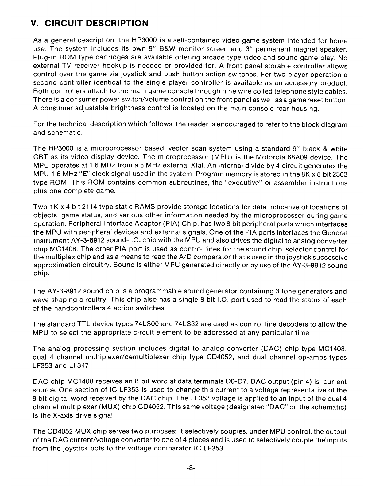
As a general
description,
the
HP3000
is
a
self-contained
video
game system
intended
for
home
use.
The
system
includes
its
own
9"
B&W
monitor
screen
and
3"
permanent
magnet
speaker.
Plug-in
ROM
type
cartridges
are available
offering
arcade
type
video
and
sound
game play.
No
external TV receiver
hookup
is needed
or
provided
for. A
front
panel
storable
controller
allows
control
over
the
game
via
joystick
and
push
button
action
switches.
For
two
player
operation
a
second
controller
identical
to
the
single
player
controller
is available as an accessory
product.
Both
controllers
attach
to
the
main
game
console
through
nine
wire
coiled
telephone
style
cables.
There
is
a
consumer
power
switch/volume
control
on the
front
panel as well as a gamereset
button.
A
consumer
adjustable
brightness
control
is located on
the
main
console
rear
housing.
For
the
technical
description
which
follows,
the
reader is
encouraged
to
refer
to
the
block
diagram
and schematic.
The
HP3000 is a
microprocessor
based,
vector
scan system
using
a standard
9"
black
&
white
CRT
as its
video
display
device.
The
microprocessor
(MPU) is
the
Motorola
68A09 device.
The
MPU operates at 1.6
MHz
from
a 6
MHz
external Xtal.
An
internal
divide
by
4
circuit
generates
the
MPU 1.6
MHz
"E"
clock
signal used in
the
system.
Program
memory
is stored in
the
8K
x 8
bit
2363
type
ROM.
This
ROM
contains
common
subroutines,
the
"executive"
or
assembler
instructions
plus
one
complete
game.
Two
1K x 4
bit
2114
type
static RAMS
provide
storage
locations
for
data
indicative
of
locations
of
objects,
game
status, and
various
other
information
needed
by
the
microprocessor
during
game
operation.
Peripheral
Interface
Adaptor
(PIA)
Chip,
has
two
8
bit
peripheral
ports
which
interfaces
the
MPU
with
peripheral devices and external signals.
One
of
the PIA
ports
interfaces
the
General
Instrument
AY-3-8912
sound-1.0.
chip
with
the
MPU and also
drives
the
digital
to
analog
converter
chip
MC1408.
The
other
PIA
port
is used as
control
lines
for
the
sound
chip,
selector
control
for
the
multiplex
chip
and as a means
to
read the A/O
comparator
that's used in the
joystick
successive
approximation
circuitry.
Sound
is
either
MPU generated
directly
or
by use
of
the
AY-3-8912
sound
chip.
The
AY-3-8912
sound
chip
is a
programmable
sound
generator
containing
3
tone
generators
and
wave
shaping
circuitry.
This
chip
also has a
single
8
bit
1.0.
port
used
to
read
the
status
of
each
of
the
handcontrollers
4
action
switches.
The
standard
TTL
device
types
74LS00 and 74LS32 are used as
control
line
decoders
to
allow
the
MPU
to
select
the
appropriate
circuit
element
to
be addressed at any
particular
time.
The
analog
processing
section
includes
digital
to
analog
converter
(OAC)
chip
type
MC1408,
dual
4
channel
multiplexer/demultiplexer
chip
type
CO4052, and dual channel
op-amps
types
LF353 and LF347.
OAC
chip
MC1408 receives an 8
bit
word
at
data
terminals
00-07.
DAC
output
(pin
4) is
current
source.
One
section
of
IC LF353 is used
to
change
this
current
to
a voltage representative
of
the
8
bit
digital
word
received
by
the
OAC
chip.
The
LF353
voltage
is
applied
to
an
input
of
the
dual 4
channel
multiplexer
(MUX)
chip
CO4052.
This
same voltage (designated
"OAC"
on the schematic}
is
the
X-axis
drive
signal.
The
CD4052
MUX
chip
serves
two
purposes: it selectively couples,
under
MPU
control,
the
output
of
the
DAC
current/voltage
converter
to
o:,e
of
4 places and is used
to
selectively
couple
the'inputs
from
the
joystick
pots
to
the
voltage
comparator
IC LF353.
-8-

4
places
to
which
the
"DAC"
signal
is
coupled
by
the
MUX
are:
Y-axis
sample
and
hold
IC
LF347
The
"O"
reference
charge
capacitor
The
2-axis
(brightness
signal)
sample
and
hold
IC
LF347
MPU
sound
resistive
matrix
Each
of
these
4
signals
is a
voltage
value
representative
of
the8
bit
DAC
input
word
for
that
function.
The
joystick
pot
positions
aresensed
by
a
successive
approximation
process.
The
MUX
chip
selects
each
joystick
pot
input
line
and
applies
it
to
the
plus
input
of
comparator
IC
LF353.
At
the
same
time
the
MPU
generates
digital
words
that
are changed
to
voltages
by
the
DAC
and
current/voltage
converter
mentioned
previously.
These
voltages
are
successfully
applied
to
the
comparator's
minus
input
until
the
MPU
generated
voltage
is equal
to
the
joystick
voltage.
The
MPU
then
recog-
nizes
the
digital
word
representative
of
the
comparison
voltage
and
is
able
to
establish
a
location
for
the
joystick
pot.
The
present
position
for
each
joystick
pot
is sensed
in
this
manner.
The
pot
position
information
is
updated
on
a
regular
basis
by
the
MPU.
Returning
to
the
X and Y axis
drive
signals, these
signals
are
applied
to
X,Y
integrator
IC
LF347
negative
input
pins
through
series
analog
switch
types
4066B.
The
"zero"
reference
signal
is
applied
to
the
positive
inputs
of
the
integrators.
There
are
also
analog
switches
across
the
integrator
IC
capacitors.
The
series analog
switches
are
controlled
by
MPU
signal
RAMP and
the
parallel capaci-
tor
swrtches
are
controlled
by
MPU
signal
Zero
10.
RAMP
10
determines
when
and
for
how
long
the
X
and
Y axis
voltage
levels
will
be
applied
to
the
integrator
amps.
Zero
10 is used
to
discharge
the
X & Y axis
integrator
caps
thus
initializing
them
for
the
next
signal
to
be
integrated.
The
outputs
of
the
X,Y
axis
integrators
are
coupled
through
J-FET
switches
to
IC
LM379
deflection
amplifiers.
The
LM379
operates
as a
voltage
to
current
driver,
1he
current
through
the
deflection
coils
forming
the
electromagnetic
field
which
deflects
the
CRT
beam.
To
protect
the
CRT
from
spot
burn
in
the
event
of
a loss
of
deflection,
the
Y axis
drive
amplifiers
output
is
detected
and
a
deflection
enable/disable
signal
generated.
This
signal
controls
the
J-FET
switches
in series
with
the
X,Y
deflection amp inputs
to
reduce the scan drive signal in the event
of
a
software
or
hardware
failure
plus
discrete
transistor
type
2SC1921
operates
to
bias
off
the
CRT.
Conventional
full
wave
rectification
and
three
terminal
regulators
are
used
in
the
low
voltage
power
supply,
A
special
negative
DC
source
is
generated
by
a
voltage
double-circuit
which
is
used
to
supply
a 13V
to
the
DAC
chip.
The
high
voltage
is
generated
via an
oscillator,
drive
transistor
and
flyback
type
transformer
cir-
cuitry
similar
to
what
is
commonly
used
in
small
black
and
white
TV
receivers.
Judicious
use
of
bypass caps, RF
filter
chokes,
ferrite
beads, etc., has been used in
the
design
to
control
RFI emissions.
-9-
I
....
0
I
f,
!
!
I .
l
i,___
-~
I
I~
ft
J
,
JJJ
I
I
f
I I
J I
I r
I I
J
I
I
I
I
I
I
I
I
I
I
/
I
I
I
\(
ITEM
DESCRIPTION PART
NO.
BAC"'~
CASE
A$SY
TCIC039
'I
SCR
t'N
iBACK TO
FRONT
CASE
ASSY)
U0002-2
3 SCREW {BACK
TO
FRONT
CASE ASSYI
1:'0002
3
4
5
G
KNQB
CLIP
KNOB,
VOUJW(
ONibFF
CONTfiO
L
LH1
A$SY
f
f10NT
CASE
AiiSY
POVVf:.F-i"PC6
BKACK!:".·f
ASSY
SCREW IPWR
BRKT
TO
FRONT
CASE!
CABLE
ASSY
AUDIO
DlGITt,l
'ANAt
CC
P('.8 HK"< 1 A.SSY
CARLF
ASSY,
'JIDED
SCREW
iD
A Bf1K 1 TO
eRONT
C.t,,SFI
110010
I
100023-1
990007
1
100009-1
100089-1
1J000,l4
600139-2
1UU0(i9
i
GO{l{J1
31J-1
1JQ()(}4-5
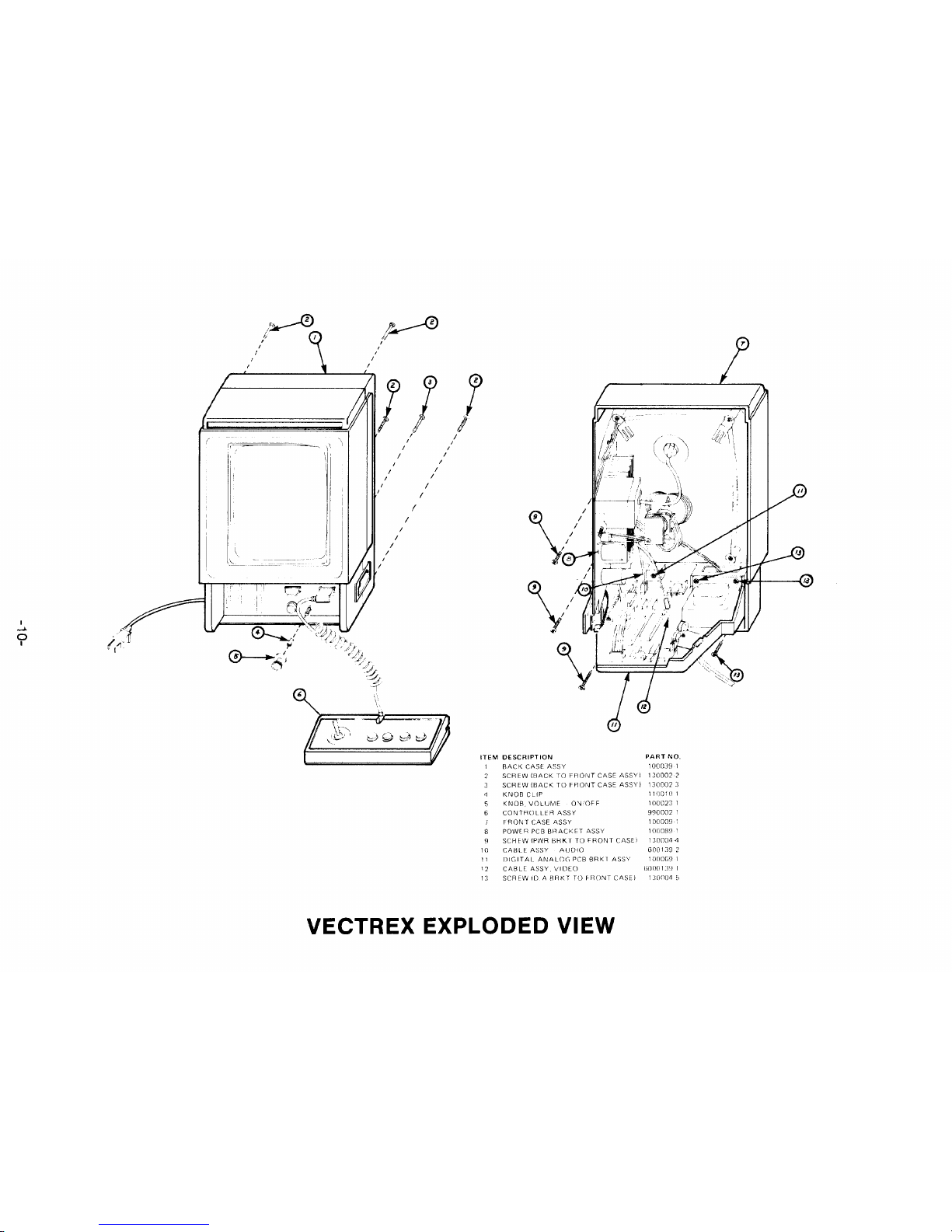
VECTREX EXPLODED VIEW

VI. DISASSEMBLY
A.
Back Cover Removal
1.
Lay
the
unit
on
a mat,
CRT
down.
2.
Remove
5
screws
from
the
back
cover.
3.
Remove
the
back
cover.
B. Power Board
Removal
1.
Remove
all
connectors
{5)
and
HV
lead
from
the
CRT.
2.
Unsolder
three
leads
(2 red, 1
white)
from
the
bottom
rear
of
the
board
at
location
EP104,
105
and
106.
(Note:
Two
of
these
three
leads
go
to
the
on/off
volume
control
switch,
the
white
lead
goes
to
the
power
transformer
(secondary
C.T.}
3.
Unsolder
the
Aquadag
ground
lead
from
the
top
rear
of
the
board.
4.
Unsolder
ground
jumper
(braid)
between
the
logic
board
and
power
board.
5.
Remove
two
small
Phillips
head
screws
from
the
bottom
of
the
board
that
secures
it
to
the
frame.
6.
Slide
board
back
and
remove
it
from
the
frame.
C. Logic Board Removal
1.
Remove
all
cable
connectors
from
the
top
of
the
board
(3).
2.
Unsolder
ground
jumper
between
the
logic
board
and
power
board
at the
logic
board
(left
side).
3.
Unsolder
and
remove
the
3
power
leads
at
the
power
board,
EP104, i 05
and
106.
Unsolder
2
of
these
leads
(red)
plus
2
from
the
power
transformer
on
the
back
of
the
on/off
switch.
4.
Remove
the
logic
board
mounting
frame
which
includes
the
speaker,
power
transformer
and
reset
buHon
by
removing
retaining
screws
that
hold
the
frame
to
the
front
cover.
There
are
two
screws
located
just
above
the
power
transformer
bracket
that
must
be
removed
also.
5.
Remove
the
logic
board
mounting
frame.
6.
Unsolder
the
leads
on
the
reset
button.
7.
Remove
the
retaining
hardware
on
the
front
of
the
volume
control,
on/off
switch.
8.
Remove
4
small
Phillips
head
screws
on
the
top
of
the
logic
board
that
hold
the
board
to
the
frame.
One
of
the
screws
holds
the
plastic
game
cartridge
guide
to
the
logic
board.
Remove
the
guide.
9.
Remove
the
logic
board.
D. Power Transformer Removal
MAKE
SURE
A/C
CORD
IS
UNPLUGGED
FROM
ALL
POWER
1.
Remove
the
small
screw
holding
the
fuse
cover
and
remove
the
cover.
2.
Remove
the
screw
in
the
center
of
the
Fuse
PCB
and
remove
the
PCB.
3.
Unsolder
the
2
power
and
two
primary
leads
from
the
fuse
PCB.
4.
Unsolder
and
remove
2 red leads
from
the
on/off
switch
mounted
behind
the
volume
control.
5.
Remove
the
splice
on
tile
white
lead
(secondary
C.T.).
6.
Remove
the
two
screws
holding
the
power
transformer
to
the
frame.
Note
the
ground
lead
on
the
right
hand
screw
(as
viewed
from
the
rear)
has a
ground
lug
on
it.
(See Page
12
for
Illustration)
-11-

POWER TRANSFORMER WIRING DIAGRAM
E. Speaker Removal
Follow
steps 1
thru
7
under
"Logic
Board
Removal."
1.
After the
frame
is
out,
remove 2
small
screws
from
the
top
of the speaker
grill
on the front
of
the
frame.
Lift
up
and
out
on
the
speaker
grill.
The
speaker
and
gril
I
will
come
out
as one.
2.
Unsolder
speaker leads,
note
colors
on+
and -
terminals
and
the
position
of
the
terminals
in relation
to
the
speaker
grill
and frame.
It
must
be replaced
the
same
way
for
lead
routing.
3.
Loosen
retaining
clip
holding the speaker in.
4.
Gently
slide
the
speaker
out
of
the
two
plastic
retaining
lips
and remove.
Rough
handling
at
this
point
will
break
these
two
plastic
retaining
lips
and cause
problems
in
securing
another
speaker in the assembly.
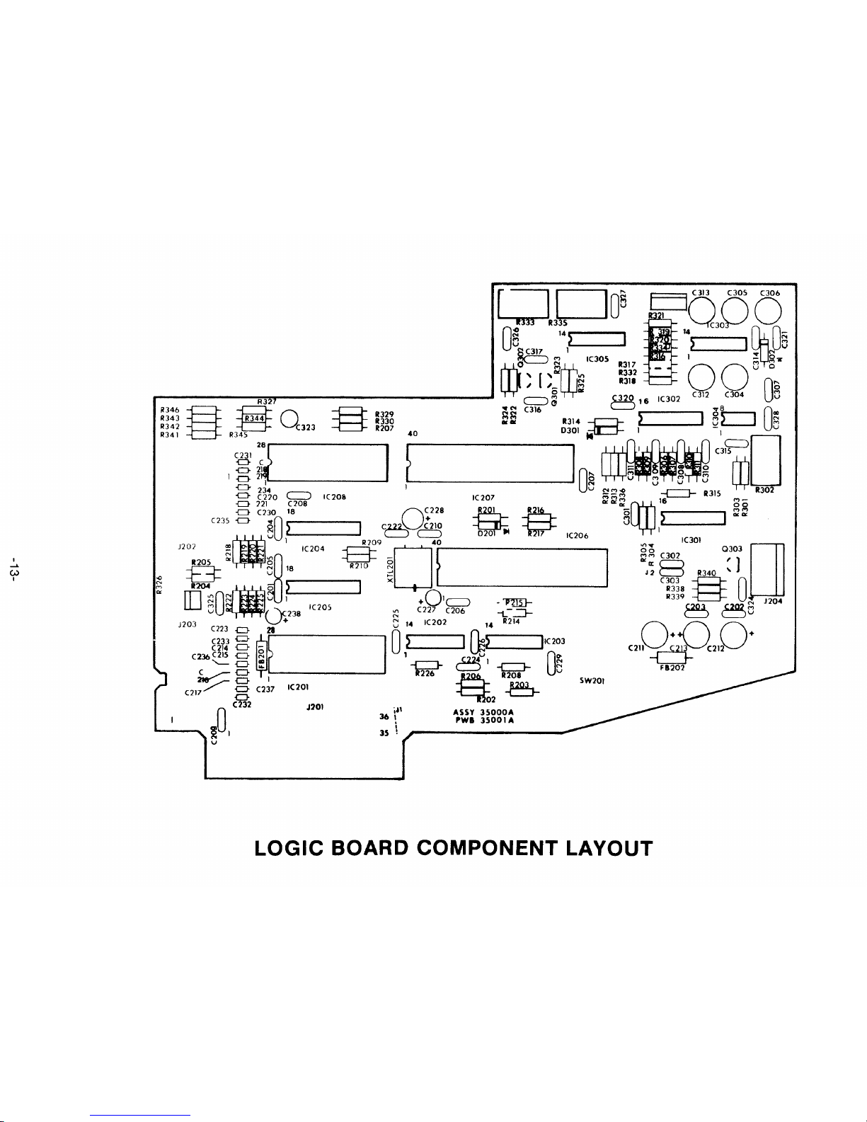
vn.
LOGIC BOARD ADJUSTMENTS
{See Test Cartridge Procedure, Page 18)
After
the
Logic
Board
has been replaced and installed
in
the
VECTREX,
the
following
adjustments
must
be made.
A.
Initial Power-up -Install Test Cartridge
1.
Plug
the
unit
in
and
turn
it on,
volume
as required.
The
CRT
should
display
GCE
title
page
and
introductory
tune
should
occur
within
fifteen
(15) seconds
of
power-up.
This
should
be
followed
by
the
test
cartridge's
title
page.
B.
Select ;'DAG Zero Test." These words will appear on the screen followed
by
ablank screen,
the
actual
adjustment
must
be
made
during
this
blank
screen interval. It
wiil
cycle
back
and
forth
between
the
word
display
and
blank
screen.
-12-
'
.....
(,>
I
§
U29
R330
R207
40
I
~
l
1003
LOGIC BOARD COMPONENT LAYOUT

T512
I
:
~..,
I C>
l
""
I C
I
I I
POWER BOARD
COMPONENT
LAYOUT
39P876
1P6591
2

Set
your
scope
on
"DC"
and
the
5mv/div
scale.
Connect
the
ground
lead
to
ground
on
the
board
and
conneci
the
probe
to
pin
1
of
IC
304,
adjust
R302 "DAC
OFFSET"
POT
for
OVDC.
After
the
adjustment
is
completed,
press
the
reset
button.
H
may
now
be necessary
to
recenter
the
picture
as
the
DAC
zeroing
will
affect
it. Use
the
centering
magnets
on
the
rear
of
the
deflection
yoke
and
the
"Linearity
Pattern"
in
the
test
cartridge
to set the
centering.
UNDER
NO
CIRCUMSTANCES
IS R302
"DAC
OFF-SET"
TO
BE
USED
TO
HELP
CENTER
THE
PICTURE.
C. Integrator Off-Set Test
Select
the
"Integrator
Off-Set"
test
Alternately
adjust
R333
"Y
Rate
Off-Set"
and R335
"X
Rate
Off-Set"
POTs
to
align
the
cross
bars
for
intersection
at
the
center
of
the
diamond
patterns.
The
bottom
row
of
diamonds
is
the
most
critical
and
should
be used
to
set these
controls
-
all patterns
should
be
within
one (1)
line
width.
D. Sound Test
Select
the
"Sound
Test."
The
display
will
say
"CHANNEL
A."
You
should
then
hear
the
sound
start
at a
low
frequency
and
increase in
frequency.
CHANNEL
Band
CHANNEL
C
will
follow
with
identical
tones.
The
next
title
on
the
CRT
will
be
"NOISE
ALL
CHANNELS"
and
this
will
be
noise
{static)
The
screen will remain
blank
and
two
(2) tones
will
be heard.
This
is
the
"CPU
SOUND"
check.
If
any
are
missing
the
board
must
be repaired.
VIII. POWER BOARD ADJUSTMENTS
After
installation
of
the
Power
Board
Assembly
make
the
following
checks
and,
if
necessary,
adjustments.
A. Install
the
Test
Cartridge
and
turn
the
VECTREX on.
The
GCE
title
page
on
the
CRT
and the
introductory
tune
should
occur
within
15 seconds.
B.
Tum
the
brightness
to
minimum
(R509)
and
measure the
high
voltage;
it
should
be
5.8KV+/-
150VDC.
C.
To
adjust
the
high
voltage,
connect
an
oscilloscope
to
T502
pin
7
and
set
the
vertical
at
20V
/div
and
the
horizontal
at
10
usec/div.
-15-
0
0
00
O.
Adjust
R526
for
minimum
ringing
in
the
displayed
wave
form.
E.
Recheck
the
H.V. and
adjust
R525
to
get
proper
reading
(5.SKV+/-
105VDC).
F. Repeat
the
adjustments
of
these
two
controls
until
proper
high
voltage
and
minimum
ringing
are
obtained.
G. Deflection Protect Circuit Check (Beam Cut Off)
Select
the
"Beam
Cut
Off"
Test.
Observe
CRT
monitor.
The
pattern
will
shrink
in size,
then
disappear.
In
approximately
2-3
seconds,
the
pattern
will
reappear
at
about
half-size
and
continues
to
increase
in size
and
brightness
until
it is
full-size,
then
the
cycle
will
repeat.
As the
pattern
decreases,
the
circuit
time
constraints
prevent
the
protect
switches
from
activating.
When
the
circuit
allows
the
switches
to
activate,
they
will
not
turn
on
until
the
brightness
and
deflection
reach
the
design
limits.
This
is
when
the
pattern
reappears
at
about
half-size.
H. Audio Amp.
Check
Select
the
"Sound
Test"
and
with
the
volume
control
set at
mid-range,
monitor
the
audio.
Sound
chip
channels
A,
8,
C,
and
CPU
sound
test
signals
must
be
audible
with
no
notice-
able
distortion.
IX. CRT/YOKE REMOVAL AND SET-UP
CRT
removal,
replacement
and
set-up
is
the
same
as
most
B/W
TV
tubes
in
most
respects.
The
primary
difference
is in
the
centering
technique.
After
the
CRT/yoke
has been
installed,
do
a
preliminary
centering
using
the
test
cartridge
linearity
pattern
for
a
display
and
the
centering
ring
magnets
on
the
yoke.
The
next
step
is
to
set
the
"DAC
ZERO"
as
directed
in
Paragraph
11
of
the
LOGIC
BOARD
ADJUST-
MENTS.
After
that
is
completed
again
recenter,
if
necessary,
with
the
ring
magnets
on
the
yoke.
Adjust
vertical
and
horizontal
height
so
the
linear
lines
are
at
the
top
and
bottom,
left
and
right
edges
of
the
CRT
and
front
cover.
Also
see R401
and
R408.
X.
HAND CONTROL DISASSEMBLV
A.
Remove
the
Hand
Controller
cord
from
the
port
in
the
Vectrex.
8.
Remove
the top inlay
by
inserting atool
between
it and the
case (use
extreme
caution
not
to
injure
yourself)
and
pry
up
one
edge.
Discard
the
tool
and
pull
the
inlay
off.
C.
Remove
the
five
(5}
screws
and
remove
the
top
cover.
D.
The
P/C
Board
can
be
removed
by
taking
out
the
screen
in
the
center
of
the
P/C
Board.
E.
The
buttons
and
pad
will
then
be
easily
removed.
-16-

W33
31
~
r /
JS601',,.
lx
I
6 -
~
B' A B s-
A y
®
VR-Y~
-<::::>-
VR-Y
VR-X AE,03
G G
®
0 y 8 -
R601
R603
L,.7K
L,.7
K CONTROL
BOX
P.CB
.
(BO
TT
OM
SIDE)
0 +sv
®
-
5V
@ 0
GND
CONTROL CABLE ·
d
cJl
d
cJl
A
i;:zzz:.
I
JOY-STICK
CONTROL
....
-..J
r J I
I
<D
0
CD
0
@
0
©
-~CONTROL
CABLE
PLUG
PIN
NO.
CONTROL
BOX
CONNECTION
CONTROL CABLE
COLOR
TO
CONTROL
P.C.B
.
PIN
NO.
WHITE
PIN
6
'-'PL=U,,__,G
'-=
CO,::..:N-=..:N~E::..:C:c_.:T_!CIO,::..:Nc:..----1~~
~
9
~
BROWN PIN 5
GRAY
PIN 7
BLUE PIN 9
BLACK PIN 8
GREEN PIN 1
YELLOW
PIN 2
ORANGE
PIN 3
RED
PIN ,.
HAND
CONTROL
SCHEMATIC

XI. TEST CARTRIDGE PROCEDURE (REV
4)
Install
Test
Cartridge
Turn
unit
on
after
VECTREX
announcement
Title
page
then
Linearity
Pattern
Check for:
1.
Pin
Cushion
2.
Barreling
3.
Keystone
4.
Vertical
Size
5.
Horizontal
Size
6,
Centering
r
'I
'
'
i
:
~
The
next
test
will
have
the
words
"Adjust
DAC
Offset"
followed
by
a
blank
screen.
This
is an
Oscillo-
scope
Procedure
and
should
be
bypassed
by
pressing
Button
3
or
4 twice in
rapid
succession.
NOTE: The DAC offset test
cannot
be
escaped from via the
controller
keys unless the
words
"ADJUST
DAC
OFFSET"
are
on
the
screen.
The
words
reappear
for
a
short
period
every
6 seconds. Reset
will
allow
escape at any time.
Good
Bad
All
lines
must
meet
and
be
continuous.
-18-
Table of contents
Popular Video Game manuals by other brands

Bizarre Creations
Bizarre Creations PROJECT GOTHAM-RACING manual

GAMES MICROSOFT XBOX
GAMES MICROSOFT XBOX MADDEN NFL 2003 manual

Sega
Sega Outrun 2006: Coast 2 Coast ULUS 10064 owner's manual

Screenlife
Screenlife Scene It? Disney Movie 2nd Edition instructions

Sega
Sega NBA 2K user guide

NAMCO
NAMCO Tekken Operator's manual


