Genius GHT-511D User manual

Service Manual
GHT-511D HOME THEATER

ServiceManual
Table of Contents
GHT-511D HOME THEATER....................................................................................................0
Chapter 1. INTRODUCTION...........................................................................................................2
Function Block.............................................................................................................................2
Chapter 2. Troubleshooting Guide....................................................................................................3
Chapter 3. Removal and Replacement..............................................................................................4
Disassemble & Assemble the Fuse ..............................................................................................4
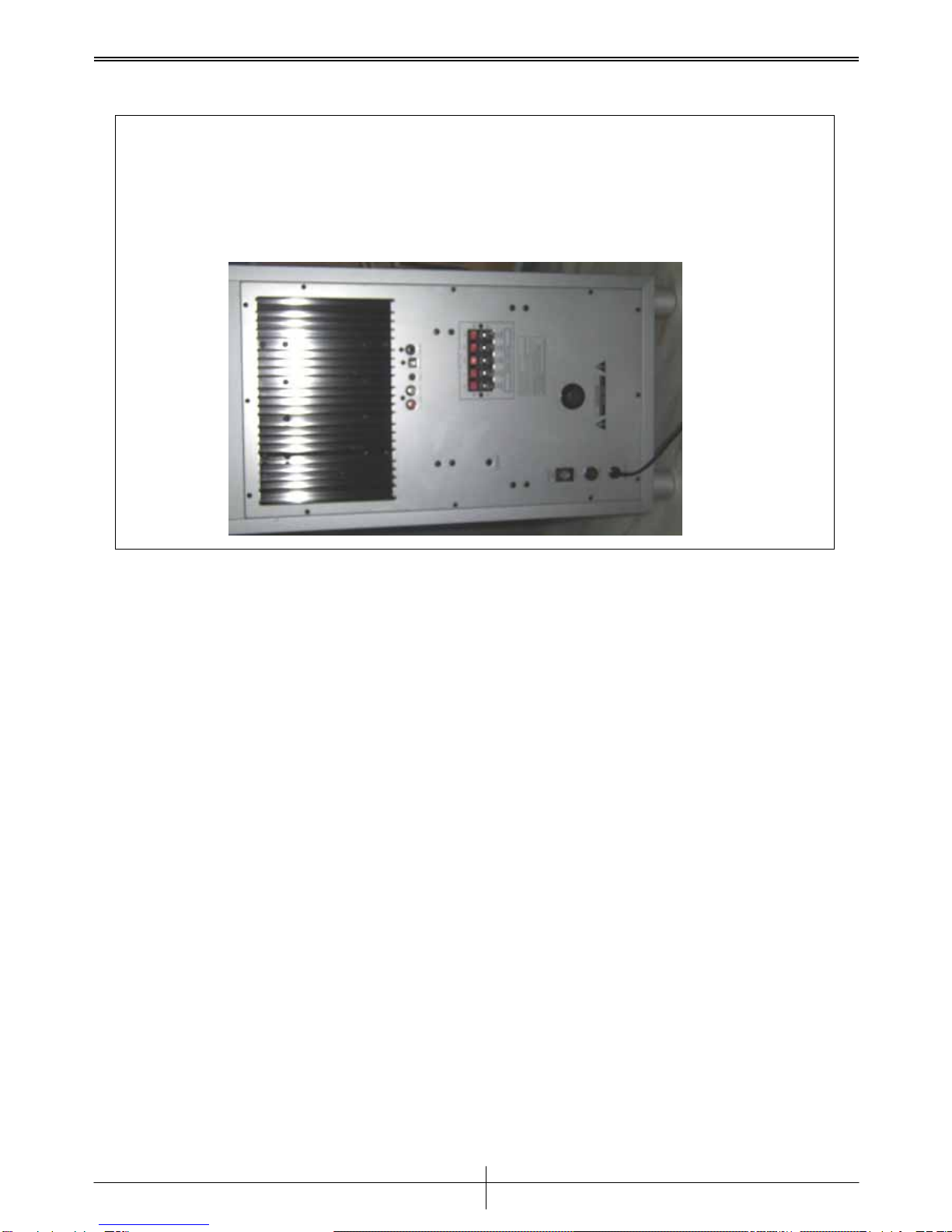
Disassemble & Assemble the Rear Cover....................................................................................5
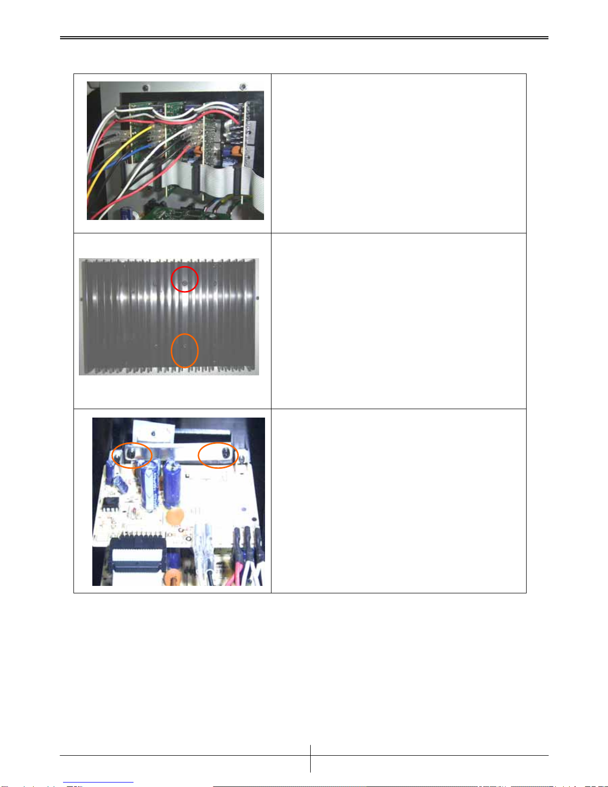
Disassemble & Assemble Amplifier PCBA (SUB)......................................................................6
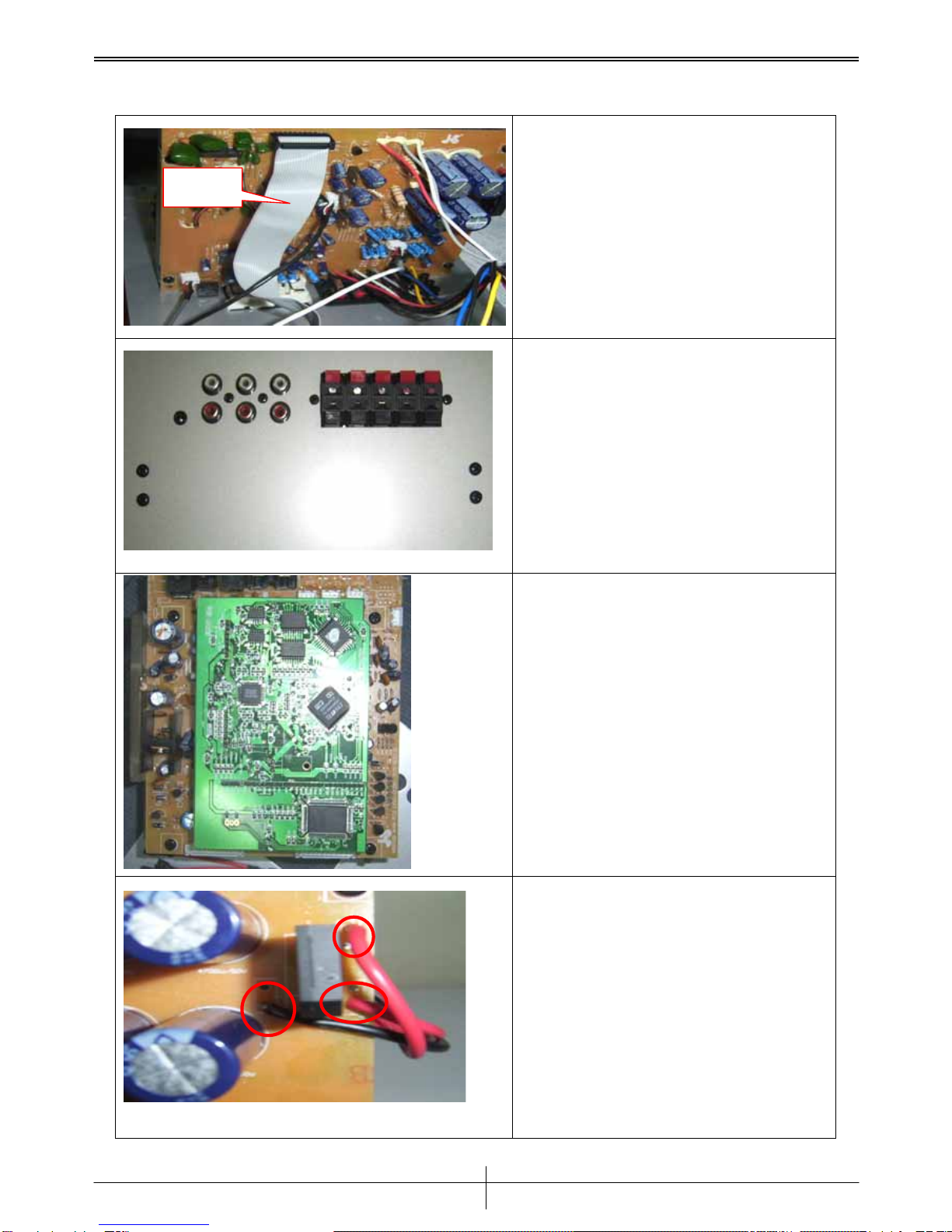
Disassemble & Assemble the Power Supply PCBA....................................................................7
Disassemble & Assemble the Decoder board..............................................................................9
Chapter 4. Testing Procedures ........................................................................................................10
Chapter 5. Important Notes.............................................................................................................11
Packing requirement for sending the PCB assembly.................................................................11
Short of spare parts while repairing a speaker...........................................................................11
Chapter 6. Parts list (Vender’s number)..........................................................................................12
Chapter 7. Tools..............................................................................................................................13
Version 1.0
P
age 1

ServiceManual
Chapter 1. INTRODUCTION
Function Block
Signal input
Front speakers
Subwoofer
Center speaker
AMP PCBA
POWER
PCBA
Rear speakers
Transformer
Main board
Decoder
PCBA
Version 1.0
P
age 2

ServiceManual
Chapter 2. Troubleshooting Guide
Problems Condition Probable Reasons Solutions
1.no power 1.power cable 1.cable broken 1.replace power cable
2.fuse 1.fuse broken 1.replace fuse
3.PCBA 1.center PCBA NG 1.replace center PCBA
2.power PCBA NG 1.replace power PCBA
3.Decoder PCBA NG 1.replace Decoder PCBA
2.display L.E.D. unlight 1.cover broken 1.L.E.D. broken or NG 1.replace L.E.D.
2.PCBA 1.Decoder PCBA NG 1.replace Decoder PCBA
2.cable broken 1.replace cable
3.button NG 1.button 1.button NG 1.replace button
2.PCBA 1.receiver NG 1.replace receiver
2.cable broken 1.replace cable
3.power PCBA NG 1.replace power PCBA
4.Decoder PCBA NG 1.replace Decoder PCBA
4.no sound 1.signal cable 1.signal cable NG 1.replace signal cable
2.PCBA 1.AMP PCBA NG 1.replace AMP PCBA
2.RCA socket NG 1.replace RCA socket
5.noise 1.speaker 1.speaker NG 1.replace speaker
2.PCBA 1.power PCBA NG 1.replace power PCBA
2.AMP PCBA NG 1.replace AMP PCBA
Version 1.0
P
age 3

ServiceManual
Chapter 3. Removal and Replacement
Disassemble & Assemble the Fuse
Step 1
Use a screwdriver to
turn counterclockwise
and open the fuse’s
cap.
Step 2
Get the Fuse and
replace it with the
same rate.
Step 3
To install the Fuse,
reverse the steps
shown above.
Fuse
Version 1.0
P
age 4

ServiceManual
Disassemble & Assemble the Rear Cover
Step 1
Using a screwdriver to loose 12 screws.
After taking all screws off, you can take up the Rear cover.
To install the rear cover, reverse the steps shown above.
C L
K
D
E
F
G
B
A
H
J
I
Version 1.0
P
age 5

ServiceManual
Disassemble & Assemble Amplifier PCBA (SUB)
Step 1
*Disassemble the Rear Cover first.
Disconnect the cables & wires
*Mark the position of cables & wires
Step 2
To loose 2 screws.(A & B)
Step 3
To loose 2 screws. After taking all screws
off, you can take up theAmplifier PCBA
*To install the Amplifier PCBA, reverse
the steps shown above.
A
B
Version 1.0
P
age
6

ServiceManual
Disassemble & Assemble the Power Supply PCBA
Step 1
*Disassemble the Rear Cover
first.
Disconnect the cable.
Step 2
To loose 8 screws. Form A-H.
Step 3
To loose 4 screws. Form I-L.
Step 4
Unsolder the wires on Power
Supply PCBA. And remove the
wires.
*Mark the position of wires
Cable
GH
E F
D
C
B
A
I K
J L
Version 1.0
P
age
7

ServiceManual
Step 5
Unsolder the wires on Power
Supply PCBA. And remove the
wires.
*Mark the position of wires
Step 6
Disconnect the 3 cables. *To
install the Power Supply PCBA,
reverse the steps shown above.
Red
Grey
White
Version 1.0
P
age 8

ServiceManual
Disassemble & Assemble the Decoder board
Step 1
Remove the main board.
Step 2
Use tweezers to remove the fixed
glue. And then use your hands to
separate decoder board from
main board.
*To install the decoder board,
reverse the steps shown above.
Version 1.0
P
age 9

ServiceManual
Chapter 4. Testing Procedures
Step 1
Connecting the GHT-511D to a DVD or VCD player. Play a DVD disk on it.
Step 2
Power on the GHT-511D. The monitor should display ‘321’then ‘0db’.
LED display ‘C’, ’L’, ’C’, ’SUB’, ’LS’, ’RS’, ’Digital’, ’Coaxial’, ’Lock’.
Step 3
Press the volume +/- button if it changes the volume level of each channel.
Step 4
Press the volume +/- button. Set the volume level to 0db.Change input signal to
‘Line’. The monitor should display ‘0db’.LED display ’SUB’, ’Line’, ’St’.
The sound only comes from L , R , SUB channel.
Step 5
Press the Mode button. LED display ’PL’, ’R’, ’C’,’SUB’, ’LS’, ’RS’, ‘Prologic’,
‘Line’, ’Lock’.
The sound comes from 5.1 channel.
Step 6
Press the Input button. Change input signal to ‘Optical’. The monitor should
display ‘321’then ‘0db’. LED display ’L’, ’R’, ’R’, ’C’,’SUB’, ’LS’, ’RS’,
‘Optical’, ’Lock’, ‘Digital’.The sound comes from 5.1 channel.
Step 7
Press the mute button it makes the volume level of each channel to null. Press the
Mute button again .It backs to normal.
Version 1.0
P
age 10

ServiceManual
Chapter 5. Important Notes
Packing requirement for sending the PCB assembly
PCB assembly is a kind of sophisticated electronic circuit board. Therefore, well packing will
be required when sending them by post or courier.
1. Some sophisticated IC components are mounted on the PCB assembly, hence it is
necessary to pack each PCB assembly with a separate static protecting beg, in order to
avoid static electricity.
2. Reliable external packing is also very important when sending the PCB assembly by post,
in that it would avoid unnecessarily lost or damage.
Short of spare parts while repairing a speaker
If you are short of spare parts when you have some speakers waiting to be repaired, it would be
recommended to take the necessary parts from one speaker, so that you may have the as many
as speakers be repaired and sent back to your customer, and left only one or few speakers
waiting for spare parts sending from KYE.
Version 1.0
P
age 11

ServiceManual
Chapter 6. Parts list (Vender’s number)
Item Part number description Position
1 J66-01236-000 PCBAAMP
2 J66-01236-400 PCBA CENTER AMP
3 J66-01335-000 PCBA POWER
4 J66-01335-010 PCBA VOLUME CONTROL
5 J83-005AA-U00 FUSE 125V/5A SLOW BLOW
6 J51-00002-03 NJM4558DD
7 J53-00001-02 Diode 1N4148
8 J51-01054-000 IC TDA7296 60W
9 J52-21001-000 Resonator 4MHZ
10 J51-01011-000 IC TL074/
11 J51-11018-000 IC L7815
12 J51-11019-000 IC L7915
13 J51-21006-010 IC PT2258
14 J52-00027-01 Transistor 2SC1815
15 J52-31003-000 FET 2SJ111
16 J53-21009-000 Diode KBU808
17 J51-11024-000 IC L7805CV/ST
18 J51-21002-300 MPU EM78P451P
19 J52-00026-02 Transistor 2SA1015
20 J66-01335-330 PCBA DSP
Version 1.0
P
age 12

ServiceManual
Chapter 7. Tools
1. VCD or DVD Player
2. MUSIC CD or DVD
1. Soldering-Iron (40W)
1. Tweezers
2. Screwdriver
3. Pliers
4. Multimeter
5. Glue-heater
Version 1.0
P
age 13
Table of contents
Other Genius Home Cinema Speakers manuals