GeoVision GV-HD-SDI User manual

GV-HD-SDI Camera
GV-SDI-BX100 User’s Manual
Before attempting to connect or operate this product,
please read these instructions carefully and save this manual for future use.

104B© 2012 GeoVision, Inc. All rights reserved.
105BUnder the copyright laws, this manual may not be copied, in whole or in part, without
the written consent of GeoVision.
106BEvery effort has been made to ensure that the information in this manual is accurate.
GeoVision, Inc. makes no expressed or implied warranty of any kind and assumes no
responsibility for errors or omissions. No liability is assumed for incidental or
consequential damages arising from the use of the information or products contained
herein. Features and specifications are subject to change without notice.
107BGeoVision, Inc.
108B9F, No. 246, Sec. 1, Neihu Rd.,
109BNeihu District, Taipei, Taiwan
110BTel: +886-2-8797-8377
111BFax: +886-2-8797-8335
112B0Hhttp://www.geovision.com.tw
113BTrademarks used in this manual: GeoVision, the GeoVision logo and GV series
products are trademarks of GeoVision, Inc. Windows and Windows XP are registered
trademarks of Microsoft Corporation.
114BJuly 2012

1
Contents
1. SAFETY PRECAUTIONS AND INSTALLATION CONSIDERATION......................... 2
2. INTRODUCTION ............................................................................................... 5
3. FEATURES ....................................................................................................... 6
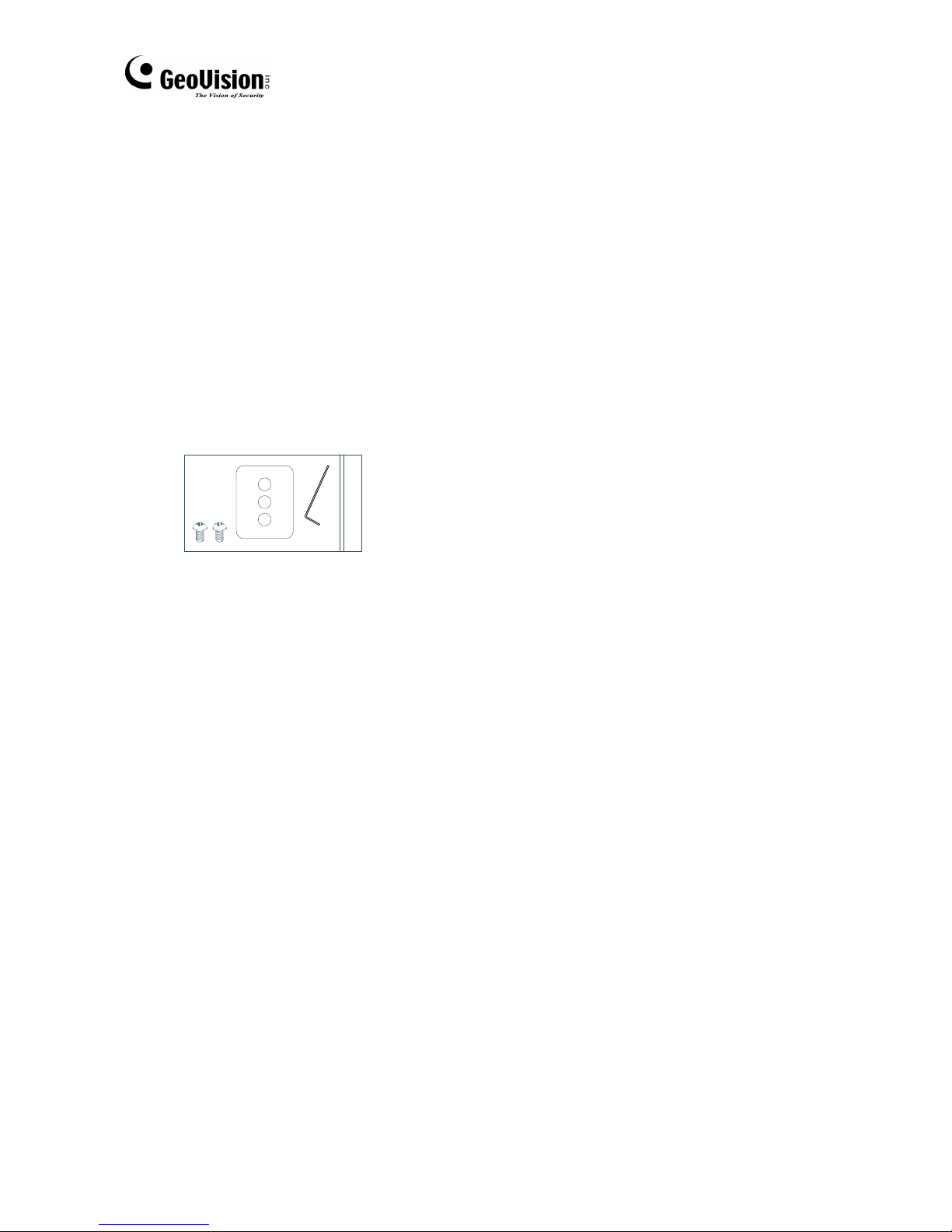
4. PACKING LIST................................................................................................... 8
5. NAME AND FUNCTION OF EACH PART ........................................................... 9
5.1 FRONT VIEW............................................................................................... 9
5.2 REAR VIEW................................................................................................11
6. INSTALLATION ................................................................................................ 13
6.1 LENS TYPE ............................................................................................... 13
6.2 USING AUTO IRIS LENS........................................................................... 13
6.3 USING A C/CS-MOUNT LENS................................................................... 14
6.3.1 INSTALLING A CS MOUNT LENS ................................................................. 14
6.4 CONNECT TO MONITOR.......................................................................... 16
6.5 CONNECT THE POWER........................................................................... 16
6.6 CONNECTION LAYOUT............................................................................ 17
6.6.1 CONNECTING THE KEYBOARD................................................................... 17
6.6.2 CONNECTING THE IR ILLUMINATOR .......................................................... 19
7. OPERATION..................................................................................................... 23
7.1 PELCO KEYBOARD (OR COMPATIBLE) OPERATION ............................ 23
8. SYSTEM SETUP .............................................................................................. 24
8.1 OSD (ON SCREEN DISPLAY)................................................................... 24
8.2 SUB MENU DESCRIPTION....................................................................... 25
8.2.1 CAMERA SETUP ............................................................................................ 25
8.2.2 EXPOSURE SETUP ....................................................................................... 25
8.2.3 DAY/NIGHT SETUP ........................................................................................ 26
8.2.4 WHITE BALANCE SETUP ............................................................................. 27
8.2.5 EFFECT SETUP ............................................................................................. 28
8.2.6 PRIVACY MASK SETUP ................................................................................ 28
8.2.7 DISPLAY INFO SETUP................................................................................... 30
8.2.8 COMMUNICATION SETUP ............................................................................ 32
8.2.9 DEFAULT SETUP ........................................................................................... 32
9. SPECIFICATIONS .......................................................................................... 33

2

Safety Precautions
3
1
1. Safety Precautions and Installation
Consideration
CAUTION
RISK OF ELECTRIC SHOCK.
DO NOT OPEN!
CAUTION :
TO REDUCE THE RISK OF ELECTRICAL SHOCK,
DO NOT OPEN COVERS (OR BACK).
NO USER SERVICEABLE PARTS INSIDE.
REFER SERVICING TO QUALIFIED
SERVICE PERSONNEL.
WARNING: Alert the user to the presence of un-insulated “dangerous voltage”.
CAUTION: Alert the user the presence of important operating and maintenance
(Servicing) instructions in the literature accompanying the appliance.
Disposal of Old Electrical & Electronic Equipment (Applicable in the
European Union and other European countries with separate collection
systems).
This symbol indicates that this product shall not be treated as household waste.
Instead it shall be handed over to the applicable collection point for the recycling of
electrical and electronic equipment. By ensuring this product is disposed of correctly,
you will help prevent potential negative consequences for the environment and human
health. For more detailed information about recycling of this product, please contact
your local city office, your household waste disposal service or the shop where you
purchased the product.
Please be extra careful not to shake the product.
Please avoid places where frequent vibrations or shocks.
Do not install the product in extreme temperature conditions.
Only use the camera under conditions where temperatures are between -10℃and +60℃. Be
especially careful to provide ventilation when operating under high temperatures.
It is advised to read the Safety Precaution Guide through carefully before
operating the product, to prevent any possible danger.

4
Do not install the product in an environment where the humidity is high.
Unless the product is waterproof or weatherproof, otherwise it can cause the image quality to
be poor.
Do not expose to strong light (sun rays), as color filters will be discolored.
Do not spill liquid of any kind on the product.
If it gets wet, wipe it dry immediately. Alcohol or beverage can contain minerals that corrode
the electronic components.
When any abnormal occurs, make sure to unplug the unit, and contact your local dealer.
Installation Consideration:
It is recommended to use RG-59 cable, with the maximum cable distance of 100
meters, to maintain a stable signal.

Introduction
5
2
2. Introduction
This HD-SDI digital image camera uses a high sensitive color Sony 1/2.8” interline
transfer Charge Coupled Device (CMOS) image sensor, producing pictures reaching
up 900 lines of horizontal resolution.
Super ATR-EX technology can achieve the WDR application through the normal
image sensor. The camera-side initiatively provides mobile detection warnings
offering more comprehensive monitoring of safety protection. Carefully planned
privacy zone enables monitoring more at ease.
There are two models of cameras:
Model No. Lens Description
GV-SDI-BX100-0 Varifocal 2 MP, D/N, Auto Iris
GV-SDI-BX100-1 Fixed 2 MP, D/N, Fixed Iris

6
3. Features
High Resolution
Excellent Sensitivity
CMOS Sensor provides high resolution
reaching up 900 TVL with advanced
and clear picture quality.
High sensitivity, low smear, high
anti-blooming and high S/N ratio
ATR-EX (WDR) Digital Noise Reduction (DNR)
High-quality ATR-EX (Augmenting Tone
Reproduction) or WDR (Wide Dynamic
Range). Functions perfectly show the
image details between dark and light.
Newly added environment dynamic
detection switch, enhancing image
efficiency.
2D DNR, realize the clear image at low
light environment, clear picture quality
saving hard disk storage size of DVR.
Day & Night Resolution Support
Mechanic IR cut-filter driving unit with
AE provides change from color to B&W
mode automatically for day and night
24-hour surveillance. Selectable
between manual Day & Night control
or from external input signal Day &
Night control.
Support 12 types of resolution and
Auto switch image output.
1080P60 ,1080P50 ,1080I60 ,
1080I50, 1080P30, 1080P25 ,
1080P59.94 , 1080P29.97 ,
1080I59.94 ,720P60, 720P50 ,
720P59.94.
Privacy Mask RS485 / RS422 Function
Privacy image masking with free
position supports up to 16 privacy
mask areas.
Support PELCO P/D protocol ,
RS485 / RS422 function output.

Features
7
3
Lens (C/CS Mount) Extra Connection
Support the auto-iris lens by DC type
(DC-Drive) or fixed iris lens.
Control the camera easily by
keyboard/PT Driver via RS485
interface.
OSD Image Control
OSD (On Screen Display) Setup Menu.
Camera title setup of up to 16
alphanumeric letters.
Performance: positive/ negative
image, mirror function (left/ right),
reverse turn (up/ down), and 180°
rotation.
Hotkey (Factory Default) Application
Press Up button for approximately 10
seconds after power-on, the camera will
be reset to its factory settings.
All functions can be operated from
OSD: AES (Automatic Electronic
Shutter), AI (Auto Iris), GC (Gain
Control), WB (White Balance) and BLC
(Back Light compensation).

8
4. Packing List
Check and make sure all the items shown below are included in your product
package. If something is missing, contact your dealer as soon as possible.
1. GV-HD-SDI Camera (with Varifocal or Fixed Megapixel Lens)
2. DC 12V Power Adapter
3. Accessories
•Screw x 2
•Mounting Tripod Base x 1
•L-wrench x 1
4. User’s Manual

Name and Function of Each Part
9
5
5. Name and Function of Each Part
5.1 Front View
GV-SDI-BX100-0 (Varifocal Lens)
23
14
○
1Focus Screw Adjusts the focus of the camera.
○
2Zoom Screw Adjusts the zoom of the camera.
○
3Auto Iris Connector Plug the iris control cable to the connector.
○
4Mounting Tripod Base Mounting base for installing the camera.

10
GV-SDI-BX100-1 (Fixed Lens)
2
1
3
○
1Focus Screw Adjusts the focus of the camera.
○
2Auto Iris Connector Not functional.
○
3Mounting Tripod Base Mounting base for installing the camera.

Name and Function of Each Part
11
5
5.2 Rear View
○
1Video-Out terminal: Sends video signal (HD-SDI) and connects to the
video input terminal of the monitor.
○
2Function Input/ Output and RS-485 Interface
(Protocol: AUTO/ NATIVE/ PELCO/ LG. Speed: 2.4K/ 4.8K/ 9.6K/ 115.2K BPS)
No. Name Function
1 DNI External Day/ Night input
2 GND Ground
3 DNO Day/ Night output
4 GND Ground
5 D+ R+ RS-422/ RS-485 Interface R+
6 D- R- RS-422/ RS-485 Interface R-
7 T+ RS-422/ RS-485 Interface T+
8 T- RS-422 RS-485 Interface T-
○
3Power LED: This lamp is lit when the camera is receiving power
normally.

12
○
4OSD Button:
No. Name Function
1 SUp (S)
2 TDown (T)
3 (+)/►Increase Value (+)
4 (-)/◄Decrease Value (-)
5 Menu Enter or Exit Setup Menu
•Up button: Used to move cursor up in the menu screen and to
zoom-in.
<Note>
Press Up button for approximately 10 seconds after
power-on, the camera will be reset to its factory
settings.
•Down button: Used to move cursor down in the menu screen and to
zoom-out.
•Right button: Used to move the cursor right in the menu screen and to
increase a setup value.
•Left button: Used to move the cursor left in the menu screen and to
decrease a setup value.
•Menu Button: Displays the menu on the screen and to enter or exit the
selection.
○
5Power input
terminal:
Connects to the appropriate power.

Installation
13
6
6. Installation
6.1 Lens Type
The camera is supplied with a CS-mount lens. You could refer to the below steps
only when changing lenses.
6.2 Using Auto Iris Lens
Fit the cover of the auto iris connector plug, remove the protective glass cover from
the front of the camera, and fasten the auto iris lens by turning it clockwise.
Auto Iris PIN definitions
Pin VIDEO DRIVER DC DRIVER
(Direct DRIVE)
1
2
3
4
VDC OUT
IRIS OUT
N.C.
GND
DAMP-
DAMP+
DRIVE+
DRIVE-
1. Fit the cover of the auto iris lens connector plug, remove the protective glass cover
from the front of the camera, and fasten the auto iris lens by turning it clockwise.

14
3. When a lens is mounted, adjustment of the back-focus may sometimes be
required. Adjust the lens focus ring when the correct focus cannot be obtained.
Back Focus Adjustment
(1) Fully open the aperture and set the focus ring to “⎟” (infinity).
(2) Loosen the two back-focus screws with L-wrench, and turn the lens mount to
focus.
(3) After adjusting the back-focus, tighten the back-focus screw.
6.3 Using a C/CS-Mount Lens
You can optionally change the lens on the camera. Before installing a lens, identify
the lens type first. (C-Mount or CS-Mount.)
6.3.1 Installing a CS Mount Lens
Remove the installed lens on the camera, and turn the CS-Mount Lens clockwise to
install it. And set focus of the camera by loosening the two back-focus screw with an
L-wrench.

Installation
15
6
6.3.2 Installing a C Mount Lens
Remove the installed lens on the camera, and turn the C-Mount Lens clockwise to
install it. And set focus of the camera by loosening the two back-focus screw with an
L-wrench.
<Note>
•C-mount adapter is not supplied with the camera.
•Use the lens connector shown in the following figure. If the dimensions of the
connector are incorrect, it may damage the camera, or the lens may not be
installed firmly.

16
6.4 Connect to Monitor
Connect the Video-out (HD-SDI) port on the rear panel of the camera to a monitor. As
the connecting method varies depending on the instrument, therefore refer to the
manual supplied with the instrument for more information.
6.5 Connect the Power
Since the camera supports both AC and DC, you may connect an AC 24V, 1000mA
adaptor or a DC 12V, 1000mA adaptor. There is no positive (+) and negative (-)
difference for the two power connectors.

Installation
17
6
6.6 Connection Layout
To connect the keyboard and IR illuminator, follow the instructions shown below:
6.6.1 Connecting the Keyboard
Connecting the IR illuminator

18
PELCO Keyboard (or compatible) Installation
RS-422 interface is used for communicating PELCO keyboard. Refer to Fig. 1;
connect R+ of the camera to T+ of the PELCO keyboard. Connect R- of the camera
to T- of the PELCO keyboard.
User could adjust Camera ID via rear panel keys or via remote commands. Protocol,
Speed and Parity should only be adjusted via rear panel keys.
Communication Setting
1 ~ 255 for P protocol
CAMERA ID 1 ~ 255 for D protocol
PROTOCOL PELCO
SPEED 2400, 4800, 9600, 115200
PARITY NONE
The speed of camera should be the same as the speed of the keyboard. Adjusted
function is only effective, after exiting the OSD setup menu.
<Note>
•Maximum cable distance for RS-485 communication over 24-gauge wire is 4,000
feet (1,219 m). Recommend using shielded twisted pair cable that meets the
basic requirements for EIA RS-485 applications.
Fig.1
Table of contents
Other GeoVision Camcorder manuals