German Physiks Emperor User manual

This product complies with European Union directive LVD 2014/35/EU,
ERP 2009/125/EG, EMC 2014/30/EU and RoHS 2011/65/EU
© German Physiks 2019
Revision e
Released 21st May, 2019
We reserve the right to change the information contained in this manual without notice. For the
latest version please see our web site at www.german-physiks.com
Emperor Extreme Integrated Amplifier
User Manual

2
SAFETY INSTRUCTIONS ..................................................................................................................................................... 3
SIMPLIFIED EU DECLARATION OF CONFORMITY ............................................................................................................. 6
1. INTRODUCTION ........................................................................................................................................................... 7
2. HOW TO USE THIS MANUAL ........................................................................................................................................ 7
3. UNPACKING YOUR AMPLIFIER ..................................................................................................................................... 7
4. POWER SUPPLY ............................................................................................................................................................ 8
5. LOCATION .................................................................................................................................................................... 8
6. FRONT PANEL CONTROLS AND FUNCTIONS ............................................................................................................... 9
7. REAR PANEL FEATURES AND FUNCTIONS ................................................................................................................. 10
8. USING THE AMPLIFIER IN A STANDARD SYSTEM ...................................................................................................... 12
9. USING THE AMPLIFIER IN A BI-WIRED SYSTEM ......................................................................................................... 14
10. USING THE AMPLIFIER IN A MULTI-AMPED SYSTEM .............................................................................................. 15
11. USING THE AMPLIFIER WITH AN ACTIVE CROSSOVER ............................................................................................ 19
12. REMOTE CONTROL .................................................................................................................................................. 24
13. AMPLIFIER BREAK-IN ............................................................................................................................................... 25
14. CARE OF YOUR AMPLIFIER ...................................................................................................................................... 25
15. FUSES ....................................................................................................................................................................... 25
16. WARRANTY .............................................................................................................................................................. 26
17. SERVICE AND SUPPORT ........................................................................................................................................... 26
18. DISPOSAL ................................................................................................................................................................. 27
19. HOW TO CONTACT US ............................................................................................................................................. 27
20. EMPEROR INTEGRATED AMPLIFIER SPECIFICATIONS ............................................................................................. 28
21. WARRANTY REGISTRATION ..................................................................................................................................... 29
TABLE OF CONTENTS

3
IMPORTANT SAFETY AND INSTALLATION INSTRUCTIONS
WARNING: Do not remove the product’s covers. This product contains no user serviceable parts.
WARNING: To reduce the risk of electric shock or fire, do not expose this product to rain or moisture.
The lightning flash with arrowhead symbol, within an equilateral triangle, is
intended to alert the user to the presence of an uninsulated "dangerous voltage"
within the product's enclosure that may be of sufficient magnitude to constitute a
risk of electric shock to persons.
The exclamation point within an equilateral triangle is intended to alert the user to
the presence of important operating and maintenance (servicing) instructions in
the literature accompanying the product.
SAFETY INSTRUCTIONS
WARNING: To prevent the risk of electric shock please carefully read and follow the instructions below.
1. Before attempting to use this product please read all of the safety and installation instructions and the
explanation of safety symbols in this manual
2. This product must be grounded. This reduces the risk of electric shock in the event of a malfunction.
This product is supplied with a power supply cable that incorporates a conductor to connect the equipment
to ground and a power plug that incorporates a grounding pin. The plug must be connected to a power
outlet that incorporates a ground connection and which has been properly installed and grounded in
accordance with all the appropriate regulations. If the power cable or plug shows any signs of damage,
please consult a qualified service technician.
DANGER: Incorrect connection of the equipment’s grounding can result in a serious risk of electric shock.
Under no circumstances should the cable or plug provided with this product be modified. If it will not fit in
the power outlet, contact your supplier for a power cable fitted with the appropriate plug, or have an
appropriate outlet installed by a qualified electrician.
NEVER use an adaptor that defeats the ground connection. This can have potentially fatal consequences.
If you have any doubt as to whether your product is properly grounded, please consult a qualified
electrician.
3. The product is designed solely for operation indoors in audio and video systems in domestic
environments.
4. Do not use this product in an environment that is damp or has a high relative humidity, or that is near
water, such as close to a bath tub, wash basin, kitchen sink, in a damp basement, or near a swimming pool
or other similar environment. Moisture can bypass the electrical insulation and pose a risk of lethal electric
shock.
5. This product in combination with loudspeakers may be capable of producing sound levels that could
cause permanent hearing loss. Do not operate at a high-volume level, or at a level that is uncomfortable.
If you experience any hearing loss or ringing in the ears, you should consult an audiologist.

4
6. Do not block the ventilation slots on the top and bottom of the product. If you are positioning the product
on top of a carpet, ensure that the carpet pile does not obstruct the ventilation slots on the bottom of the
product. If you are placing the product on a soft surface which will come closer to the underside of the unit
than the height of the feet, place a suitable flat, hard base under the product.
If you are placing the product in a cabinet, ensure that there is adequate ventilation.
7. Do not position the product near naked flames or other sources of heat such as radiators, heaters or
ovens.
Note that electric equipment, including some amplifiers, may heat up significantly during operation.
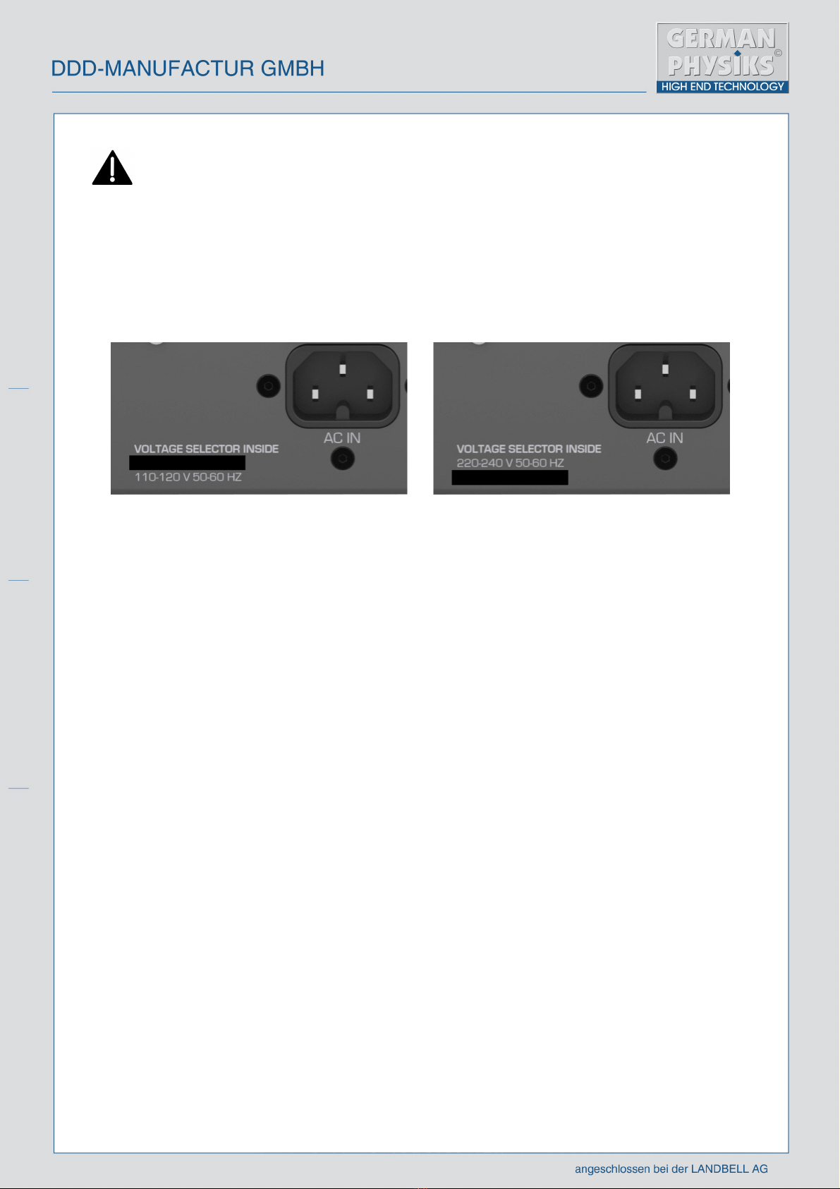
8. The product should only be connected to a power supply of the type shown on the product’s rear panel
by the power inlet.
9. If the product is to be left unused for a prolonged period of time, the power supply cable should be
removed from the outlet.
10. Always remove cables by holding the connector. Never pull or twist the cable itself.
11. When connecting cables always ensure that the connectors are of the appropriate type and are
properly aligned. Never use excessive force when inserting a plug into a socket. If a plug will not easily fit
into the socket, find out why.
12. Arrange the power cable in such a way that there is no risk of it being damaged e.g. by being stepped
on, by having anything placed on top of it, by someone tripping over it, having anything rolled over it, being
abraded by sharp edges or by being bent in an excessively tight radius. Failure to observe these
precautions may create the possibility of a fire risk and/or personal injury.
13. If the product is to be placed on a rack, stand or other supporting device, ensure that it is capable of
safely supporting the weight of the product.
14. Do not allow any liquids, or foreign objects to enter the product. If this happens, immediately switch
the product off and disconnect it from the power outlet, then contact qualified service personnel for
assistance.
15. Always unplug the unit from the wall outlet before cleaning. All that is required is a wipe with a dry
cloth or duster. Never use paint thinners or any other kind of solvent to clean this product. These constitute
a fire hazard and may also damage certain plastics.
16. If you notice an abnormal smell, or smoke coming from the product, immediately switch the product
off and disconnect it from the power outlet, then contact qualified service personnel for assistance.
17. In the event of any of the following occurring, you should seek the assistance of qualified service
personnel.
a. There is damage to the power supply cable or plug.
b. The product has been exposed to rain.
c. Objects have fallen on to the product, or liquid has been spilled and entered the product.
d. The product does not appear to be operating normally, or exhibits a marked change in
performance.
e. The product has been dropped or the enclosure has been damaged.

5
18. Extreme temperature fluctuations, high humidity and extended exposure to light can damage the
product and alter its appearance.
19. Observe the operating instructions of the equipment connected to this product.
20. Do not attempt to service the product beyond that described in this manual. All other servicing
should be referred to qualified service personnel.

6
SIMPLIFIED EU DECLARATION OF CONFORMITY
DDD Manufactur GmbH hereby declares that this equipment is in compliance with directive LVD
2014/35/EU, ERP 2009/125/EG, EMC 2014/30/EU and RoHS 2011/65/EU.

7
1. INTRODUCTION
Thank you for selecting the German Physiks Emperor Integrated amplifier. The Emperor Integrated
amplifier can deliver up to 600W RMS continuously into 4 ohms, which more than sufficient drive almost
any loudspeaker currently on the market. Balanced and unbalanced inputs are provided to allow it to be
connected to a wide range of sources. There are also two sets of outputs from the preamplifier section,
allowing the user to add up to 2 additional power amplifiers in order to set-up a tri-amped system.
The preamplifier and power amplifier sections can be split. This allows the amplifier to be used with an
active crossover such as the German Physiks DSP-X. The amplifier’s output stage then drives one section
of the loudspeaker and one or two extra stereo power amplifiers are used to drive the other sections,
depending on whether the loudspeaker is a 2-way or 3-way design.
Two 12V trigger outputs are provided. When these are connected to devices with compatible trigger inputs,
switching the Emperor Integrated amplifier on will automatically switch these units from standby mode to
on. Switching the Emperor Integrated amplifier off, will automatically switch these units back to standby
mode.
2. HOW TO USE THIS MANUAL
This manual is intended to give you all the information you need to safely install, connect, configure and
use the German Physiks Emperor Integrated amplifier.
Please read this manual carefully before attempting to install or use this product. Failure
to follow instructions in this manual may result in damage to the product which will not
be covered by the warranty.
Please keep this manual in a safe place so that you can refer to when necessary.
Please observe all warning notices on the product and in this manual. If you have not already done so,
please review the safety instructions on page 3 of this manual.
3. UNPACKING YOUR AMPLIFIER
The amplifier weighs approximately 65kg (143lbs). To avoid the risk of personal injury, it
must not be lifted by one person alone. Always have help when lifting the amplifier out of
the shipping carton.
Please keep all of the packing materials in case you need to ship the amplifier. If you need to ship the
amplifier, you must use the original shipping carton. The use of any other packing may result in the product
sustaining damage in transit. Such damage is not covered by the warranty. Replacement shipping cartons
may be obtained via your German Physiks dealer, national distributor, or directly from the factory.
After unpacking please confirm that you have the following items:
Item
Quantity
Description
1
1
Emperor Integrated amplifier
2
1
Leather case containing the user manual
3
1
Power lead
4
1
Cleaning cloth
5
1 pair
Direct input jumper cables
6
1 pair
Cotton gloves
If any of these items is missing please contact the supplier.

8
Check that the power lead supplied is fitted with a plug that matches the power outlet you
plan to use.
4. POWER SUPPLY
This product should only be connected to a power supply with a voltage included in the range indicated
on the back panel as shown below in figure 1. The actual format of the labelling may differ from the
picture below, but the meaning will be clear.
Ensure that the maximum power supply voltage does not exceed the upper limit of the operating voltage
range that the unit has been set for, otherwise serious damage may occur. If the voltage of the power
supply that you intend to use is not within the range indicated on the unit’s back panel, do not connect the
unit to the supply and consult your dealer.
5. LOCATION
The amplifier may be placed on a stand or shelf, provided it is safely able to support its weight.
It may also be placed directly onto the floor, provided that the ventilation slots on the underside of the
amplifier are not obstructed by a carpet or other floor covering. The clearance between the underside of
the amplifier and the floor covering should be the same as it would be if the amplifier was placed on a hard
surface. If necessary, find a means to raise the amplifier up to ensure the necessary clearance, or place
it on a flat base.
Do not place anything on top of the amplifier, as this may obstruct the ventilation slots on its upper surface.
Whilst the amplifier’s power supply has been designed to have a low external magnetic field, we
recommend that it is not sited close to sensitive items such as phono cartridges or phono stages.
Where ever the amplifier is located, allow a clearance of at least 5cm (3.5”) above the unit.
A clearance of at least 15cm (6”) should be allowed behind the amplifier so that cables may be routed
without the need to impose sharp bends.
Figure 1. Product operating power supply indication label.

9
6. FRONT PANEL CONTROLS AND FUNCTIONS
A. Source selector: Rotate this to select the desired input.
B. Power indicator: Indicates that power is connected to the amplifier.
C. Remote control receiver window: Do not obstruct this, otherwise operation of the remote control
may be impaired.
D. Direct input selection switch: When the amplifier has been put into Direct Input mode by pressing
the Direct Input button on the rear panel, the input to the output stage is disconnected from the
preamplifier section and the user can connect directly to the input of the output stage via the rear panel
DIRECT IN BAL and DIRECT IN UNBAL connectors. The Direct Input switch allows the user to
select which of these two inputs is used.
E. Gain selector switch: This only has effect when the unit is in the Direct Input mode. Pressing this
button cycles the unit through the three gain settings. Each setting has a slightly different voicing,
which allows the user to adjust the character of their system. When the Gain button is pressed, the
display will show the word GAIN for about 3 seconds, then the gain in dB, followed by the voicing.
Successive presses will select the next gain setting. These are shown in the table below.
Gain
Voicing
0dB
Neutral
-9dB
Warm
+3db
Analytical
To use function this in a standard set up requires that the supplied two balanced jumper cables are
fitted between the preamplifier output and the power section input. See section 7 for full instructions.
A
B
C
E
H
G
F
I
D
Figure 2. Emperor Integrated Amplifier front panel.

10
To avoid sudden jumps in volume that may damage your loudspeakers, always reduce the
amplifier’s volume setting to minimum before changing the gain setting.
F. Ground lift switch: This disconnects the amplifier’s signal ground from the chassis safety ground
and is useful in eliminating hum when this is caused by a ground loop. This is where there is more
than one ground connection between two pieces of audio equipment, thus forming a loop. This can act
as a single turn coil and stray magnetic fields from nearby equipment and/or power cables can induce
a mains frequency current in this loop, which then produces a hum that is heard from the loudspeakers.
If this is the cause of hum in a system, using the ground lift switch to break this loop will stop the hum.
G. Display brightness button: Successive presses of this button cause the display brightness to
repeatedly step from maximum to minimum, to off. If the display has been switched off, it will come on
for a few seconds when another control is used.
H. On switch: Wakes the unit from standby into normal operation and visa versa.
I. Volume control: Rotating the control clockwise will increase the volume level and rotating it counter-
clockwise will reduce the volume level. After switching the unit on and before playing music, always
check that the volume control has been set to a safe level. Failure to do this may result in the music
being unexpectedly loud, which in extreme cases may damage your loudspeakers.
7. REAR PANEL FEATURES AND FUNCTIONS
The signal input, output and loudspeaker terminals shown are for the right channel. The connectors for
the left channel are arranged in a mirror image of the right channel and are easy to identify.
J. Unbalanced input connectors: Connect to sources having unbalanced outputs.
K. Unbalanced Direct Input connector: Used to connect directly to the power amplifier section input.
To use this the Direct Input function must be enabled by pressing the Direct In button, figure 3, O.
L. Balanced Direct Input connector: Used to connect directly to the power amplifier section input.
To use this the Direct Input function must be enabled by pressing the Direct In button, figure 3, O.
NEVER make or break connections to either of the Direct Inputs when the amplifier is
switched on. Failure to observe this precaution could result in damage to the amplifier
and your loudspeakers.
Figure 3. Emperor Integrated Amplifier rear panel.
J
K
L
M
N
O
P
Q
R
S
V
U
T

11
NEVER make or break connections to any amplifier when it is switched on. Failure to
observe this precaution could result in damage to the amplifier and your loudspeakers.
M. Balanced input connectors: Connect to sources having balanced outputs. If a source has both
balanced and unbalanced outputs, we recommend that the balanced input is used as this will usually
produce superior results.
N. 12V trigger output. When connected to another device that has a compatible input, switching the
Emperor Integrated amplifier on, will automatically switch this unit from standby mode to on. Switching
the Emperor Integrated amplifier off, will automatically switch this unit back to standby mode. This is most
often used in home theatre systems to control projectors and motorised screens, where, due to their
location, easy access to their power switches may not be available.
O. Direct In switch: Puts the amplifier into Direct In mode, isolating the preamplifiers and power amplifier
sections and allowing direct connection to the power amplifiers section. The switch will light up when the
amplifier is in Direct In mode. This will also be indicated in the display.
P. 12V trigger output. When connected to another device that has a compatible input, switching the
Emperor Integrated amplifier on, will automatically switch this unit from standby mode to on. Switching
the Emperor Integrated amplifier off, will automatically switch this unit back to standby mode.
Q. Preamplifier section unbalanced outputs: Provides an output from the preamplifier section allowing
up to two more power amplifiers to be connected so that a tri-amped system may be set-up.
R. Loudspeaker output terminals: Connect to your loudspeakers.
S. Preamplifier section balanced outputs: Provides an output from the preamplifier section allowing
up to two more power amplifiers to be connected so that the tri-amped system can be set-up.
T. Power supply label: Shows which power supply voltage range the unit has been set for.
If this does not cover the voltage of the power supply you plan to use, do not attempt to
use the amplifier and consult your dealer.
U. Power inlet: Insert the power cable here.
V. Power switch: This is the main power switch. When installing the unit, this should be in the off position
as shown in figure 3.

12
8. USING THE AMPLIFIER IN A STANDARD SYSTEM
This section describes how to connect and set up the Emperor Integrated amplifier for use in a standard
2-channel system with passive loudspeakers as shown in figure 4.
We have also assumed that this is an established system and the only thing being changed is the
integrated amplifier. If any other components in the system are also being changed, please refer to the
user manual(s) of the item(s) concerned for guidance.
1. Ensure that all equipment in the system is switched off.
NEVER make or break connections to any amplifier when it is switched on. Failure to
observe this precaution could result in damage to the amplifier and your loudspeakers.
2. Connect right channel output of your main source to either, one of the amplifier’s right channel
unbalanced inputs (figure 3, J), or one of its right channel balanced inputs (figure 3, M). Where possible,
we recommend that you use the balanced inputs for your main sources, as this will usually produce
superior results.
Connect the left channel output of this source to the matching left channel input of the amplifier – for
example, if you have used the right channel unbalanced #2 input, you must also use the left channel
unbalanced #2 input.
Repeat this procedure with the remaining sources.
Make sure that all the plugs are pushed fully home into their sockets and that the left and right channels
for each source are not accidentally swapped over.
Try to arrange for the input cables to be separated as much as possible from where power cables will run.
This will reduce the chance of hum and other mains borne noise being picked up by the inputs.
3. Connect the right channel loudspeaker cables to the amplifier’s right channel loudspeaker terminals,
figure 3, R.
Ensure that that the loudspeaker’s +ve terminal is connected to the amplifier’s +ve loudspeaker terminal
and that the loudspeaker’s -ve terminal is connected to the amplifier’s -ve loudspeaker terminal.
Repeat the process for the left channel.
These terminals will accept both banana plugs and spade terminals. Where possible we recommend that
cables fitted with spade terminals are used, as this gives a superior connection.
If using banana plugs, ensure that each plug is pushed fully home into the hole in the centre of the terminal.
Figure 4. Standard 2-channel system.
German Physiks Emperor Integrated Amplifier
Music Source

13
If using spade terminals, loosen the loudspeaker terminal cap by turning it anti-clockwise a few turns to
allow the spade to be inserted so that it is pushed up against the centre of the terminal, then tighten the
terminal cap so that the spade is securely held.
Only tighten the terminal by hand. Never use any sort of tool, as this may result in damage to the terminal.
Arrange the loudspeaker cables so that they lie smoothly without any sharp bends or kinks. Also take care
that the cables are not stressed where they are joined to the terminations (banana plugs or spade terminals
depending on which type has been used).
4. Switch on your music source and allow it to stabilise. Do not start it playing yet.
5. Confirm that the rear panel power switch, figure 3, V, is in the off position, then connect the power cable
to the rear panel power inlet, figure 3, U, ensuring that it has been pushed fully home. Plug the other end
into the power outlet on the wall, or the power extension block that you are using. If this has a switch,
switch this on.
6. Switch on the power switch on the amplifier’s rear panel, figure 3, V. The front panel power indicator,
figure 2, B should come on. The unit is now in standby mode. Do not switch it on yet.
7. If you wish to use the Gain control on the amplifier’s front panel, figure 2, E, so that the amplifier’s gain
can be adjusted, you will need to fit the two short, balanced jumper cables supplied with the unit. Otherwise
go to step 10.
8. Fit one of the balanced jumper cables supplied with the unit between the right channel preamplifier
section balanced output, figure 3, S, and the right channel power amplifier section balanced input, figure
3, L.
9. Repeat the above step for the left channel.
10. Switch the amplifier on by pressing the front panel On button, figure 2, H. Allow 30 seconds for the
amplifier to stabilise.
11. Rotate the Volume control, figure 2, I, anti-clockwise and set the volume to minimum.
12. If you do not wish to use the Gain control and have not connected the preamplifier section to power
amplifier section jumpers as described in steps 8 and 9 above, go to step 15. The amplifier will default to
the nominal gain setting with a neutral voicing.
13. If you wish to use the Gain control on the amplifier’s front panel, the Direct In mode must be selected.
Check the front panel display. If it shows DIRECT IN ON, then the Direct In mode is already selected
and you can go to the next step.
If the display shows DIRECT IN OFF, press the rear panel Direct In button, figure 3, O. This will light
up to show that the Direct In mode has been selected. The front panel display will also show DIRECT
IN ON.
14. If the front panel display shows EXTERN INPUT XLR, then the power amplifier section XLR inputs
are already selected and you can go to the next step. Otherwise, press the front panel Input button, figure
2, D, so that the display shows EXTERN INPUT XLR

14
15. Rotate the Source control, figure 2, A, to select the input connected to the source that you are going
to use.
If you are not using the Gain control go to step 17.
16. If you have followed steps 8, 9, 13 and 14 above to set-up the Direct In mode, you will be able to use
the Gain control.
We recommend that initially the amplifier gain be set to 0dB (standard setting). This gives the amplifier a
neutral voicing.
Press the Gain button, figure 2, E, on the amplifier’s front panel once. The display will show the word
GAIN for about 3 seconds, followed by the current gain setting in dB and the voicing of that setting. Press
the GAIN button again as necessary until the gain is set to 0dB.
The voicing for the current gain setting is always shown in the top right hand corner of the default display.
To avoid sudden jumps in volume that may damage your loudspeakers, always reduce the
amplifier’s volume setting to minimum before changing the gain setting.
17. Start the music source playing, then slowly turn the Volume control clockwise until a comfortable
listening level is achieved.
We suggest that you experiment with the gain settings to find the one that produces the sound most to
your taste. To avoid sudden jumps in volume, always reduce the preamplifier volume setting to minimum
before changing the amplifier gain setting. As the amplifier’s sound may change during the first few days
of use as it settles down, we recommend that you listen to the gain settings again after this to confirm that
you have found the one you like best.
9. USING THE AMPLIFIER IN A BI-WIRED SYSTEM
If a loudspeaker can be bi-wired, it will have a separate set of input terminals for each section of its
crossover: one set for the tweeter section and one set for the bass/mid-section. To bi-wire such a
loudspeaker, you simply use a separate loudspeaker cable to connect each section of the crossover to the
amplifier. To make this easy, the Emperor Integrated amplifier has two sets of loudspeaker terminals for
each channel.
Bi-wiring can produce a useful improvement in sound quality, but bearing in mind the potential cost of an
extra set of loudspeaker cables, we recommend that the user borrows some extra cables first to see how
well this works with their loudspeakers. They can then decide if the improvement justifies the cost.

15
10. USING THE AMPLIFIER IN A MULTI-AMPED SYSTEM
In a multi-amped system, each section of the loudspeaker is driven by a separate power amplifier. This is
only possible if the loudspeaker has separate input terminals for each section of its crossover. Figure 5
show how a system with a 3-way loudspeaker would be configured for multi-amping. For clarity, only one
loudspeaker is shown. With a 2-way loudspeaker, only one additional power amplifier per channel would
be needed.
We have shown stereo power amplifiers in our illustration, in this case the German Physiks Emperor Stereo
power amplifier. This will work particularly well, as its power section is exactly the same as that used in
the German Physiks Emperor Integrated amplifier, so the gains are the same and they are matched tonally.
You could use other makers’ stereo or mono power amplifiers, providing they all had the same gain as the
Emperor Integrated amplifier.
Connecting the system
NEVER make or break connections to any amplifier when it is switched on. Failure to
observe this precaution could result in damage to the amplifier and your loudspeakers.
1. Set the equipment shown in figure 5 in the locations where they are to be used, paying attention the
ability of any supports used to be able to carry the loads imposed, cautions regarding not blocking cooling
vents and the other safety precautions mentioned at the start of this manual.
2. Ensure that all equipment in the system is switched off.
Figure 5. Multi-amped system.
Figure 4. Multi-amped system.
Input
Input
High
frequency
driver
German Physiks Emperor Stereo Amplifier
German Physiks Emperor Integrated Amplifier
Pre output
Mid
frequency
driver
Low
frequency
driver

16
3. Connect right channel output of your main source to either, one of the amplifier’s right channel
unbalanced inputs (figure 3, J), or one of its right channel balanced inputs (figure 3, M). Where possible,
we recommend that you use the balanced inputs for your main sources, as this will usually produce
superior results.
Connect the left channel output of this source to the matching left channel input of the amplifier – for
example, if you have used the right channel unbalanced #2 input, you must also use the left channel
unbalanced #2 input.
Repeat this procedure with the remaining sources.
Make sure that all the plugs are pushed fully home into their sockets and that the left and right channels
for each source are not accidentally swapped over.
Try to arrange for the input cables to be separated as much as possible from where power cables will run.
This will reduce the chance of hum and other mains borne noise being picked up by the inputs.
4. Connect loudspeaker cables between the right channel high-frequency crossover input and the
amplifier’s right channel loudspeaker terminals, figure 3, R.
Ensure that that the loudspeaker’s +ve terminal is connected to the amplifier’s +ve loudspeaker terminal
and that the loudspeaker’s -ve terminal is connected to the amplifier’s -ve loudspeaker terminal.
Repeat the process for the left channel high-frequency crossover input.
These terminals will accept both banana plugs and spade terminals. Where possible we recommend that
cables fitted with spade terminals are used, as this gives a superior connection.
If using banana plugs, ensure that each plug is pushed fully home into the hole in the centre of the terminal.
If using spade terminals, loosen the loudspeaker terminal cap by turning it anti-clockwise a few turns to
allow the spade to be inserted so that it is pushed up against the centre of the terminal, then tighten the
terminal cap so that the spade is securely held.
Only tighten the terminal by hand. Never use any sort of tool, as this may result in damage to the terminal.
Arrange the loudspeaker cables so that they lie smoothly without any sharp bends or kinks. Also take care
that the cables are not stressed where they are joined to the terminations (banana plugs or spade terminals
depending on which type has been used).
4. Connect the loudspeakers’ mid-frequency crossover inputs and low-frequency crossover inputs to the
loudspeaker terminals on their associated power amplifiers. In each case, ensure that that the crossovers’
+ve terminals are connected to the amplifiers’ +ve loudspeaker terminals and that the crossovers’ -ve
terminals are connected to the amplifiers’ -ve loudspeaker terminals.
Take care not to mix up the left and right channels.
6. Connect the amplifier’s right channel preamplifier section outputs, figure 3 Q or S, to the right channel
inputs of the other power amplifiers. We recommend that you use the balanced outputs.
7. Connect the amplifier’s left channel preamplifier section outputs, to the left channel inputs of the other
power amplifiers. Use the same interface, unbalanced or balanced, as you use in step 5.
8. Confirm that the main power switches on all the amplifiers are off.
9. Connect power cables to each amplifier, ensuring that they are pushed fully home into their respective
inlets.

17
10. Switch on your music source and allow it to stabilise. Do not start it playing yet.
11. Connect the amplifier power cables to the power outlets on the wall or extension block and confirm
that these are all switched on.
12. Switch on the power switch on the integrated amplifier’s rear panel, figure 3, V. The front panel power
indicator, figure 2, B should come on. The unit is now in standby mode. Do not switch it on yet.
13. If you wish to use the Gain control on the amplifier’s front panel, figure 2, E, so that the amplifier’s
gain can be adjusted, you will need to fit the two short, balanced jumper cables supplied with the unit.
Otherwise go to step 16.
14. Fit one of the balanced jumper cables supplied with the unit between the right channel preamplifier
section balanced output, figure 3, S, and the right channel power amplifier section balanced input, figure
3, L.
15. Repeat the above step for the left channel.
16. Switch the amplifier on by pressing the front panel On button, figure 2, H. Allow 30 seconds for the
amplifier to stabilise.
17. Rotate the Volume control, figure 2, I, anti-clockwise and set the volume to minimum.
18. If you do not wish to use the Gain control and have not connected the preamplifier section to power
amplifier section jumpers as described in steps 14 and 15 above, go to step 21. The amplifier will default
to the nominal gain setting with a neutral voicing.
19. If you wish to use the Gain control on the amplifier’s front panel, the Direct In mode must be selected.
Check the front panel display. If it shows DIRECT IN ON, then the Direct In mode is already selected
and you can go to the next step.
If the display shows DIRECT IN OFF, press the rear panel Direct In button, figure 3, O. This will light
up to show that the Direct In mode has been selected. The front panel display will also show DIRECT
IN ON.
20. If the front panel display shows EXTERN INPUT XLR, then the power amplifier section XLR inputs
are already selected and you can go to the next step. Otherwise, press the front panel Input button, figure
2, D, so that the display shows EXTERN INPUT XLR
21. Rotate the Source control, figure 2, A, to select the input connected to the source that you are going
to use.
If you are not using the Gain control go to step 23.
22. If you have followed steps 14, 15, 19 and 20 above to set-up the Direct In mode, you will be able to
use the Gain control.
We recommend that initially the amplifier gain be set to 0dB (standard setting). This gives the amplifier a
neutral voicing.
Press the Gain button, figure 2, E, on the amplifier’s front panel once. The display will show the word
GAIN for about 3 seconds, followed by the current gain setting in dB and the voicing of that setting. Press
the GAIN button again as necessary until the gain is set to 0dB.
The voicing for the current gain setting is always shown in the top right hand corner of the default display.

18
To avoid sudden jumps in volume that may damage your loudspeakers, always reduce the
amplifier’s volume setting to minimum before changing the gain setting.
23. Switch on the rear panel mains switches on the other two amplifiers and then press their front panel
On buttons. Allow 30 seconds for the units to stabilise.
If you are using another maker’s power amplifiers, follow the start-up procedure in the maker’s user
manual.
24. If you are using German Physiks power amplifiers, follow the procedure above to set their gains to the
same as that selected for the integrated amplifier, which at this stage should be 0dB.
If you are using another maker’s power amplifiers, their gains must be set to be the same as that of the
integrated amplifier. Refer to the user manual for instructions. Check whether the amplifier should be
switched off when the gain is changed. You may have to adjust the integrated amplifier’s gain setting to
match the power amplifiers. Failure to set the same gain on all amplifiers will result in a serious frequency
imbalance
25. Start the music source playing, then slowly turn the Volume control clockwise until a comfortable
listening level is achieved.
We suggest that you experiment with the gain settings to find the one that produces the sound most to
your taste. To avoid sudden jumps in volume, always reduce the preamplifier volume setting to minimum
before changing the amplifier gain setting. As the amplifier’s sound may change during the first few days
of use as it settles down, we recommend that you listen to the gain settings again after this to confirm that
you have found the one you like best.

19
11. USING THE AMPLIFIER WITH AN ACTIVE CROSSOVER
This section describes how to connect and set up the Emperor Integrated amplifier in a fully active system.
This is where the audio signal is split into the bands required by each section of the loudspeaker at low
level using an active crossover. Each band is then fed to a separate power amplifier to drive its section of
the loudspeaker. The loudspeaker has no internal passive crossover and its drivers are connected directly
to its input terminals.
In this example we are illustrating how a system with a 3-way loudspeaker would be configured – figure 6.
With a 2-way loudspeaker only one additional power amplifier per channel would be needed.
We have shown the German Physiks Emperor DSP-X active crossover in our illustration, however any 3-
way active crossover could be used, though with not necessarily such good results! One of the many
advantages of the Emperor DSP-X is that if it is to be used with a set of German Physiks loudspeakers, it
will be shipped pre-configured for the model concerned. The user then simply has to connect it into the
system and switch it on.
We have also shown stereo power amplifiers in our illustration, in this case the German Physiks Emperor
Stereo Power amplifier. This will work particularly, well as its power section is exactly the same as that
used in the German Physiks Emperor Integrated amplifier, so the gains are the same and they are matched
tonally. You could use other makers’ stereo or mono power amplifiers, provided that they all had the same
gain as the Emperor Integrated amplifier.
For clarity, the connections for only one loudspeaker are shown in figure 6.
What are the advantages of an active system?
Although an active system is much more complex and therefore more expensive than a passive system, it
offers several advantages, which are especially useful in very high-end systems.
1. There is usually very little scope to adjust the frequency characteristics of a passive crossover to
compensate for variations in frequency response caused by individual room acoustics. The Emperor DSP-
X provides two means of adjustment to enable a more even frequency response to be achieved. The
relative levels of the 3 output sections may be adjusted via a front panel control and more sophisticated
adjustments may be made using a remote-control application.
2. In an active system, the elimination of the passive crossover allows the power amplifiers to be connected
directly to the drivers. This greatly improves the damping of the driver movement. This principally affects
the low frequency drivers, significantly improving the clarity of the bass.
3. Resistive components in a passive crossover dissipate power. Eliminating these improve both the
efficiency and the dynamic response of the system. More power can reach the drivers and the amplifiers
work with more headroom.
4. The use of a digital filter allows the loudspeaker designer to get much closer the exact filter characteristic
that they wanted, without having to accept the compromises imposed by the limitations of passive designs.
5. If a passive crossover is driven at high levels for a prolonged period, it can result in the resistive
components heating up sufficiently for their values to change and have an effect on the crossover’s
characteristics. Whilst this is usually a minor effect, the Emperor DSP-X eliminates the possibility of this
occurring.
In our experience, with a very high-end system where changes are more easily heard, the improvement in
sound quality, especially in the areas of bass clarity and overall transparency that the Emperor DSP-X
crossover provides, would be difficult to achieve by other means. This improvement is enhanced by the
Emperor DSP-X’s equalisation adjustment features.

20
Figure 6. Using the Emperor integrated amplifier with an active crossover
Other manuals for Emperor
1
This manual suits for next models
1
Table of contents
Other German Physiks Amplifier manuals
Popular Amplifier manuals by other brands

Lindsay Broadband
Lindsay Broadband LHA35RM installation manual

Hypex Electronics
Hypex Electronics UcD400 Stereo kit Getting started

Traynor
Traynor YS1082 instruction manual

Classe Audio
Classe Audio Delta MONO owner's manual

SNAP
SNAP Episode engineered EA-MINI-2D-35 Control protocol

AMC
AMC 2100 Instructions for installation and operation