Welcome!
G.M.Corporation Ltd is a manufacturer and distributor
headquartered in Seoul, Korea and founded in 1996.
The company offers a wide range of PC cases, Power
supplies, Computer peripheral and service to
customers worldwide.
It is G.M.Corporation’s mission to be the best provider
of the state-of-the-art products in the global market.
By offering superior products and complete service,
the company seeks to share the enjoyable computer
life for worldwide end users.
Through the constant invention and innovation,
G.M.Corporation has achieved a number of patents
for its products. As a result of being acknowledged
for sincere effort in research and development,
G.M.Corporation received a good venture company
certification from the Korean Business Administration
in 2001.
G.M.Corporation produces middle tower PC cases
and HTPC cases (Home Theater PC) which supports
mATX and ATX form factors. Our HTPC has a
fantastic design and functions and supports up to MS
Windows VISTA and MCE (Media Center Edition).
In an ever-changing business environment,
G.M.Corporation continues to be committed to
customer satisfaction with high quality and innovative
design. G.M.Corporation is devoted to develop
superior goods and become a leading computer case
supplier in Korea.
Thank you for your concern and support.
Contents
Chapter 1. Product Introduction
1.1 Specification
1.2 Features & Benefit
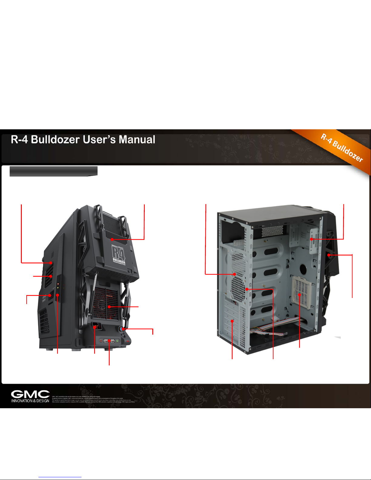
1.3 Case Overview
Chapter 2. Installation
2.1 Side Panel Removal
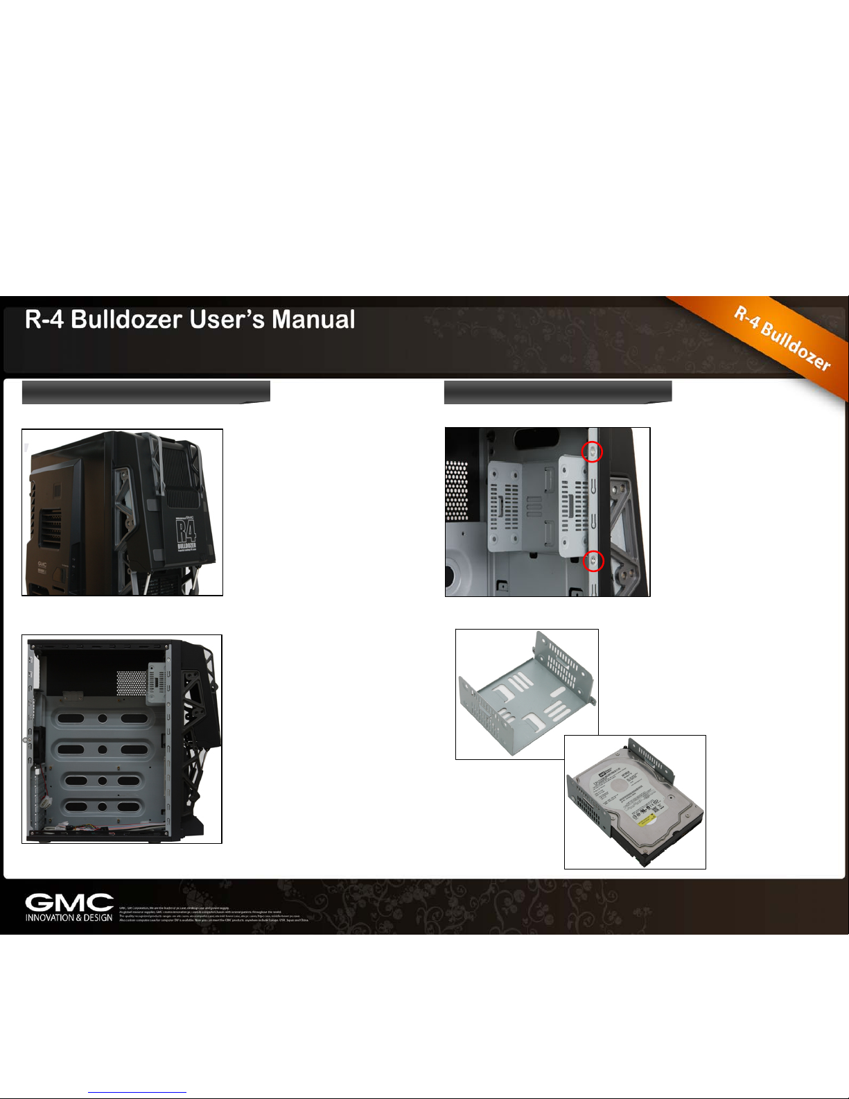
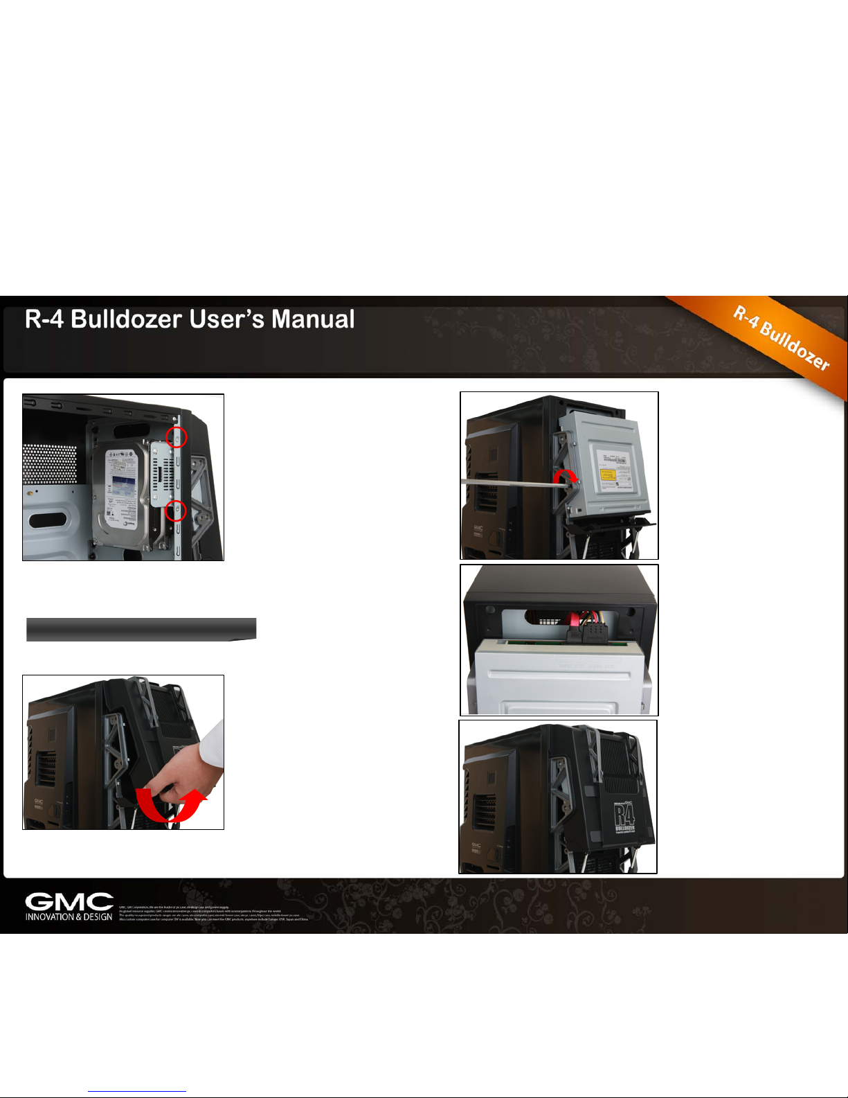
2.2 HDD Installation
2.3 ODD Installation
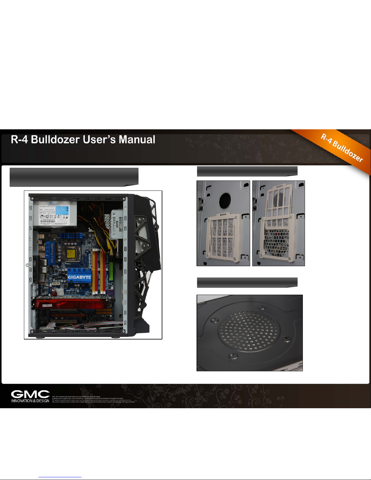
2.4 Power Supply, M/B, Graphic Card Installation
2.5 Air Filter
2.6 Bottom Fan Hole
2.7 Case LED & Switch Connections
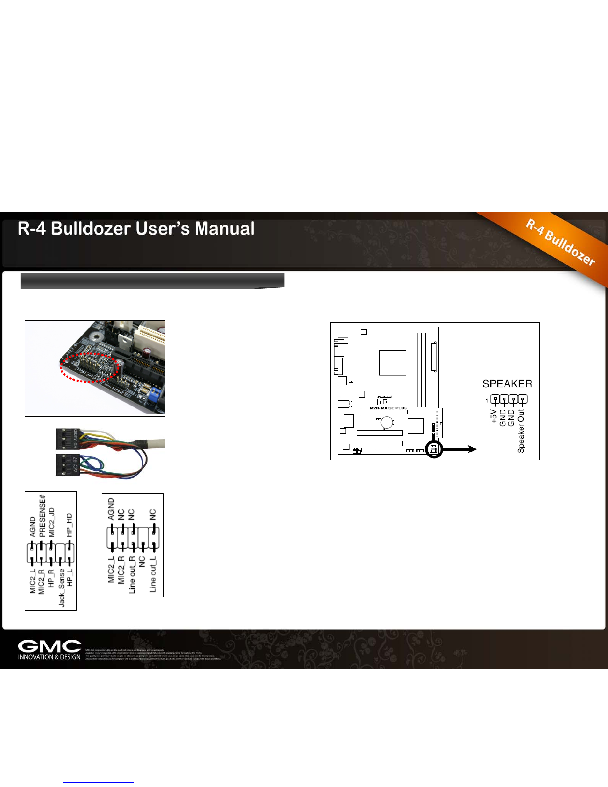
2.8 Connecting FPIO to Mainboard
2.9 Front thermometer power cable connection
2.10 Side thermometer power cable connection
2.11 Side fan cable connection


 user manual")


