GraceWood Little Gracie II User manual

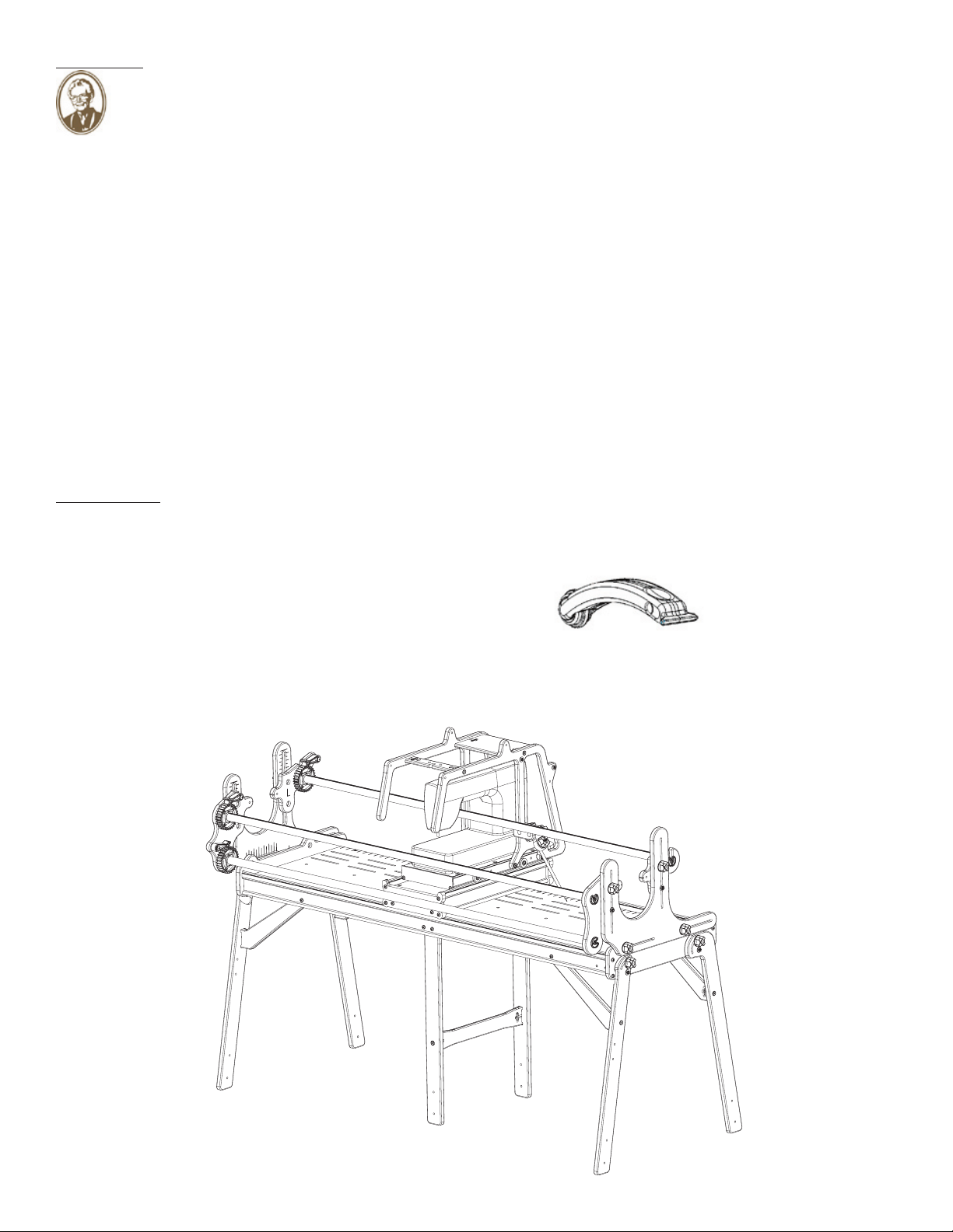
The New Little Gracie II
Home Machine Quilting System
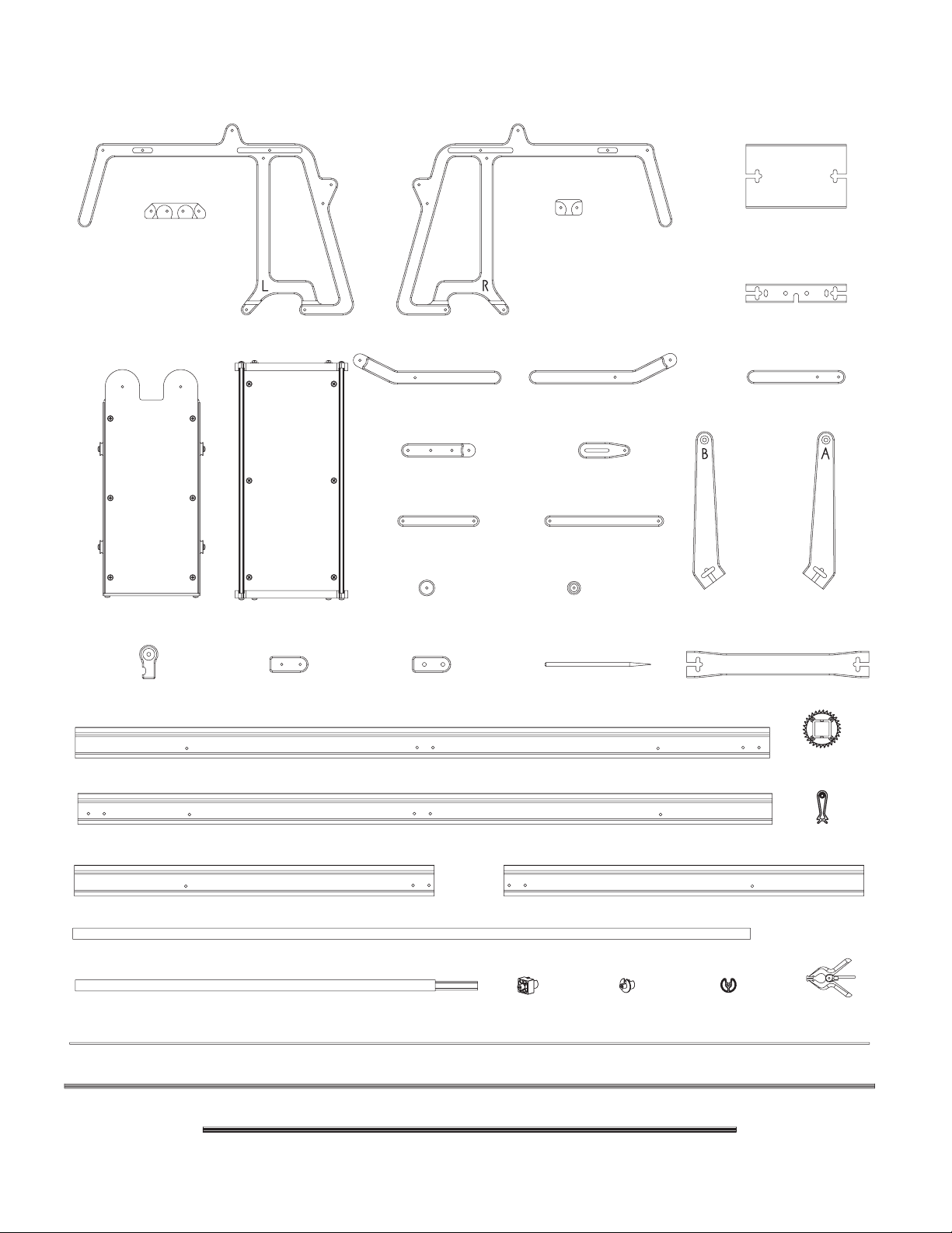
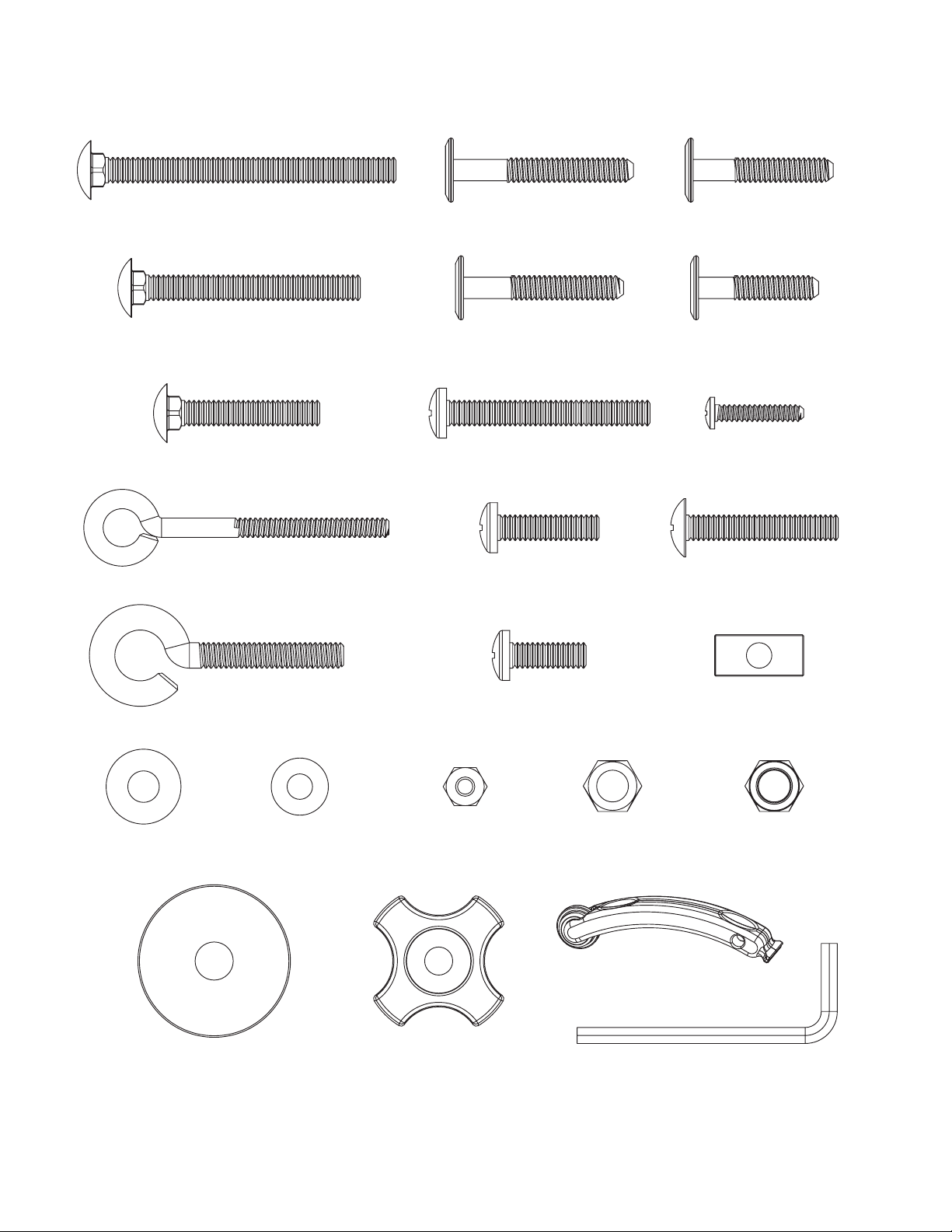
Parts List
Part List A............................................................................................................. 2
Part List B ............................................................................................................. 3
Part List C ............................................................................................................. 4
Care of Your Frame .............................................................................................. 5
Assembly Steps:
Step 1: Take Up Rail Mount End Assembly........................................................ 7
Step 2: Fabric Layer Rail Mount End Assembly................................................. 8
Step 3: Rail Mount End Assembly....................................................................... 9
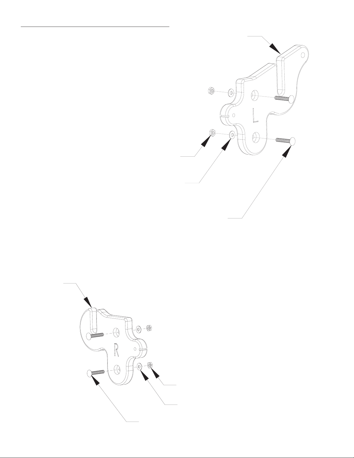
Step 4: Frame End Hardware Assembly............................................................ 10
Step 5: Frame End Assembly............................................................................. 11
Step 6: Side Leg Brace “B” Assembly .............................................................. 11
Step 7: Side Leg Brace “A” Assembly .............................................................. 12
Step 8: Legs to Frame End Assembly................................................................ 13
Step 9: Table Assembly ..................................................................................... 14
Step 10: Middle Leg Spacer Assembly.............................................................. 15
Step 11: Track Installation................................................................................. 16
Step 12: Frame End to Table Assembly ............................................................ 16
Step 13: Middle Leg Installation........................................................................ 17
Step 14: Middle Leg Assembly.......................................................................... 18
Step 15: Rail Assembly...................................................................................... 19
Step 16: Ratchet Stop Assembly........................................................................ 19
Step 17: Carriage Handle Assembly.................................................................. 20
Step 18: Cross Brace Assembly......................................................................... 20
Step 19: Cone Thread Holder Assembly ........................................................... 20
Step 20: Cone Thread Guide Assembly............................................................. 21
Step 21: Lever to Carriage Assembly ................................................................ 21
Step 22: Lever Linkage to Handle Assembly .................................................... 22
Step 23: Pedal Clamp to Handle Assembly ....................................................... 24
Step 24: Carriage to Frame Assembly ............................................................... 24
Step 25: Sewing Machine to Frame Assembly.................................................. 25
Step 26: Stylus Clamp Base Assembly.............................................................. 25
Step 27: Stylus Clamp Assembly....................................................................... 25
Step 28: Stylus Assembly .................................................................................. 25
Step 29: Stylus to Carriage Assembly ............................................................... 26
Step 30: Carriage Stop Assembly ...................................................................... 26
Optional 4th Pole.................................................................................................. 27
Fabric Installation............................................................................................. 28
Making Cloth Leaders......................................................................................... 29
Installing Your Fabric Layers to the Rails.......................................................... 30
Step 1: Quilt Backing to Second Rail ................................................................ 30
Step 2: Quilt Top to 3rd Rail.............................................................................. 30
Step 3: Batting.................................................................................................... 30
Step 4: Attaching Layers to the Take-Up Rail................................................... 31
Step 5: Putting Your Machine/ Carriages Onto Frame...................................... 31
Rolling Your Fabric ............................................................................................ 32
The Four-Inch Principle...................................................................................... 32
Bungee Clamp Assembly.................................................................................... 32
Copyright June 2005
Jim M. Bagley, GraceWood, Inc
(Reproduction Prohibited)

Little Gracie II
Parts List A
(1) Left Rail Mount End (1) Right Rail Mount End
(1) Left Frame Side
(1) Right Frame Side
(1) Right Take
Up Rail
Mount End
(1) Left Take
Up Rail
Mount End
(1) Left Fabric
Layers Rail
Mount End
(1) Right Fabric
Layers Rail
Mount End
(1) Table #1
(1) Table #2
(1) Table #3 (2) Carriage
Stop Base
(2) Carriage
Stop Clamp
(1) Left
Front Leg (1) Right
Front Leg (1) Right
Back Leg
(1) Left
Back Leg
(2) Middle
Leg "A"
(2) Middle
Leg "A"
(3) Cone
Thread Disk
2

Little Gracie II
Parts List B
(1) Left Handle (1) Right Handle (1) Lamp Holding
Cross Brace
(1) Back Handle
Cross Brace
(1) Stylus Base (1) Stylus Clamp
(1) Stylus Mount
(1) Bottom
Carriage
(1) Top
Carriage
(2) Side Leg
Brace " A"
(2) Side Leg
Brace " B"
(2) Middle Leg Brace
(1) Wooden Stylus
(3) 64" Crib Rail
(3) 34" Queen Rail
(3) Ratchet
Wheel
(3) Square
End Cap
(6) End Cap
Shoulder
(3) Round
End Cap
(3) Ratchet
Stop
(1) Back Crib Table Aluminum Track Support
(1) Front Crib Table Aluminum Track Support
(1) Back Queen Table Aluminum Track Support (1) Front Queen Table Aluminum Track Support
(3) Fabrifast Tubing
(4) Bungie
Clamp
(2) Middle
Leg Spacer
(2) Track
Support Splice
(1) Right
Back Lever (1) Front Lever
(1) Back Lever
Linkage
(1) Front Lever
Linkage
(1) Middle
Lever
(1) Pedal
Clamp
(1) Pedal
Clamp Wheel (3) Pedal
Clamp Spacer
(2) 65-1/2" Plastic Track
(2) 99-1/2" Plastic Track
(1) Left
Back Lever
-Pre-Installed in your 64” rail
-Pre-Installed in your Crib Table Aluminum Track Supports
3

Little Gracie II
Parts List C
(20) 1/4" X 1-1/2"
Carriage Bolt
(15 ) 1/4" X 45mm
Connector Bolt
(8) 1/4" X 1" Phillips
Pan Head Screw
(26 ) 1/4" X 3/4" Phillips
Pan Head Screw
(8) 1/4" X 2" Phillips
Pan Head Screw
(3) 1/4" X 1-1/2"
Truss Bolt
(6) #8 X 7/8"
Screw
(67 ) 3/16" Flat
Washer
(27 ) 1/4" Flat
Washer
(22 ) 1-1/4" Fender
Washer
(23 ) 1/4" Plastic
Knob
(20 ) 1/4" Nylock
Nut
(57 ) 1/4" Jam
Nut
(12) 1/4" Rectangle
Nut
(4 ) 1/4" X 30mm
Connector Bolt
(4 ) 1/4" X 3"
Carriage Bolt
(2) #10 X 3"
Eye Bolt
(1) 1/4" X 2"
Eye Bolt
(4) #10 Hex
Nut
(1) 4mm Allen Wrench
(2) 1/4" X 2-1/4"
Carriage Bolt
(3 ) 1/4" X 35 m
Connector Bolt
(2 ) 1/4" X 40 m
Connector Bolt
(1) Fabri-fast Tool
4

CARE OF YOUR LITTLE GRACIE
Your Little Gracie frame is a machine quilting system that can be used nished or unnished. Most use
it unnished with no problem, and doing so does not adversely affect warranty coverage. However, for extra
protection, or to give it a nished look, you may seal, stain and/or nish the frame using a number of different
applications. This is best done BEFORE YOU ASSEMBLE your frame.
To seal the wood, we recommend an application of tung oil or Danish Oil nish that will help preserve
the wood and will help to prevent warping. We recommend the McCloskey’s Tung Seal, DeftTM or WatcoTM
brands. Some prefer to use a urethane coat to add a more glossy nish.
Test stain on an inconspicuous place. Many different nishes and/or stains may be suitable for sealing
and beautifying your frame. You may want to consult your local paint retailer for nishes that are easy to apply
and dry hard–not oily.
Use and Storage Tip
--Store frame in a dry place. If not assembled, store with braces in vertical position. (This will prevent oor
moisture from seeping into the parts).
Five-Year Limited Warranty
GraceWood, Inc. will replace or repair, at our choosing, any part of the Little Gracie Machine Quilting
System which may be shown to be defective. This warranty does not cover parts damaged through misuse,
improper storage, improper assembly, loss, natural events and willful or accidental destruction. Defective parts
may be returned only with a valid RMA# which may be obtained by calling GraceWood, Inc. at
1-800-264-0644 or 1-801-485-6688.
NOTE: Warranty card must be lled out, stamped and mailed to the address on the card within 30 days of
purchase.
Contact Information
For Technical Support or any other correspondence concerning your Little Gracie, call 1-800-264-0644 ~
OR ~ E-mail: [email protected] ~ OR ~ Fax: (801) 908-8888 ~
OR ~ Write to:
The Grace Company
P.O. Box 27823
Salt Lake City, UT 84127
For details on accessories and other information, see us online at www.graceframe.com
For shipping of materials to The Grace Company address package (postage prepaid) to: The Grace Company,
2225 South 3200 West, SLC, UT 84119. Materials may be returned only with a valid RMA# or Returned
Merchandise Authorization Number which may be obtained by calling GraceWood, Inc. at
1-800-264-0644.
If you call after business hours (M-F 8:00 a.m. – 5 p.m., MST) be assured that your call will be returned
the next business day if you leave a message. Please report any errors in these instructions or make comments
to the following: [email protected]
Grace Quilting Frames and Hoops: Innovation and Evolution
Grace Quilting Systems have been developed over the past two decades with several original design
innovations. Additionally, because of feedback from many of the thousands of quilters who have purchased
and use our machine quilting systems, we have been able to make a frame that will truly enhance the entire
process of machine quilting from beginning to end. If you have any suggestions that will help us to improve
our product or service, let us know, using one of the above contact methods.
5

WELCOME!
As you begin assembly of your new Little Gracie home machine quilting system, keep in the mind the
following:
1) Plan to spend a minimum of 2-4 hours in assembly. This process will be simple and step-by-step.
2) Read through each step completely before beginning that step.
3) Using the parts list as a reference, take the parts out of the box and make sure that you have them all. (If there
is something missing or broken, contact the Grace Company at 1-800-264-0644. Our ofces are open from 8:00 am-
5:00 pm MST Mon.-Fri. If calling after hours, you may leave your message and we will promptly ship any item
needed).
4) For your convenience, an “L” and “R” have been etched into the INSIDES of most pieces to help you distinguish
between left and right parts and inside and outside of parts.
5) Identify Hardware Packets: All hardware is separated by type and each packet is labeled for ease in identication
you will nd packets located in a rectangular box.
6) This is a new product! We welcome your feedback on this product or these instructions. If you encounter a
problem during assembly or use of the Little Gracie, and you can’t seem to overcome it, call us before frustration
sets in!
Tools Needed:
7/16” Socket Wrench
Adjustable wrench
Phillips Screw Driver
Allen wrench (provided)
Fabri-Fast Tool (to be used when installing your fabric).
6

Step 1: Take Up Rail Mount End Assembly
Parts Needed: 1- Right and Left Take Up Rail Mount End
4- 1/4” Jam Nut
4- 3/16” Flat Washer
4- 1/4” X 1-1/2” Carriage Bolt
• Place one of the carriage bolts
through each of the holes on the Left
Take Up Rail Mount End, making sure
the head of the bolt is on the side with
the L.
Left Take Up Rail Mount End
Inside View
Right Take Up Rail Mount End
Inside View
HINT: Some holes in the wood pieces may be a
little tight for the hardware. If this is case, tap
in the hardware using the handle of your screw
driver.
• Place one washer and one jam nut on the end of the bolt.
• TIGHTEN JAM NUTS COMPLETELY ONTO EACH BOLT
• IMPORTANT: Completely tighten the jamb nut onto the bolt until the head of the bolt is pulled into the
counter-sunk hole.
• Repeat the above steps for the Right side.
Left Take Up
Rail Mount End
1/4" X 1-1/2"
Carriage Bolt
3/16" Flat Washer
1/4" Jam Nut
3/16" Flat Washer
1/4" Jam Nut
1/4" X 1-1/2" Carriage Bolt
Right Take Up
Rail Mount End
7

Step 2: Fabric Layers Rail Mount End Assembly
Parts Needed: 1- Right and Left Fabric Layer Rail Mount End
4- 1/4” Jam Nut
4- 3/16” Flat Washer
4- 1/4” X 1-1/2” Carriage Bolt
Right Fabric Layers Rail Mount End
Inside View
Left Fabric Layers Rail Mount End
Inside View
• Place one of the carriage bolts through each of the holes on the Left Fabric Layer Rail Mount End, making sure
the head of the bolt is on the side with the L.
• Place one washer and one jam nut on the end of the bolt.
• IMPORTANT: Completely tighten the jamb nut onto the bolt until the head of the bolt is pulled into the
counter-sunk hole.
• Repeat the above steps for the Right side.
Left Fabric Layers
Rail Mount End
1/4" X 1-1/2"
Carriage Bolt
3/16" Flat Washer
1/4" Jam Nut
1/4" X 1-1/2"
Carriage Bolt
3/16" Flat Washer
1/4" Jam Nut
Right Fabric Layers
Rail Mount End
8

Step 3: Rail Mount End Assembly
Parts Needed: 1- Right and Left Take Up Rail Mount End
1- Right and Left Fabric Layer Rail Mount End
1- Right and Left Rail Mount Ends
4- 1- 1/4” Fender Washer
4- 1/4” Plastic Knob
4- 1/4” Nylock Nut
4- 1/4” Flat Washer
• As shown in the drawing, place the bolts in the Right Take Up Rail Mount End through the rst slot on the Right
Rail Mount End.
• Place a fender washer followed by a plastic knob on the top bolt.
• Put a washer and then a nylock nut on the bottom bolt. NOTE!! Leave all the nylock nuts loose to allow the
washer to turn in your ngers!
• Follow the above steps for the Left Take Up Rail Mount End, Right Fabric Layer Rail Mount End, and the Left
Fabric Layer Rail Mount End.
Left Rail Mount End
Outside View
Right Rail Mount End
Outside View
• The nylon side of the nylock nut
faces out when threading it on the
bolt.
Left Rail Mount End
1-1/4" Fender Washer
1/4" Plastic Knob
1/4" Flat Washer
1/4" Nylock Nut
Right Rail Mount End 1-1/4" Fender Washer
1/4" Flat Washer
1/4" Nylock Nut
1/4" Plastic Knob
Right Rail Mount End 1-1/4" Fender Washer
1/4" Flat Washer
1/4" Nylock Nut
1/4" Plastic Knob
Right Rail Mount End 1-1/4" Fender Washer
1/4" Flat Washer
1/4" Nylock Nut
1/4" Plastic Knob
9

Step 4: Frame End Hardware Assembly
Parts Needed: 1- Right and Left Frame End
12- 1/4” X 1-1/2” Carriage Bolt
12- 3/16” Flat Washer
12- 1/4” Jam Nuts
Right Frame End
Outside View
Left Frame End
Outside View
• Place one of the carriage bolts through each of the holes, except for the two on each end, on the Right Frame
End, making sure the head of the bolt is on the side with the R.
• Place one washer and one jam nut on the end of the bolt.
• REMINDER: Completely tighten the jamb nut onto the bolt until the head of the bolt is pulled into the counter-
sunk hole.
• Repeat the above steps for the right side.
1/4" X 1-1/2"
Carriage Bolt 3/16" Flat Washer
1/4" Jam Nut
Right Frame End
1/4" X 1-1/2"
Carriage Bolt
3/16" Flat Washer
1/4" Jam Nut
Left Frame End
10

Step 5: Frame End Assembly
Parts Needed: 1- Right and Left Frame End
1- Right and Left Rail Mount End
4- 1-1/4” Fender Washer
4- 1/4” Plastic Knob
Right Frame End
Outside View
• Place the top two bolts on the Right Frame
End in the slots on the bottom of the Right
Rail Mount.
• Put a washer and then a plastic knob on
each of the bolts.
Left Frame End
Outside View
Step 6: Side Leg Brace “B” Assembly
Parts Needed: 2- Side Leg Brace “B”
1- Right Back Side Leg
1- Left Front Side Leg
2- 1/4” X 45mm Connector Bolt
2- 1/4” Rectangle Nut (threaded)
• Place a rectangle nut
vertically in the “t” slot of
the Side Leg Brace “B”, as
illustrated to the right.
• Follow the above steps again to complete the left side.
• The nylon side of the nylock nut faces out when
threading it on the bolt.
• NOTE!! Leave all the nylock nuts loose enough to
slide in the joint, and loose enough to allow the washer
to turn in your ngers!
• Connnect the Right Back Side Leg to the Side Leg
Brace “B” by threading the connector bolt through the
hole in the Right Back Side Leg and into the rectagle
nut. (Holding the rectagle nut in place, while using the
provided allen wrench to tighten the connector bolts.)
Back Right Side Leg
Inside View
1-1/4" Fender Washer
1/4" Plastic Knob
Right Frame End
Left Frame End
1-1/4" Fender Washer
1/4" Plastic Knob
Side Leg
Back Right
Side Leg
Brace "B"
1/4" Rectangle Nut
1/4" X 45mm
Connector Bolt
11

• Place a rectangle nut vertically in the “t” slot of the Side Leg
Brace “A”, as illustrated to the left.
• Connnect the Right Front Side Leg to the Side Leg Brace
“A” by threading the connector bolt through the hole in the
Right Front Side Leg and into the rectagle nut. (Holding the
rectagle nut in place, while using the provided allen wrench to
tighten the connector bolts.)
• Complete the above steps again to complete the Left Back
Side Leg.
Step 7: Side Leg Brace “A” Assembly
Parts Needed: 2- Side Leg Brace “A”
1- Right Front Side Leg
1- Left Back Side Leg
2- 1/4” X 45mm Connector Bolt
2- 1/4” Rectangle Nut (threaded)
Front Left Side Leg
Outside View • Complete the above steps again to complete the
Left Front Side Leg.
Front Right Side Leg
Inside View
Back Left Side Leg
Outside View
Side Leg
Front Right
Side Leg
Brace "A"
1/4" Rectangle Nut
1/4" X 45mm
Connector Bolt
Side Leg
Brace "B"
Side Leg Front Left
1/4" X 45mm
Connector Bolt
1/4" Rectangle Nut
Side Leg
Back Left
Side Leg
Brace "A"
1/4" X 45mm
Connector Bolt
1/4" Rectangle Nut
12

Left Frame End
Outside View
• Place a fender washer on the top bolt, and then thread and tighten
the plastic knob onto the bolt.
• Place the at washer on the bottom bolt, and then tighten the
nylock nut.
• Make sure nylock nuts are loose enough to allow the washer to turn
in your ngers.
• Follow the above steps to complete the left side.
• The nylon side of the nylock nut faces out when threading it on
the bolt.
• NOTE!! Leave all the nylock nuts loose enough to slide in the
joint, and loose enough to allow the washer to turn in your ngers!
Right Frame End
Outside View
• Put the Right Front Side Leg on the pre-
installed bolts on the Right Frame End (below
the Fabric Layer Rail Mount End).
• Place a fender washer on the top bolt, and
then thread and tighten the plastic knob onto
the bolt.
• Place the at washer on the bottom bolt,
and then tighten the nylock nut.
• Make sure nylock nuts are loose enough to
allow the washer to turn in your ngers.
• Put the Right Back Side Leg on the pre-
installed bolts on the Right Frame End (below
the Take Up Rail Mount End).
Step 8: Legs to Frame End Assembly
Parts Needed: 1- Right and Left Frame End
1- Right and Left Front Side Leg
1- Right and Left Back Side Leg
4- 1/4” Nylock Nut
4- 1/4” Flat Washer
4- 1- 1/4” Fender Washer
4- 1/4” Plastic Knob
1-1/4" Fender Washer
1/4" Flat Washer
1/4" Nylock Nut
1/4" Plastic Knob
1-1/4" Fender Washer
1/4" Plastic Knob
1/4" Flat Washer
1/4" Nylock Nut
13

• Place the Tabe #1 on the front crib table aluminum track support (as pictured above). ** You might want to stand
the table on it’s side to make it easier to tighten the nuts.**
• Put a phillips pan head screw through the middle hole on the Table #1 through the front crib table aluminum
track support, and then on the end of the phillips pan head screw put a at washer followed by a jam nut.
• Put a phillips pan head screw through the other two holes on the Table #1, and then put a at washer followed
by a jam nut on each end.
• Follow the above steps to attach the front crib table aluminum track support to the Table #2.
• Follow the above steps to attach the back crib table aluminum track support to the Table #1 and #2.
• Place the Table #3 on the front queen table aluminum track support (as pictured left).
Step 9: Table Assembly
Parts Needed: 1- Table #1
1- Table #2
1*- Table #3
1- Front Crib and *Queen Table Aluminum Track Support
1- Back Crib and *Queen Table Aluminum Track Support
12 or 18*- 1/4” X 3/4” Phillips Pan Head Screw
12 or 18*- 3/16” Flat Washer
12 or 18*- 1/4” Jam Nut
* Queen assembly ONLY
• Put a phillips pan head screw through the middle hole on
the Table #3 through the front queen table aluminum track
support, and then on the end of the phillips pan head screw
put a at washer followed by a jamb nut.
• Put a phillips pan head screw through the other two holes on
the Table #3, and then put a at washer followed by a jam nut
on each end.
•IMPORTANT! Carefully identify your Front and Back
Crib Track Supports based on the position of the holes.
NOTE: The Crib Back Track Support mounts to the “slot-
ted” side of the table.
1/4" X 3/4" Phillips
Pan Head Screw
3/16" Flat Washer
1/4" Jam Nut
1/4" X 3/4" Phillips
Pan Head Screw
3/16" Flat Washer
1/4" Jam Nut
Front Crib Table
Aluminum Track Support
Crib Table #2
Crib Table #1
Back Crib Table
Aluminum Track Support
1/4" X 3/4" Phillips
Pan Head Screw
3/16" Flat Washer
1/4" Jam Nut
Aluminum Track Support
14

• The 1/4 X 3/4” phillips pan head screws will go through the
end two holes with a washer and jam nut on the end.
• Follow the above steps for the other side
Step 10: Middle Leg Spacer Assembly
Parts Needed: 1- Crib Table (assembled)
1*- Queen Table (assembled)
2- Middle Leg Spacer
2*- Table Splice
4 or 8*- 1/4” X 2” Phillips Pan Head Screw
4*- 1/4” X 3/4” Phillips Pan Head Screw
4 or 12*- 3/16” Flat Washer
4 or 12*- 1/4” Jam Nut
• Place the at side of the Middle Leg Spacer
against the front crib table aluminum track support
(as show above, and to the left).
• Put a phillips pan head screw through the left hole following the same steps as you did for the right.
• Follow the above steps to attach the Middle Leg Spacer to the back crib table aluminum track support.
• Place your Crib Table #2 next to you Queen Table #3.
• Where your Crib Table meets your Queen table you will
place a Table Splice (at end against the aluminum track
support).
• You will place a 1/4” X 2” phillips pan head screw through
the center two holes in the aluminum track support and then
through the Table Splice. A washer and jam nut will go on the
end of the screws.
• You will place a 1/4” X 2” phillips pan
head screw through the center two holes
in the aluminum track support and then
through the Table Splice. A washer and jam
nut will go on the end of the screws.
• Put one phillips pan head screw through the
right most hole in the front crib table aluminum
track support, which will then go through the
Middle Leg Spacer.
• You will then put a at washer on the end of
the screw, which will be followed by a jam nut.
1/4" X 2" Phillips
Pan Head Screw
3/16" Flat Washer
1/4" Jam Nut
Table Splice
1/4" X 3/4" Phillips
Pan Head Screw
1/4" X 2" Phillips
Pan Head Screw
Middle Leg Spacer
3/16" Flat Washer
1/4" Jam Nut
15

Step 11: Track Installation
Crib Parts Needed: 2- 65-1/2” Plastic Track
1- Crib Table (assembled)
Queen Parts Needed: 2- 99-1/2” Plastic Track
1- Queen Table (assembled)
• Slide one of the plastic track (FLAT SIDE DOWN) into the front table aluminum track support.
• Slide the last plastic track (FLAT SIDE DOWN) into the back table aluminum track support.
Step 12: Frame End to Table Assembly
Parts Needed: 1- Right and Left Frame End
1- Table (crib or queen)
8- 1/4” X 1” Phillips Pan Head Screw
4-1/4” X 3/4” Phillips Pan Head Screw
• Place your Left Frame End on the left side of your table (Table #1). It
is recommended that you prop the right side of the table on something so
you can put the left side on rst.
• The two holes on the back of your Left Frame End is where the 1/4 X
1” phillips pan head screw go through to screw into the aluminum track
support.
99-1/2" Queen
Plastic Track
1/4" X 3/4" Phillips
Pan Head Screw
1/4" X 1" Phillips
Pan Head Screw
65-1/2" Crib Plastic Track
16

Instructions continued from previous page
• The 1/4 X 3/4” phillips pan head screw goes through the
aluminum track support to the Side Leg Brace. (as illustrated left).
• Two of the 1/4 X 1” phillips pan head screw go through the
front Left Frame End to screw into the aluminum track support,
similar to what you just did on the back.
• Follow the above instructions to attach your Right Frame End
to your table, except the Left Frame End can hold up your table.
Step 13: Middle Leg Installation
Parts Needed: 1 or 2*- Middle Leg (assembled)
2 or 4*- 1/4” Plastic Knob
2 or 4*- 1-1/4” Fender Washer
2 or 4*- 1/4” Nylock Nut
2 or 4*- 1/4” Flat Washer
*Queen Assembly ONLY
• Lay the Little Graice on it’s side with
the front down, as illustrated.
• Put the “B” side of your Middle Leg
on the bolts, which are on the front of
your frame.
• You will have to push
the “A” Side down
enough to get it on the
bolts on the back side of
your frame.
• It is okay to tap the
leg into place with your
hand, it will be a tight t
when you start
• The bolt to the right of
the “B” is where you will
put a at washer followed
by a nylock nut.
1/4" X 3/4" Phillips
Pan Head Screw
1/4" X 1" Phillips
Pan Head Screw
NOTE: This illustration shows the Middle Leg
Brace assembled to the Middle Legs. Do this
AFTER you have installed you Middle Legs to
the frame (Step 14).
1/4" Plastic Knob 1/4" Nylock Nut
1/4" Flat Washer
1-1/4" Fender
Washer
17

• On the other bolt you will put a fender washer and then a plastic knob.
• The right side is just opposite of the above instructions. The illustration on the previous page will help.
• Lay the Little Graice on it’s side with the front
down, as illustrated.
• Put the “B” side of your Middle Leg on the bolts,
which are on the front of your frame.
• The bolt to the right of the “B” is where you will
put a at washer followed by a nylock nut.
• On the other bolt you will put a fender washer
and then a plastic knob.
• You will have to push the “A” Side down enough to get it on the bolts on the back side of your frame.
• The right side is just opposite of the above instructions. The illustration on the previous page will help.
Step 14: Middle Leg Assembly
Parts Needed: 1 or 2*- “A” Middle Leg
1 or 2*- “B” Middle Leg
1 or 2*- Middle Leg Brace
2 or 4*- 1/4 X 45mm Connector Bolt
2 or 4*- 1/4 Rectangle Nut (threaded)
* Queen set up ONLY
• Connect the “A” and “B” Middle legs by placing the
connector bolts through each leg hole as pictured, and into
the Middle Leg Brace.
• Place a rectangle nut in the Middle Leg Brace so the
connector bolt can be screwed into the nut tight.
• NOTE if you are setting up for queen, you will assembly
two sets of legs.
1-1/4" Fender Washer
1/4" Plastic Knob
1/4" Flat Washer
1/4" Nylock Nut
1/4" X 45mm
Connector Bolt
1/4" Rectangle Nut
Middle Leg "A"
Middle Leg "B"
18

• Place a plastic end
cap in the hole on the
outside of the Right
Frame End and use a screw to tighten the plastic end cap to the outside of
the Right Frame End.
•Follow the above steps for the other two rails on top.
• The teeth on the remaining two rails will roll clockwise.
• On the left side of the rail you will rmly place the square plastic cap, and on
the right side you will put the round plastic cap in the rail rmly. Be sure that
they are completely seated into the rail with no gaps.
• Place the ratchet wheel on the square plastic cap, and then place all your rails on
the oor where they can lay at.
• Take one of your rails and place it in the bottom front rail position, with the cog
wheel on the left side and the round plastic cap on the right side, as shown below.
**Make sure the teeth on the cog
wheel are facing counter clockwise.**
Step 15: Rail Assembly
Parts Needed: 3- 64” Rail (Crib)
3- 34” Rail w/ Coupler (Queen ONLY)
3- Square Plastic Cap
3- Round Plastic Cap
6- Plastic End Cap
6- #8 X 7/8” Screw
3 - Ratchet Wheels
• Choose the rail size that corresponds to
the frame size you have set up, and follow the
above diagrams to assist you in assemblying
that particular size.
Step 16: Ratchet Stop Assembly
Parts Needed: 3- Ratchet Stops
3- 1/4” x 1-1/2 Truss Bolt
• You will need to put the bolt through the ratchet stop.
• As pictured right, you will screw the ratchet stops into the holes near the
ratchet wheels. (The bottom rail the ratched stop goes to the left, while the
other two the rachet stop goes to the right of the ratchet wheel.
• Place a plastic end cap in the hole on the outside of the Left
Frame End. You will then screw the plastic end cap to the square
plastic cap.
Round Plastic Cap
Square Plastic Cap
Ratchet Wheel
64" Crib Rail
34" Queen Rail
Queen Size
Round Plastic Cap
Square Plastic Cap
Ratchet Wheel
64" Crib Rail
Crib Size
Plastic End Cap
#8 X 7/8" Screw
1/4" X 1-1/2"
Truss Bolt
Ratchet Stop
19

Step 17: Carriage Handle Assembly
Parts Needed: 1- Top Carriage (preassembled)
1- Right and Left Handle Base
4- 1/4” X 30 mm Connector Bolt
4- 1/4” Jamb Nut
• Stand your Top Carriage up so you can see the top of
your Handles.
• Attach the Back Handle Cross Brace with connector
bolts and rectagle nuts as illustrated.
• Attach the Front Handle Cross Brace in the same manner
as you did the back one.
• Take the three Cone Thread Holders and place them on either the
back right or the left side.
• Put a connector bolt through
both holes on the bottom of your
Left Handle Base and through
your Top Carriage.
• You will then put the carriage bolt through the Cone Thread Holders and your Top Carriage, where you will put a
washer and then a plastic knob on to hold the Cone Thread Holders in place.
• Under your Top Carriage is where you will put
the jam nut on your connector bolt.
• It is easier if you will bend the handle out a little so
you can get the nut started on the bolt. Then you can
straighten the handels and tighen the nut onto the bolt.
• Follow the above steps to attach your Right Handle Brace
Step 18: Cross Brace Assembly
Parts Needed: 1- Top Carriage (with handles)
1- Front Handle Cross Brace
1- Back Handle Cross Brace
4- 1/4” X 45 mm Connector Bolt
4- 1/4” Rectange Nuts (threaded)
Step 19: Cone Thread Holder Assembly
Parts Needed: 1- Top Carriage (with handles & braces)
3- Cone Thread Holders
1- 1/4” X 3” Carriage Bolt
1- 1/4” Flat Washer
1- 1/4” Plastic Knob
Pedal Platform
Lamp Holding
Cross Brace
1/4" Rectangle Nut
1/4" X 45mm
Connector Bolt
1/4" Plastic Knob
1/4" Flat Washer
Cone Thread
Holder
1/4" X 3"
Carriage Bolt
1/4" X 30mm
Connector Bolt
Right Handle
Left Handle
1/4" Jam Nut
Top Carriage
20
Table of contents
Other GraceWood Sewing Machine manuals