Gradall XL4100 User manual

July 2002
Starting S/N
Undercarriage - G04391
OPERATOR'S MANUAL
GRADALL
406 Mill Avenue S.W.
New Philadelphia, OH, 44663, USA
Telephone: (330) 339-2211
Fax: (330) 339-3579
XL4100 CARRIER
24604133
Form #29612 Original Issue 8/96


Safe operation depends upon reliable equipment and proper operating
procedures. Performing the checks and services described in this manual
will help to keep your Gradall Excavator Carrier in reliable condition and
use of the recommended operating procedures can help you avoid
accidents. Because some procedures may be new to even the experienced
operator we recommend that this manual be read, understood and followed
by all who operate the unit.
Strict attention to, and compliance with, instructions provided in this manual,
the XL4100 & XL4200 Upperstructure Operation & Lubrication Manual, as
well as the EMI & Gradall Hydraulic Excavator Safety Manuals and all
instructional decals and plates affixed to the machine, will help avoid
personal injury and damage to the equipment. The information provided is
not intended to cover all situations; it would be impossible to anticipate and
evaluate all possible applications and methods of operation for this unit.
Any procedure not specifically recommended by The Gradall Company
must be thoroughly evaluated from the standpoint of safety before it is
placed in practice. If you aren’t sure, contact your Gradall Excavator
Distributor before operating.
®
The Gradall Company retains all proprie-
tary rights to the information contained in
this manual.
The Company also reserves the right to
change specifications without notice.
Gradall is a registered trademark for
hydraulic excavators, hydraulic material
handlers and attachments manufactured
by The Gradall Company.
The Gradall Company
406MillAvenue,S.W.,NewPhiladelphia,Ohio44663
Do not modify this machine without written
permission from The Gradall Company. Use only
genuine Gradall replacement parts.
IMPORTANT SAFETY NOTICE
OTHER NOTICES
FormNo.29612 7/96 B 1 K


INTRODUCTION
General
This manual provides important information to
familiarize you with required operator maintenance and
with safe operating procedures for the Gradall wheeled
excavator undercarriage.
Bec
ause two operators are sometimes assigned to the
unit, operator information for the upperstructure and for
the undercarriage is provided in separate manuals.
The undercarri
age includes a separate operator’s stat
ion
for control of undercarriage functions and is equipped
with a separate engine to propel the unit.
Throughout this manual, the term “carrier” will be used
to designate the excavator under carriage.
Related Manuals
Separate publica
tions are furnished with the Gradall t
o
provide information concerning safety, replacement
parts, detailed maintenance procedures, vendor
components and operation of the upperstructure.
You must read and understand the Gradall Upper-
structure Operation & Lubrication Manual, the Gradall
Hydraulic Excavators Safety Manual and the EMI
Hydraulic Excavator Safety Manual before operating
the upperstructure.
If you have any que
stions regarding the Gradall Carrier
or the Upperstructure, contact your Gradall Distributor;
he is thoroughly familiar with the unit and will be happy
to help you.
Operator Qualifications
The operator must hold a valid, applicable driver’s
l
icense which requires acceptable age, vision, hearing,
manual dexterity and response. He must also be in
acceptable physical and mental condition (not
undergoing medical treatment or using drugs or alcoho
l
which would violate traffic laws.)
Before driving the
unit on the highway or operating t
he
excavator at a worksite, the operator must familiarize
himself with the machine by practicing in a safe, open
area not hazardous to people or property.
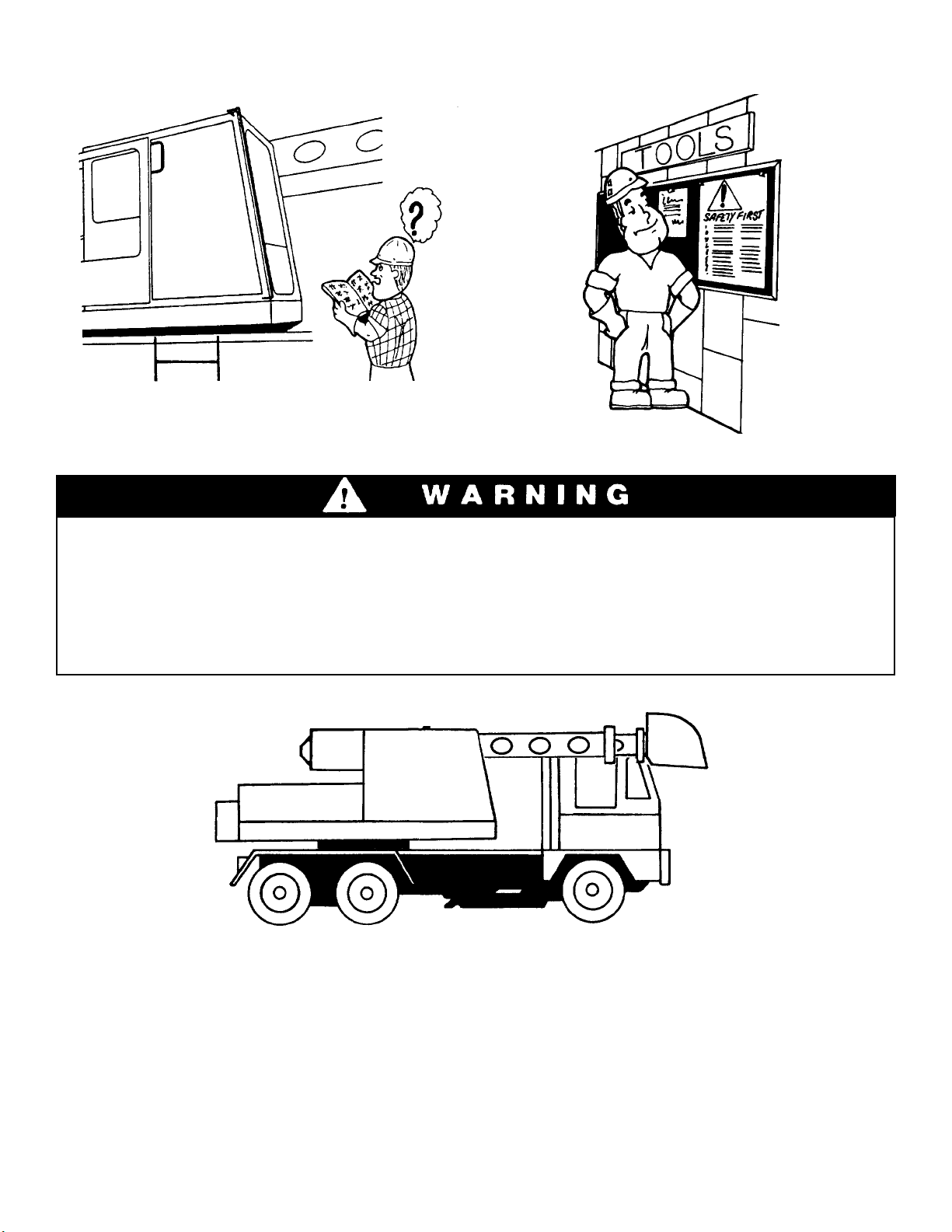
The operator must read, understand and comply with
instructions contained in the following material
furnished with the excavator.
This Operation & Lubrication Manual
EMI Hydraulic Excavator Safety Manual
All Instructional decals and plates
If driver will also operate upperstructure:
XL4100 & XL4200 Upperstructure Operation &
LubricationManual
Gradall Hydraulic Excavators Safety Manual
Models Covered
Wheeled carriers for the XL4100 Gradall Hydraulic
Excavators are furnished with the following basic
carrier variations to suit job applic
ation and contract
or
preference:
Driving axles at rear only (6x4) or driving axles at both
front and rear (6x6).
Where information in this manual applies only to
certain units, it will be so noted.
Orientation
When used to indicate direction or location, the terms
front, rear, left and right relate to the orientation of a
person sitting in the driver’s seat.
Serial Number Location
The carrier
nameplate is located on the right side of the
carrier frame. Be sure to specify the serial number (on
nameplate) when ordering parts and when discussing
procedures and applications with your distributor.
2

This symbol indicates an extreme hazard which
would result in high probability of death or
serious injury if proper precautions are not
taken.
This symbol indicates a hazard which could
result in death or serious injury if proper
precautions are not taken.
This symbol indicates a hazard which could
result in injury or damage to equipment or
property if proper precautions are not taken.
SAFETY HIGHLIGHTS
Read and understand this manual and “EMI Safety Manual” before starting,
operating or performing maintenance procedures on this carrier. Do not
permit this carrier to be driven by an operator who cannot read English
unless these manuals have been read and explained to him and his full
understanding is determined. Keep these manuals in cab.
If driver will operate upperstructure, he must also read and understand
Gradall Upperstructure Operation & Lubrication Manual and Gradall
Hydraulic Excavators Safety Manual.
Watch for these symbols; they are used
to call your attention to safety notices.
DANGER
WARNING
Maintain three point contact with grab handles
and steps when climbing on and off the machine.
Never jump from the machine.
Repair or replace damage steps and grab
handles.
Perform all “CHECKS & SERVICES BEFORE
STARTING ENGINE (pages 13 & 14), “CHECKS
AFTER STARTING THE ENGINE” (page 17)
and “CHECKS BEFORE DRIVING” (page 17)
before driving the carrier. Complete all required
maintenance before driving the carrier.
3

SAFETY HIGHLIGHTS
Learn to recognize ‘PINCH POINTS’
4
Boom Holes Stay clea of PINCH POINTS. Getng
caught in a pinch point can cause
serious indjry or death.
Boom Cradle
Acces Covers Boom
Bucket & Linkage
Counteweight & Another Object Upperstructure & Carrier

Stay clear of moving fan, belts, pulleys,
meshing gears, drive shafts and other moving
parts. Do not operate without covers and guards in
place.
SAFETY HIGHLIGHTS
Check to be sure all DANGER, WARNING,
CAUTION and INSTRUCTION DECALS are in
place and can be read. Clean or replace decals as
required.
Some owners alter their machines. Check to be
sure your machine fits the pictures and description
in this manual. If it differs, or if you aren’t sure,
contact your Gradall distributor before you run
yourunit.
Always sound horn to warn others of unexpected
machine movements (horn button is located at top
of left joystick).
The unit is also equipped with an automatic back-up
alarm to warn others of reverse travel.
An automatic travel alarm is also provided to warn
of remote control travel in either direction.
Keep steps and deck areas free of mud, oil, grease
and other foreign material. Replace non-skid
surface material as required.
Never carry a water can, equipment, or other
worker’s tools or personal items on the
machine. Such items can cause other workers to
approach the machine without your knowledge and
result in serious injury or death.
5

SAFETY HIGHLIGHTS
Be particularly careful if this is not the machine
you usually operate. Read the manuals listed on
page 2 and then operate the unit in a safe, open
area to become familiar with the controls. WARNING
Travel on off-highway grades is
recommended only under the following
conditions:
Boom secured in rest
Tires properly inflated
Surface is firm enough to support unit
TRAVEL TO AND FROM JOBSITE ONLY UNDER FOLLOWING CONDITIONS:
Boom secured in rest
Mirrors clean and properly adjusted
Seat belt buckled snugly across lap
Door secured in closed position
Plan your route
Bucket secured to boom
Learn and follow your employer’s safety rules.
Surface provides adequate traction to
prevent slipping
Surface is not rough enough or steep
enough to cause tipping
Transmission is in Lo Lo or Lo gear
range.
No load attached to any part of machine
Joystick switch in off position
Travel in accordance with local requirements
Tires inflated to proper pressure
Upperstructure engine stopped
6

Be sure windows andd oors are securely latched in
open or closed position when operating. Replace
defective latches and weak access cover support
struts immediately.
SAFETY HIGHLIGHTS
Use boom tie-down device to secure boom in
rack when traveling between jobsites.
Inspect brakes before driving carrier after
digging.
NOTE: This illustration shows a typical automatic
slack adju
ster. Refer to instructions provided on ins
ide
back cover of this manual
Apply digging brake and stop engines.
Check the following for apparent damage:
Brake actuator chambers and rods
Brake actuator brackets
Slack adjusters
With brake applied, actuator rod should form an
approximate right angle with slack adjuster.
Do not drive unit until any damage or mal-
function has been repaired.
Check to be sure windows and mirrors are clean
and that mirrors are properly adjusted for your driving
position and machine configuration. Ensure adequate
visibility for safe travel.
Whenever rotating equipment (such as a
mower or mixer) is installed on machine,
adequate shielding must be installed to
prevent flying debris.
Never operate such equipment with other
persons within range of possible flying
debris. Be certain that mower discharge
is never aimed at persons, equipment or
structures.
As an additional precaution, safety glass
and appropriate window guards must be
installed on machine.
•
•
•
7
DANGER
1.
2.
3.
4.

SAFETY HIGHLIGHTS
If required, secure attachment as shown to prevent
driftwhiletraveling.
Check for proper slack adjuster operation in
accordance with Lubricati
on & Maintenance Schedule
(page 33).
Know overall height of your unit before traveling.
Approach unknown clearances slowly.
Remember, getting too close to unstable ground
or the edge of an excavation can cause the
machine to tip.
Always apply digging brake to prevent carrier
movement while operating upperstructure.
Do not carry passengers or move the unit until all
other persons have gotten off and are clear of the
machine. Do not carry passengers in upperstructure
cab.
8

Decals Inside Cab
9
DEATH
UNLAWFUL
OR INJURY MAY RESULT FROM
CONTACTING ELECTRICAL LINES
TO PLACE ANY PART OF THIS
MACHINE OR LOAD WITHIN 10
FEET OF HIGH VOLTAGE LINES
OFUPTO50,000VOLTS.
TO PREVENT INJURY,
STAY CLEAR OF MOVING
PARTS. FASTEN COVERS
BEFORESTARTING
ENGINE.READSERVICE
MANUALBEFORE
ADJUSTINGOR
SERVICING.
CAUTION
ALLOWINCREASEDSTOPPING
DISTANCEWIH NEWBRAKES. BRAKE
CAPABILITYWILLIMPROVEAFTER
SEVERALSTOPS.
PART NO. 8688-1755
Located on right cab window
Part No. 8688-1755
Located on right cab window
Part No. 8688-1305
Located on right cab window
Part No. 8068-3092
Located inside cab door &
above engine compartment
Part No. 7702-3004
Located on dashboard
Part No. 8068-3091
Located inside cab door
Part No. 8360-1011
REMOTECONTROL ENGAGEMENT PROCEDURE
APPLYPARKINGBRAKE.
STARTCARRIERENGINE AND FULLYCHARGEAIR
SYSTEM(125P.S.I.).
SHIFTTRANSMISSION TO LO-LOORLO.
TURN ENGINE OFF. DO NOT OPERATE CARRIER
ENGINE.
KEEPINGFEET CLEAR OR CLUTCHPEDAL.
MOVEDIGGINGBRAKE LEVER TO ONPOSITION.
RELEASEPARKING BRAKE.
WARNING
ROTATION OF STEERING WHEEL OCCURS
DURING REMOTE OPERATION. 8068-3093
1.
2.
3.
4.
5.
6.
Located inside cab door
Part No. 8068-3093
8369-3010 AXLE
DIFFERENTIAL
LOCK UNLOCK
Located on dashboard
Part No. 8068-3093
Located on dashboard
Part No. 8369-3010
For 6BTA5.9 Engine only
Located on dashboard
Part No. 8068-3122
NOTICE:
THROTTLESTOP ADJUSTED TO LIMIT ENGINE
SPEED TO 2500 RPM HIGH IDLE NO-LOAD.
DO NOT READJUST TO HIGHER SPEED!!!
8068-3127
For 6BTA5.9 Engine Only
Located on right cab wall
Part No. 8068-3127
Located on cab wall
Part No. 7738-3675
Located on right cab window
Part No. 8395-3002

Decals Outside Cab
10
7702-3003
7702-3008
9104-3210
Located at right of cab door
Part No. 7702-3003
Located near coolant filler cover
Part No. 9104-3310
Located on back of cab
Part No. 8360-1018
Located near fuel filler cover
Part No. 7702-3008
USE TWO
HANDS WHEN
CLIMBING ON
MACHINE.
PRESSURIZED
COOLINGSYSTEM
REMOVE CAP
SLOWLY
KEEP CLEAR OF
MACHINE SWING AREA.
NYLON BRAKE
LINES MAY BE
DAMAGED BY
HEAT. AVOID
WELDING ON
OR AROUND
CARRIER FRAME
UNLESS LINES
ARE PROTECTED
FROM HEAT.
IMPORTANT
To prevent damage to the electrical system when
using booster battery or charger always connect
(+)POSITIVETOPOSITIVE
(-)NEGAIVETONEGATIVE
Located on right frame rail
Part No. 7702-3029
Located on air reservoir
Part No. 7702-3002
Located inside battery box cover
Part No. 7702-3007
For 6BTA5.9 Engine Only
Located on air cleaner
Part No. 8068-3123
DONOTADD ETHER
ORUSE AEROSOLCANS
DIESEL FUEL
NONO
NONO
NOTICETICE
TICETICE
TICE!!
!!
!
THIS UNIT IS EQUIPPED

INSTRUMENTS AND INDICATORS
WARNING
Alternator Indicator Light
Voltmeter
Speedometer/Odometer
Hi/Lo Beam Indicator Light
Tachometer (optional)
Air Pressure Gage (front)
Low Air Indicator Light
Fuel Gage
Differential Lock Indicator Light
Digging Brake Indicator Light
Oil Pressure Gage
Coolant Temperature Gage
Hourmeter
Turn Signal/Hazzard Indicator Light
Air Pressure Gage (rear)
1.
2.
3.
4.
5.
6.
7.
8.
9.
10.
11.
12.
13.
14.
15.
Do not move carrier while low air light is
glowingorwhi
leanyauxiliarydeviceissign
al-
ing a dangerous condition.
11

CONTROLS
Front Wheel Drive Toggle (6x6 only)
Interaxle Differential Toggle
Dome Light Switch
High/Low Beam Switch
Clutch Pedal
Brake Valve Pedal
Accelerator Pedal
Range Preselection Lever
Gear Shift Lever
Deep Reduction Button
Countershaft Brake Button
Heat Control Knob
Heater Fan Switch
Defroster Fan Switch
Differential Lock Toggle
Digging Brake Toggle
Parking Brake Knob
LightSwitch
IgnitionSwitch
Turn Signal Lever
Hazard Flasher Switch
Horn Button
Windshield Wiper/Washer Switch
1.
2.
3.
4.
5.
6.
7.
8.
9.
10.
11.
12.
13.
14.
15.
16.
17.
18.
19
20.
21.
22.
23.
12

CHECKS AND SERVICES
BEFORE STARTING ENGINE
Complete all required maintenance before driving the carrier
Inspect carrier for obvious damage, vandalism
and needed maintenance. Check for signs of fuel,
lubricant, coolant and hydraulic leaks. Open access
doors and look for loose fittings, clamps, com-
ponents and attaching hardware. Check brake and
steering systems for obvious damage. Check
operation of all lights and repair as necessary
before operating. Broken windows must be replaced
before operating. If spark arrestors are used, be sure
they are in place and in good working order.
Check for fully charged fire extinguisher on rear
wall in carrier cab. Be sure to read and understand
instructions on extinguisher. Replace extinguisher
as necessary.
Check fluid level in windshield washer reservoir
on rear wall in carrier cab. Add windshield washer
solvent as necessary.
WARNING
Use extreme caution when checking
items beyond your normal reach. Use
an approved safety ladder.
Check for secure stowage of boom and any
auxiliary equipment or material.
Check position of DIGGING BRAKE toggle.
Toggle should be in OFF position for operation
from carrier cab. Be sure parking brake is applied
before moving toggle to OFF position.
13

Always check engine coolant level by
observing level in coolant expansion
container. Do not attempt to remove
radiator cap from a hot radiator. Hot
coolant, under pressure, can be expelled
and cause serious burns.
Lubricate unit as indicated on lubrication chart.
Check fuel level and reple
nish as necessary. Refu
el
at the end of the work shift to minimize
condensation.
W A R N I N G
Engine should be turned off while
refueling. Be sure area is free of open
flame, sparks or any condition which
could cause fuel to ignite.
Check oil level in engine crankcase and replenish
as necessary. DO NOT OVERFILL.
Check engine coolant level and replenish as
necessary. Be sure anti-freeze solution is adequate
for expected temperatures. Be sure radiator fins are
clean.
W A R N I N G
14

Cold weather starting aids
Diesel engine ignition is accomplished by heat
generated when fuel/air mixture is compressed
within the cylinders. Because this heat may be
insufficient to start a cold engine in cold weather,
the use of starting aids has become common
practice.
Because of the wide variety of starting aids available
WARNING
DO NOT us
e ether starting aid if air system
is
equipped with an alcohol moisture evap-
orator.
it would be impractical to attempt to provide
specific instructions for their use in this manual.
Carefully follow instructions furnished with your
starting aid.
If you use a starting aid employing ether or a
similar substance pay particular attention to
manufacturer’s warnings.
Position throttle at low idle.
Turn ignition switch fully clockwise to engage
starting motor. Release key immediately when
engine starts. If engine fails to start within 20
seconds, release key and allow starting motor to
cool for a few minutes before trying again.
After engine starts, observe oil pressure gage. If
gage remains on zero for more than 15 seconds,
stop engine and determine cause. Correct cause of
malfunction before attempting to restart engine.
Warm up engine at approximately 1000 RPM until
coolant temperature reaches operating range,
(approximately 140° F. [60° C.] ).
Starting Diesel Engine (Cummins)
NOTES: Your unit may be equipped with standard
6BTA5.9, 200 HP engine or optional 6CTA8.3,
245 HP engine.Refer to engine Model/SN/Data
plate to determine which engine you have.
Standard 6BTA5.9 engines are equipped with an
ether injection system which is engaged automati-
cally below 32° F. (10° C.).
Optional 6CTA8.3 engines are not eqipped with
an ether starting aid unless it is ordered as an option.
Be sure transmission is in neutral (neutral start
switch) and parking brake is applied.
Turn ignition switch to ON position.
NOTE: If engine is being started at beginning of work shift be sure to
perform all “CHECKS AND SERVICES BEFORE STARTING ENGINE”
ENGINE OPERATION
C A U T I O N
Do not engage starting motor while fly-
wheel or starting motor Is rotating. Serious
damage could result.
3.
4.
5.
6.
1.
2.
15

Normal engine operation (Cummins)
Observe volt meter water temperature and oil
pressure gages trequently to be sure all engine
systems are functioning properly.
Be alert for unusual noises or vibration. When
an unusual condition is noticed stop in a safe area
and shut off engine. Determine cause and correct
beforecontinuing.
Early recognition and correction of unusual con-
ditions can often prevent a major breakdown.
Apply load to engine gradually; shock loads are
hard on all drive line components.
When using engine braking power (downshifting
or releasing acclerator and permitting carrier to
“push” engine) to slow travel take care to avoid
overspeeding the engine (exeeding governed
RPM - 22 00 RPM). The governor has no control over
engine speed when engine is being “pushed” by
carrier load.
Select an appropriate gear ratio and use service
brake to assist in slowing travel down steep grades.
Permitting the engine to labor under too great a
load for the gear ratio being used (lugging the
engine) will shorten engine life. Shift to the proper
gear ratio for conditions.
Avoid prolonged idling. Idling causes engine tem-
perature to drop and this permits formation of
heavy carbon deposits and dilution of lubricating oil
by incompletely burned fuel. If the engine is not
being used turn it off.
Do not “gun” engine before shut down; this
practice causes raw fuel to remove oil film from
cylinder walls and dilute lubricant in crankcase.
Stop engine by turning ignition switch to “OFF”
position.
W A R N I N G
Do not operate carrier engine when
operating upperstructure.
Stopping the engine (Cummins)
Operate engine at idle speed for a few minutes
before turning it off. This allows engine coolant and
lubricating oil to carry excessive heat away from
critical engine areas. This is especially important
for turbocharged engines.
16
Table of contents
Other Gradall Excavator manuals