EVERDIGM EPG05 Manual

-+
OPERATION &
MAINTENANCE MANUAL
Multi Purpose Grab
Document No.: MSAGUS.0005 Revision Date: 2014-09-23

- 2 -
FOREWORD
WARNING!
It is very important for you to read and understand this manual before operating and to keep
the instructions provided herewith. Never fail to follow the instruction related to safety.
This manual contains instructions and information on safe and correct use of EVERDIGM Grabs.
Please read and understand this manual before operation, inspections and maintenance of the grab
Keep this manual with your equipment all the time for your quick and easy reference, and read it regularly.
Do not operate the grab until you have been trained in the use of all operating controls and understand
the hydraulic grab operation
Get a replacement manual from EVERDIGM dealer if you lost it.
If you transfer the grab to the other, do transfer this manual as well.
The figures in this manual is for better understanding and may not correspond exactly to the grab. For
exact shape, refer to the parts list or ask EVERDIGM.
For the purpose of constant product improvement, some parts of this manual may be changed. If you
found the parts unclear or not corresponding to the grab, call and consult EVERDIGM dealer or service
center
Important information on safety is described in the safety information chapter of this book. Be familiarized
with the instructions on the safe operation and observe the instructions before and during operation
Injury, death or damage caused by unauthorized product modifications and operation under unallowed
application will not be responsible by EVERDIGM. Consult EVERDIGM for such modifications and
applications.
Use EVERDIGM genuine parts. EVERDIGM takes no responsibility for damages caused by use of non-
EVERDIGM spare parts.
For warranty, we refer you to the warranty conditions provided separately.
We always exert all our efforts for your satisfaction, and promise you quick and constant service.
We thank you for using EVERDIGM grab and wish you a good luck in every your job,
Sep. 2014
EVERDIGM.
Copyright © 2014 Everdigm Corp. All rights reserved.
This manual is copyrighted by Everdigm Corp. with all rights reserved in accordance with prevailing law.
It is positively prohibited to use or reproduce its contents in whole or in part without prior written permission.

- 3 -
TABLE OF CONTENTS
FOREWORD ........................................................................................................................................... 2
1. Safety Information ............................................................................................................................... 4
1.1. Basic safety information.............................................................................................................. 5
1.2. Preparation for safe operation .................................................................................................... 6
1.3. Safety information for operating the grab ................................................................................... 7
1.4. Safety information for maintenance of the grab.......................................................................... 8
2. Configuration and ordering information............................................................................................. 10
2.1. Main components...................................................................................................................... 10
2.2. Option components................................................................................................................... 10
2.3. Mounting dimension for the adapter plate .................................................................................11
3. Technical specifications..................................................................................................................... 12
4. Markings and labels .......................................................................................................................... 13
5. Installation ......................................................................................................................................... 15
5.1. Lifting the grab .......................................................................................................................... 15
5.2. Requirements on the carrier ..................................................................................................... 15
5.3. Installation of hydraulic piping on the carrier ............................................................................ 17
5.4. Mounting the hydraulic grab...................................................................................................... 18
5.5. Adjustment of the rotation device.............................................................................................. 20
6. Operating the grab ............................................................................................................................ 22
6.1. Preparation for safe and correct operation ............................................................................... 22
6.2. Greasing.................................................................................................................................... 22
6.3. Operation .................................................................................................................................. 23
7. Inspection and Maintenance ............................................................................................................. 29
7.1. General information .................................................................................................................. 29
7.2. Maintenance intervals............................................................................................................... 30
7.3. Tightening torques .................................................................................................................... 31
7.4. Hydraulic oil............................................................................................................................... 32
8. Dismounting and Storing the grab..................................................................................................... 34
9. Trouble shooting................................................................................................................................ 35
- 4 -
1. Safety Information
This manual describes correct use of the product and safety messages. Important or certain instructions in
this manual are marked with symbol. When you see this symbol provided in the manual or on the
product, be alert to the possibility of personal injury or death. Be sure to observe the instruction in the safety
message.
The safety messages in this manual do not describe all the possibilities of personal injury or death or of
damages to the product. This safety manual and the marks with symbols are intended to provide some of
basic instructions for safe operation, inspection and maintenance. It is operator‟s responsibility to observe
the safety instructions and regulations though this manual does not include all the possible situations.
Remember! Safety is up to you
Safety Alert Symbol
The SafetyAlert Symbol represents that ATTENTION is involved.
If you see the mark in this manual or on the products, never fail to read and
observe the instructions for safe operation.
Signal Words
The words “DANGER”, “WARNING”, “CAUTION”and “IMPORTANT”appeared with the above Safety Alert
Symbol indicate degree of risk of hazards or unsafe practices. All four degrees of risk indicate that safety is
involved. Observe precautions indicated whenever you see the Safety Alert Symbol, no matter which signal
word appears next to the “Exclamation Point”symbol.
DANGER!
Indicates imminent hazard of a situation that, if not avoided, is very likely to cause
death or extremely serious injury. It may also be used to alert against product that
may exploded or detonate if handled or treated carelessly.
WARNING!
Indicates potential of a hazardous situation that, if not avoided, could result in serious
injury or death. It may also be used to alert against a highly unsafe practice.
CAUTION!
Indicates potential of a hazardous situation that, if not avoided, could result in minor
or moderate injury. It may also be used to alert against a general unsafe practice.
IMPORTANT!
Indicates potential of damages that, if not avoided, could caused to the product or
shorten the product life.
- 5 -
1.1. Basic safety information
WARNING!
The following instructions are those that should never be fail to observe in operation of
construction equipment.
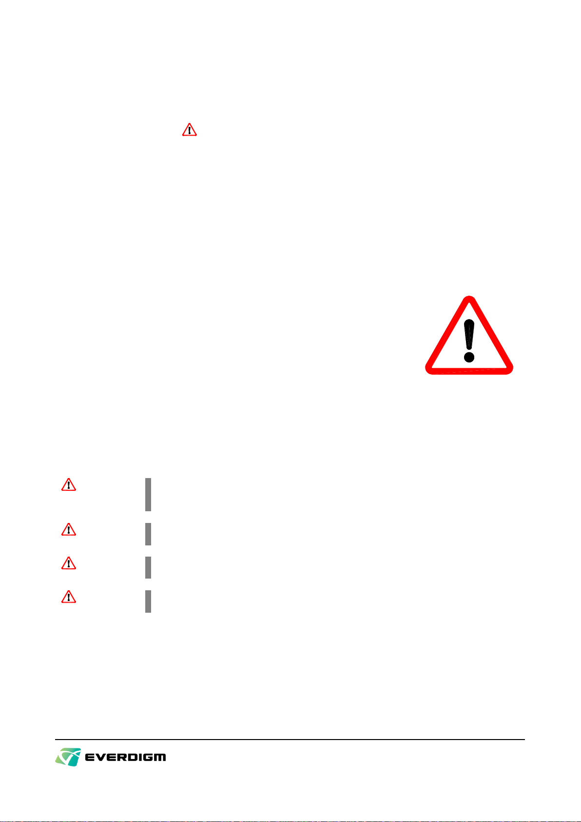
Know yourself
All the operators and service men must wear safety equipment required,
hearing protection, respirator, hard hat, safety shoes, eye protection
glass, heavy gloves and other necessary equipment. Wearing loose
clothing or any accessories such as flopping cuffs, dangling neckties and
scarves, untied shoe-laces, rings, wrist watches and long hair could be
the cause of personal injury or death.
Use the proper tools for inspection or maintenance work, which must be
carried out after ensuring the equipment stops completely and is placed
stably in the safe place
Figure 1
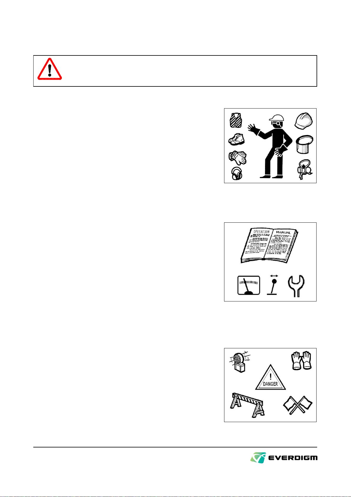
Know your equipments
Never fail to read and understand the safety messages, operation
manual and maintenance manual before installation and operation of the
grab. The operator who has been trained and licensed should only
operate the carrier and the grab. Familiarize yourself with the operating
especially safety related devices such as safety lock, emergency stop
and the others.
Figure 2
Know the work site
Before beginning operation, check in and around the work site for any
unusual conditions that could be dangerous and prepare the appropriate
warnings for safe work.
Be careful, especially when work in the vicinity of electric power line,
buried gas lines or oil tank. And pay your careful attention to the people
and the cars reside and passing near to the work site. Prepare for every
possible injury and damages.
Figure 3
- 6 -
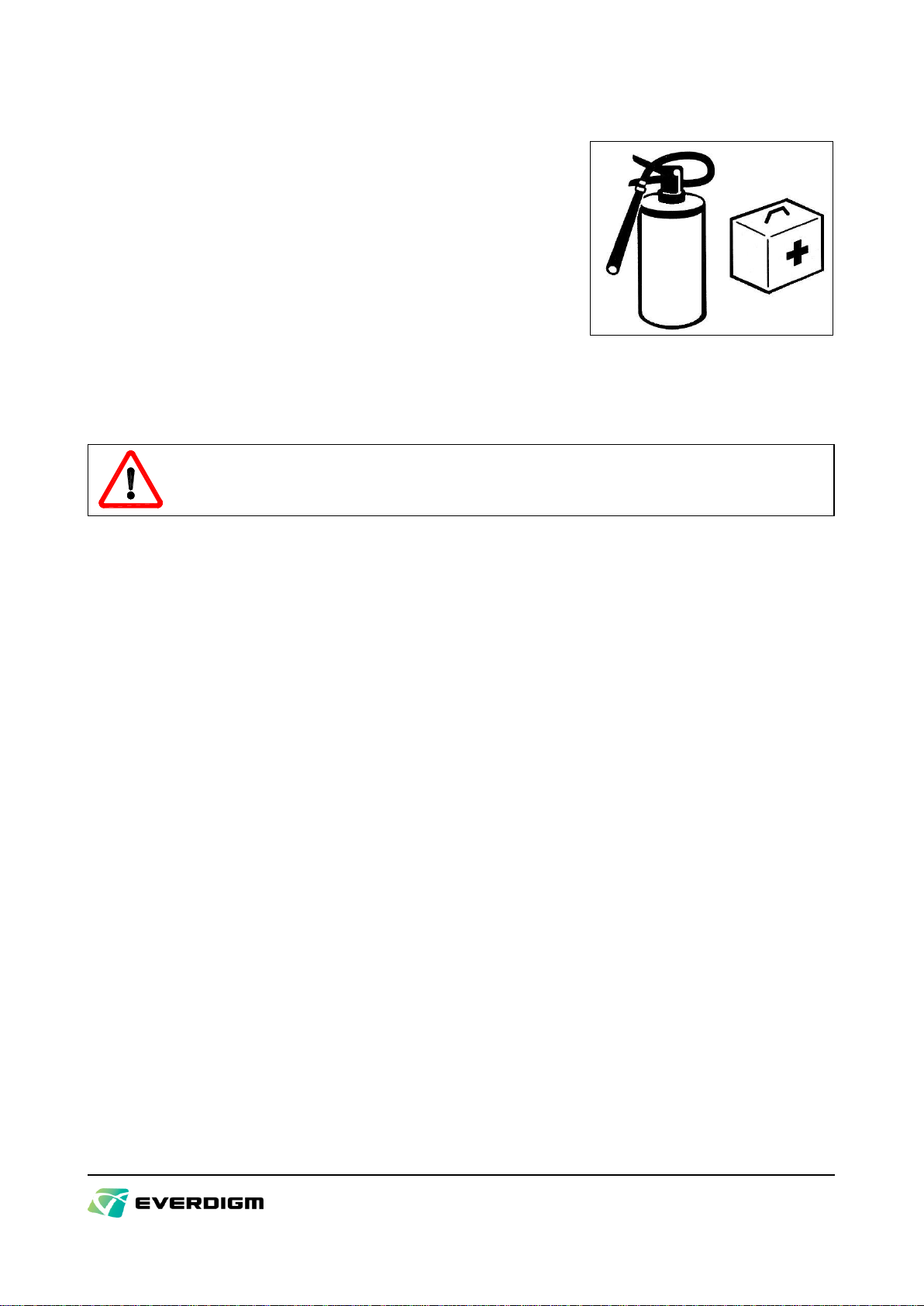
Know the rules
Every people who operate or maintain the equipment should know the
meaning, rules and laws in terms of equipment handling. They should
know also the traffic rules, fire service act, emergency measures and
where the relief equipment is.
Keep the fire extinguisher and the first-aid case in the operator‟s cabin
for emergency use.
Figure 4
1.2. Preparation for safe operation
WARNING!
Read and observe the following instructions on safety.
Install the grab on the suitable carrier
The suitable carrier must be selected taking the weight and hydraulic system of the grab into consideration.
The carrier may fall over if the grab is installed on the carrier, which does not fit the grab. All hydraulic lines
for the grab use must satisfy the specification and quality provided in page 15, “5.2. Requirements on the
carrier“.
Protect the operator from the flying splinters
To protect the operator from the heavy concrete elements falling down when the grab is working on the tall
columns, supports and brick, the carrier should be equipped with the cab protector strong enough for the
falling elements. For more information on the cab protector, please consult carrier manufacturer or
EVERDIGM dealer.
Safety instructions on the grab installation
When insert the mounting pin to install the grab on the carrier, the pin holes in the carrier‟s arm must be flush
with those in the mounting adapter of the grab. For this job, an carrier operator and an assistant should be
careful and agree on the hand signals beforehand. Your finger or hand must not used to check whether the
holes are flush. Once the mounting pins are inserted, lock the pins so that they are not taken off.
If quick coupler is used, be sure clamping is completed. When you connect the hose, tighten the connectors
with prescribed torques.
And make sure of complete connection when you open the stop valve. It may cause personal injury if the
incorrectly connected hose is pressurized. When connecting the hose, be careful not to have the o-ring
damaged or missed, and keep all the connectors clean.

- 7 -
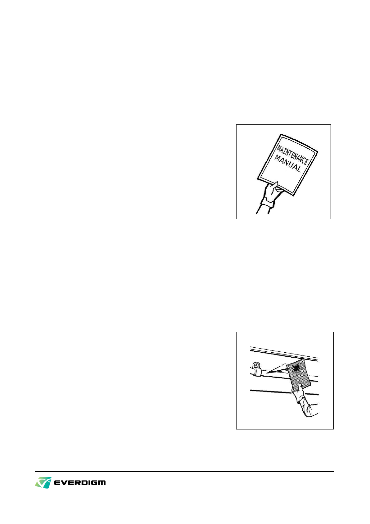
Check the grab and carrier
Please check every necessary parts of the grab and the
carrier before starting operation. Referring to check points in
the manuals of the grab and carrier, check any damages,
breakage, crack, wear, deformation, connections, oil leak
and the safety related points.
For the grab, check carefully crack in the welded parts of
grab body, bolt and nut, pin, oil leak on the cylinder and
hose. Do not operate in case any damages or failure is
found until it is fixed. In case such trouble is found, put the
warning tag in the driver cab. It is good to let the same
person remove the tag after trouble shooting. (Figure 5)
Figure 5
Check safety in work site
Check if the building has a sufficient load capacity to bear the weight of the carrier in case it is necessary to
work on the roof or ceiling of the building.
1.3. Safety information for operating the grab
WARNING!
The following instructions are on safety in operation with grab. Read, understand and observe
the instructions. More information is provided in page 23, “6.3. Operation”.
Never operate in unallowed applications
Operation in applications not allowed by the manufacturer must not be carried out. Refer to page 23, “6.3.
Operation”for such applications.
Operate from the top downwards
Heavy broken concrete elements may fall down and damage the hydraulic grab and the carrier, therefore,
columns and supports must be broken from the top downwards.
Never use for hammering or ramming
Hammering or ramming with the grab may cause serious damage to the grab.
Prepare a escape for the carrier
Never fail to prepare a escape for the carrier for emergency. The direction needs to be opposite to the object
of crushing and it should be straight way.
Stop operation on finding uncertainties
Never fail to stop the operation if an uncertain noise or vibration is detected during the operation and check
the condition of the carrier and the grab.
- 8 -
Pay attention during operation
Do not read, do not listen to music, do not talk over the cell phone during the operation. Do not operate the
grab as well as the carrier carelessly.
1.4. Safety information for maintenance of the grab
Follow the manual
Follow the instructions described in the manual when performing
maintenance work on the grab. Pay your careful attention to all relevant
safety regulations. Do not hurry. Most of accidents occur when the
instructions are not observed.
Use proper tools
The proper tools should be used for the maintenance work. Use of
improper tools may cause personal injury or damage to the parts of the
grab. Wear the eye protective glasses especially when removing and
replacing the cutter blades because the metal chips may fly off and
cause injury if they are struck with a hand hammer made of steel.
Figure 6
Use only the lug provided and sufficiently powerful lifting equipment when lifting the grab. Lug and ropes
must be in good condition.
Ensure that the grab and carrier stop completely
Maintenance work should be performed with the grab completely closed. Make sure to shut-off the stop valve
of the hydraulic line for the grab or to use a support to sustain the opened grab if maintenance work should
be carried out with the grab opened.
Place the carrier on the firm and flat ground with all the control levers or switches in a safe position.
Pay attention to hot oil and high pressure in hydraulic system
Special attention is required when performing maintenance of hydraulic
system. Never disassemble the grab as soon as the grab has been
stopped because the hydraulic system is still in high pressure. Follow the
instructions and release the residual pressure in the system. Pressure
may remain in the speed up valve, and it may be burst if it is
disassembled with the pressure inside.
Oil running out from the crack or small hole on hydraulic system may
cause personal injury. The hydraulic oil becomes very hot. And
compressed air in the oil tank may cause oil spouting when
disconnecting the line. Bleed off the compressed air by opening slowly
the filer cap of the oil tank.
Figure 7

- 9 -
Wet ground may be slippery
The oil wet on the ground may be very slippery. Collect any oil and dispose it correctly.
Do not alter or modify
Unauthorized alteration or modification of the grab shall not be guaranteed by EVERDIGM.
- 10 -
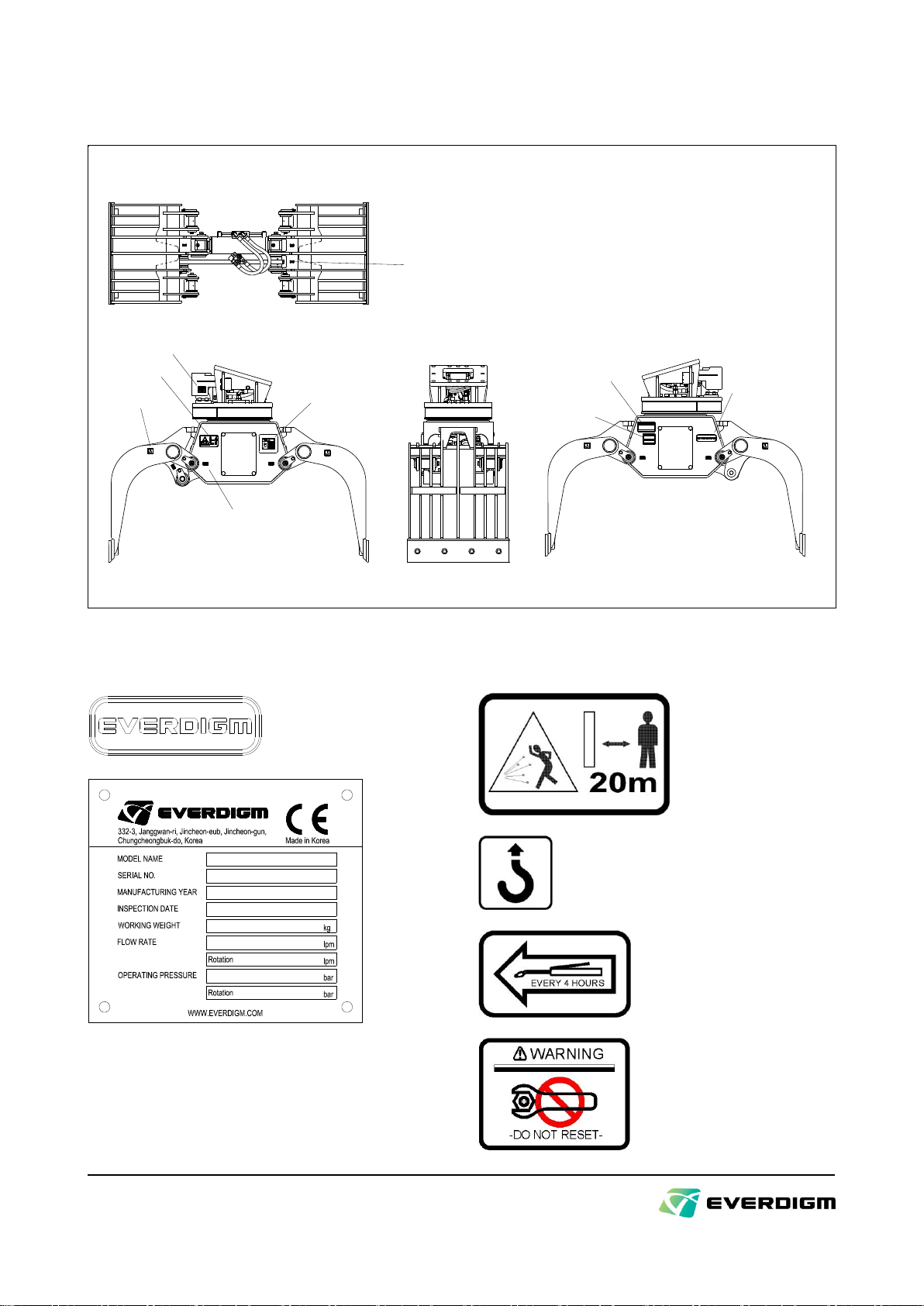
2. Configuration and ordering information
2.1. Main components
MA/MB : Open & Close Grab
RA/RB : Rotation
Port (MB)
Port (RB)
Cylinder
Main Frame Ass'y
Blade
Grab
Main Frame
Mounting Frame Body
Slewing Bearing
Slewing Motor,
Motor Control Block
Rotary Joint
Mounting Frame Ass'y
Port (RA)
Port (MA)
Link
Figure 8
The followings are to be supplied as standard parts :
Grab ass‟y
Standard tool kit
Operation manual
Parts list
Standard accessories
(fittings, hoses, etc)
2.2. Option components
The following parts are to be supplied as option only
Standard mounting adapter 1) (can be installed on most popular carriers)
Mounting pin & bush set 1)
Special tools for cylinder maintenance
Piping kit 2) (including the hydraulic rotation circuit)
Bolt and nut set for assembly of blades
Bolt and nut set for assembly of cover plates
Notes :
1) Installation must be confirmed whether it is possible in accordance with the carrier dimension.
Consult it with EVERDIGM dealer.
2) Refer to page 17, “5.3. Installation of hydraulic piping on the carrier“for more information

- 11 -
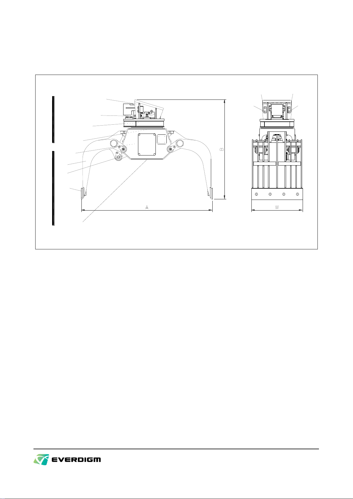
2.3. Mounting dimension for the adapter plate
EPG05
EPG08
Figure 9
190190
430
400
160 100100
25
20
Figure 10

- 12 -
3. Technical specifications
Model
EPG05
EPG08
Rib Type
Perforated Type
Rib Type
Perforated Type
Weight 1)
kg
432
419
568
548
Height of opened grab(B)
mm
1,162
1,162
1,303
1,303
Width of grab shells(W)
mm
600
600
700
700
Width of opened grab(A)
mm
1,533
1,533
1,736
1,736
Oil flow
lpm
20 ~ 60
Max. Operating Pressure
bar
300
Max. Oil Flow for Rotation
lpm
20
Max. Pressure for Rotation
bar
140
Max. Rotation Speed
rpm
15
Rotating Angle
> 360°(Continuous)
Operating Oil Temperature
°C
-20 ~ +90
Recommended Carrier Weight 2)
tonne
4 ~ 8
7 ~ 10
Hose Connections
Main
Pressurizing Port „MA‟: Grab Closing
Pressurizing Port „MB‟: Grab Opening
Rotation
(at the view from carrier)
Pressurizing Port „RA‟: Counter-clockwise
Pressurizing Port „RB‟: Clockwise
Type of Hose Connection Ports )
Main (Port „MA‟and „MB‟)
BSP 3/8
BSP 1/2
Rotation (Port „RA‟and „RB‟)
BSP 3/8
BSP 1/2
Notes :
1) Total weight excluding mounting adaptor, hydraulic hoses, fittings and mounting pins.
2) The carrier weight must be heavier in case long boom and/or long arm are equipped. For more details, consult
the manufacturer of the carrier.
3) JIS B2351 type „O‟O-ring boss ports.
- 13 -
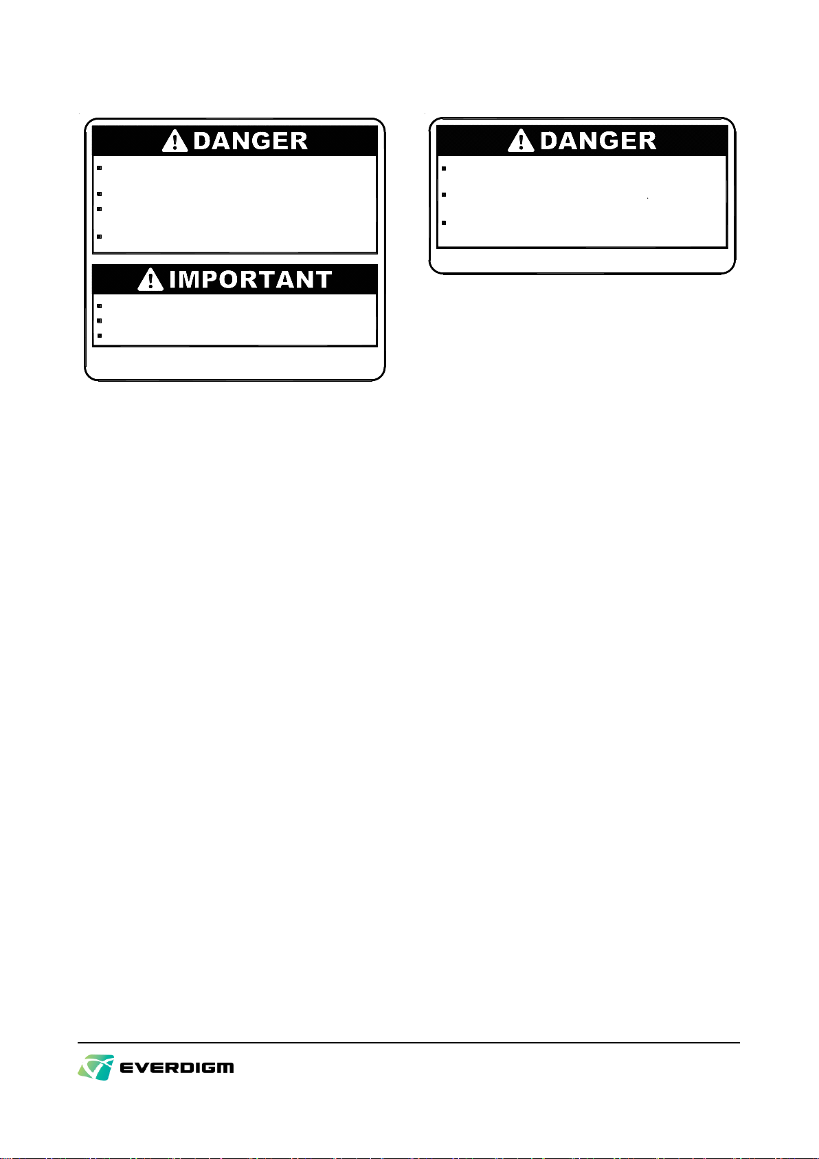
4. Markings and labels
Do Not Reset Risk of Serious
Injury
Causion in
Operation
EVERDIGM Logo
Greasing Port
최초 사용 전 반드시 취급설명서를 숙독하고, 필히 안전 지침을
준수하여 주십시오.
점검 및 정비 주기를 준수하여 주십시오.
절대 허용되지 않은 용도로 그라플을 사용하지 마십시오.
지정된 시간마다 지시부에 그리이스를 주입하십시오.
A095-0131
작업반경 내에 사람이 있을 경우 즉시 작동을 멈추십시오.
그라플 작업시 반드시 운전실 내에서 운전하여 주십시오.
운전실에는 안전망, 안전유리 등 보호 장비를 갖추십시오.
Greasing Port
Lifting Point CE Label
Stay Clear
그라플 작동 후 작동유가 매우 뜨거우므로 화상을 입을 수
있습니다. 제품 정비시 식을 때까지 충분히 기다리십시오.
A095-0100
실린더내에는 높은 압력이 남아 있을 수 있습니다.
함부로 분해하면 폭발할 수 있으므로 주의하십시오.
호스를 분해하기 전에 반드시 그라플을 완전히 닫아 주십시오.
그라플이 닫혀 사망 또는 중상을 입을 수 있습니다.
하십시오.
정비할 때에는 그라플이 움직이지 않도록 확실하게 고정
열린 그라플 안으로 신체 일부를 절대 넣지 마십시오.
Figure 11
Pay attention to the marks and labels related to safety.
EVERDIGM Logo
CE Label
Stay Clear
Indicates that the
distance must be kept
to be safe from the
flying rock splinter
Lifting Point
Indicates the hooking points when
lifting the grab
Greasing Port
Indicates grease apply
point. Apply grease at the
interval prescribed
Do not reset
Indicate “do not reset the
slewing motor control
valve”.
- 14 -
Caution in Operation
Be sure to secure the attachment prior to maintenance.
Follow all maintenance schedules.
Keep out from the attachment when it's moving parts
opened. Risk of accident!
A095-0132
Lubricate every greasing point at the specified interval.
Never use for unallowed applications.
safety instructions.
Read the manuals prior to initial use and follow the
Do not operate when bystanders are in working area.
cab using the necessary window guarding.
The operator must be adequately protected within the
Risk of Serious Injury
Wait for machine cooling before any maintenance work.
Danger of explosion! Follow the instructions.
Oil can be very hot after operating. Risk of burns!
A095-0134
High pressure may remain in the cylinder
the moving parts completely. Danger of injury or death!
Never disassemble the hydraulic parts before closing
- 15 -
5. Installation
5.1. Lifting the grab
DANGER!
Be sure of observing the instructions below because they are related to safety
Move the grab with the grabs completely closed and hydraulic lines plugged.
When lifting the grab, use only the lug provided and sufficiently powerful lifting equipment.
Ropes and rugs must be in good condition.
5.2. Requirements on the carrier
WARNING!
Be sure of observing the instructions because they are related safety and the life of the grab
EVERDIGM hydraulic grab, EPG series is designed to be used with an hydraulic excavator. Refer to the
following points when deciding an excavator for the grab.
Carrier weight :
The excavator may fall over if the capacity is not good enough to use the grab or if it is equipped
with a long boom and/or a long reach arm. Proper excavator should be decided for use with the
grab or such long boom and arm.
Hydraulic system :
The hydraulic system of the carrier must be suitable for the grab. Low flow rate and pressure
results in slow working speed and low crushing force respectively. Check the specification of the
carrier.
For the hydraulic grab, the inner diameter of the hydraulic line must be correspond to page 12 “3.
Technical specifications“or bigger. If the inner diameter is small inadequately, back-pressure
increase and the hydraulic oil in the lines may be overheated.
Have the bigger line for the grab closing than the line for the grab opening.
The seamless steel tube with thickness of more than 4.5mm (schedule 80 or higher) must be used.
And the hose must satisfy SAE R11~14.
Generally speaking the hydraulic oil originally recommended for the carrier can be used for the
EVERDIGM hydraulic grab. However, since working with the hydraulic grab will heat the oil much
more than the usual excavation work, the viscosity of the oil must be checked. When the grab is
used continuously, the viscosity of the hydraulic oil should be 15~100 cSt at the whole operating
temperature range. For more details about hydraulic oil, refer to page 32, Chapter “7.4. Hydraulic
oil”
When installing the grab with no pre-filled oil in it, the grab‟s cylinders need a lot of oil. So you must
fill the oil by the proper level in oil tank after operating the grab two or three times.

- 16 -
Hydraulic system must have a proper cooling system in order the temperature of the hydraulic oil
not to exceed 90 °C (194 °F) which may cause damage to the grab as well as the carrier. If the
carrier‟s oil cooler is too small either the original cooler must be replaced with a larger one or an
auxiliary cooler must be installed.
Retrofitting from breaker piping to grab piping :
When retrofitting the breaker piping lines to grab piping lines, take the return line of the existing
breaker piping lines for the grab closing lines of the grab. If the return line of the existing breaker
lines is also installed for low pressure only, we recommend you to replace all the piping lines with
the adequate piping lines as required above and make the lines both supply and return lines to high
pressure lines. If the breaker supply line is taken for the grab opening line, relief valve on the
breaker supply line does not need to be reset. (But the setting pressure must be more than 230
bar)
For more detailed information, refer to EVERDIGM service center.
- 17 -
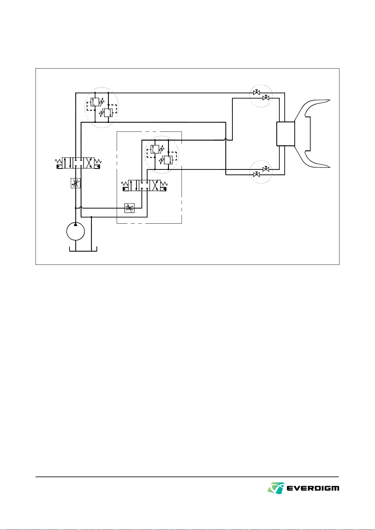
5.3. Installation of hydraulic piping on the carrier
Basic circuit for grab piping
RA
RB MB
MA
PT
PT
Relief Valves for
Grab Open/Close
Option Valve for Rotation
Stop Valves
Relief Valves for
Rotation
Stop Valves
Flow Control
Valve for Grab
Open/Close Flow Control
Valve for
Rotation
Figure 12
The following functions are required in the hydraulic circuit for the grab :
Relief valves to set the maximum pressure in grab opening and closing operation
Flow control valves to adjust working speed and rotation speed
(but, it is necessary not to exceed recommended speeds otherwise hydraulic motor and seals in it will be
damaged. Refer to page 12, “3. Technical specifications“)
Relief valves in hydraulic motor to set maximum pressure.
Stop-valves in the connection with the hose from the grab.
Standard piping kit for EVERDIGM EPG-series grab
By this kit, all of Grab opening, closing and rotating of the grab can be carried out with one spare valve of
the carrier. For more information, ask EVERDIGM dealer.

- 18 -
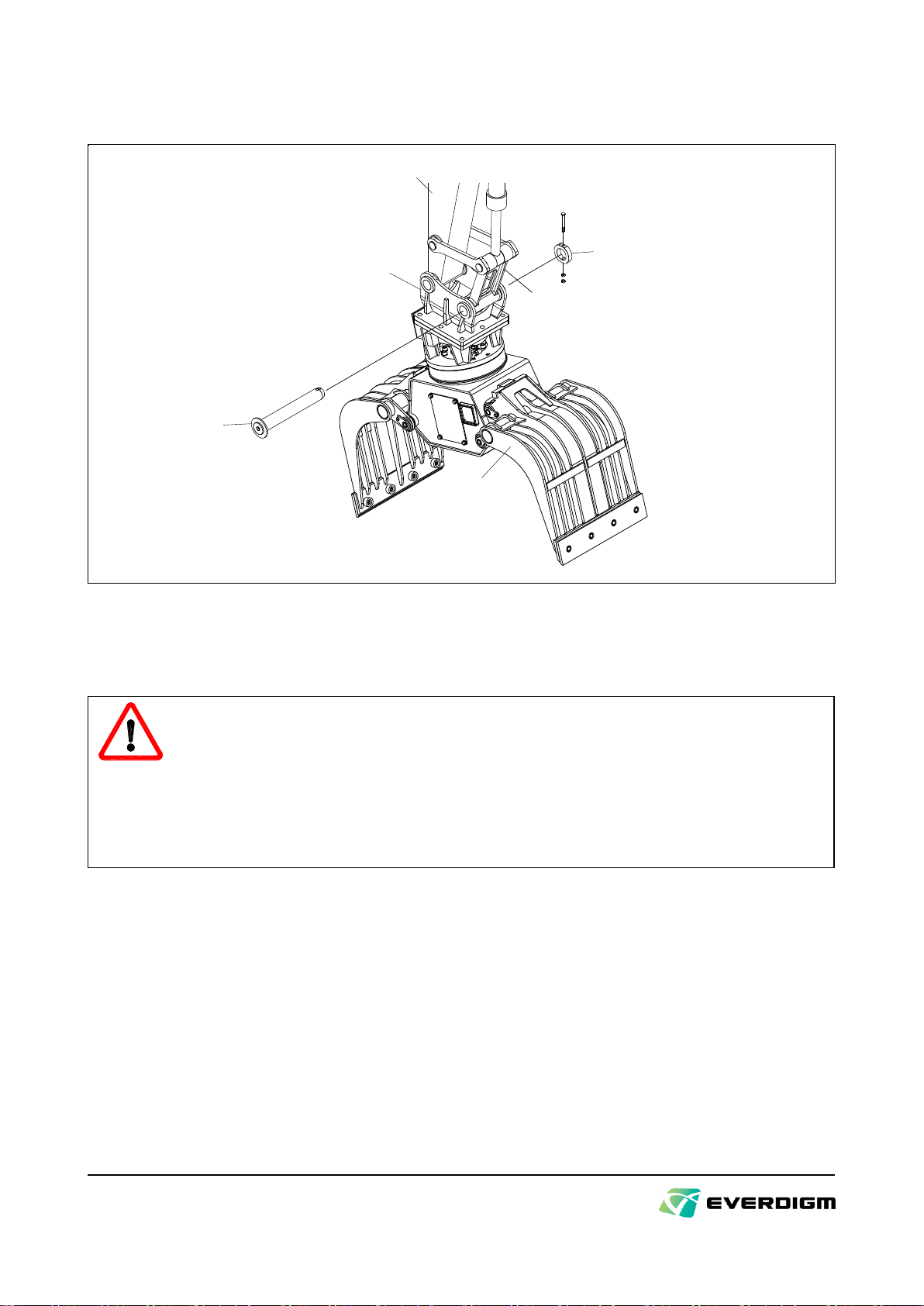
5.4. Mounting the hydraulic grab
Step 1 :
Stopper
Arm
Link
Mounting Adapter
Grab
Mounting Pin
Figure 13
Before mounting the grab, please put it on the flat place to take care of the direction of the mounting
adapter as the drawing.
Set the carrier‟s engine speed to low idle, and move the stick of carrier slowly until its hole is aligned with
that in the mounting adapter. Insert the mounting pin and assemble the stopper and its fasteners.
According to mounting adapter, the stopper and fasteners may not correspond exactly to Figure 13.
- 19 -
Step 2 :
Arm
Link
Mounting Adapter Stopper
Mounting Pin
Grab
Figure 14
Move the shovel cylinder and align the hole of carrier link with that in the mounting adapter in the same
way as the Step 1.
DANGER!
When aligning the pin holes, never insert fingers into the pin holes or the inner space of the
linkages. Unexpected movement of carrier may cause a server injury.
Match the holes by only visual lining up. While moving the carrier, make sure that there is no
person in the vicinity of the carrier.
Personal injury can result also from dropping the mounting pins during the installation work.
Wear safety shoes to protect feet.
Step 3 :
Remove the end caps from the connection ports on the grab and the stop valves on piping line, then
connect the main port and rotation port each other with proper hydraulic hoses.
The connecting threads must be undamaged and clean from sands, water, etc.
Open the stop valves on piping line.

- 20 -
5.5. Adjustment of the rotation device
Pressure Port(RA)
(Counter-clockwise Rotation)
Pressure Port(RB)
(Clockwise Rotation)
Pressure Relief Valve
for Motor
Built-in Relief Valve
(Look from direction A,B)
(A VIEW)
B
(B VIEW)
Stop Valve of
Main Line
Stop Valve of
Rotation Line
A
Figure 15
A built-in relief valve, in which a relief valve to protect rotation motor is built in EVERDIGM hydraulic grab
EPG-series. Do not reset this relief valve because it is set in the factory when delivery. If reset is required,
follow the instructions below.
A built-in relief valve will be seen as Figure 15.
Setting of the relief valve :
Port for pressure check is positioned in both ports „RA‟and „RB‟. Place a pressure gauge into either port,
and set the minimum pressure unscrewing the pressure relief valve to the end. The pressure gauge must
be for 400 bar or more.
Place the grab to the ground or the other strong structure so that the grab can not rotate.
Increase pressure by screwing the screw adjuster until the pointer of the pressure gauge reaches the
recommended pressure with the rotation actuator of the carrier switched on. Recommended pressure is
less than 100 bar.
Pay attention to the max pressure since motor life will be reduced if it is used over maximum pressure.
DANGER!
Pay attention to the safety in case a worker is vicinity of working area. Never operate the grab
with workers in close proximity to the grab.
IMPORTANT!
Do not reset the relief valve if possible. The rotation motor life will reduce if the pressure is set
exceeding the allowed pressure.
This manual suits for next models
1
Table of contents


