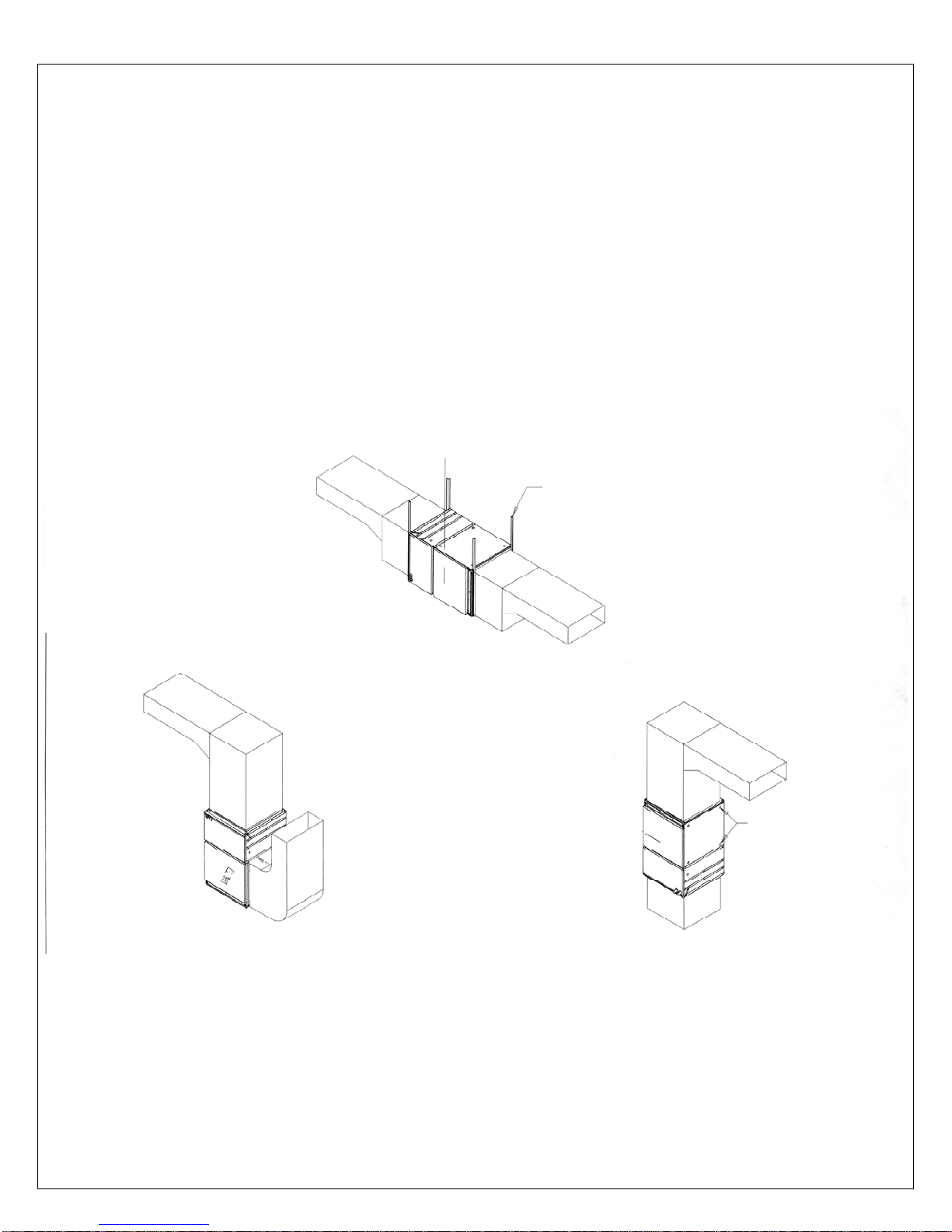
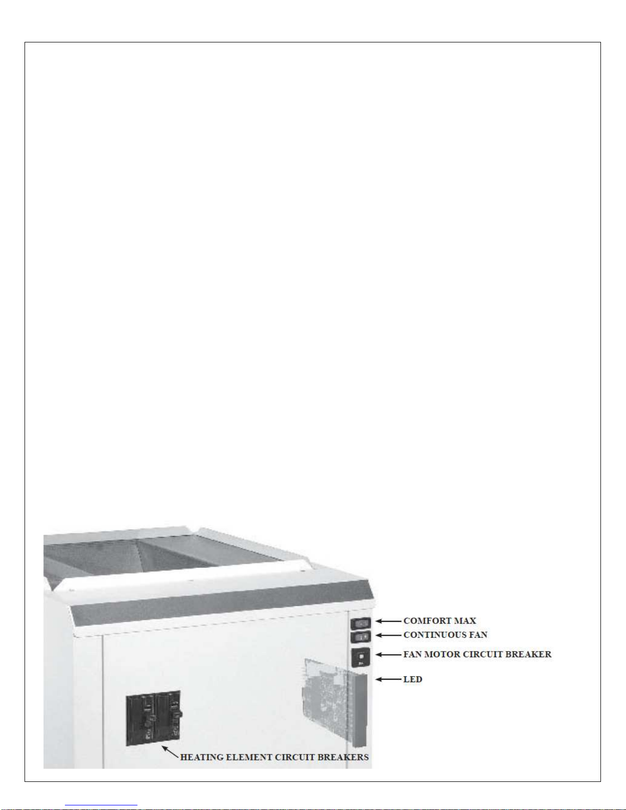
Granby KHE-00-G010-03 Setup guide
Other Granby Furnace manuals

Granby
Granby KLC-100 Setup guide

Granby
Granby max General instructions

Granby
Granby KLR-100 Setup guide

Granby
Granby KHM-100 GAS Setup guide

Granby
Granby 115 User manual

Granby
Granby KHM SERIES Instruction Manual

Granby
Granby KLC-088 User manual

Granby
Granby COMPACT- multi Instruction manual

Granby
Granby Conforto KLE 10 TO 27kW Setup guide

Granby
Granby KHM-1/090 Setup guide

Popular Furnace manuals by other brands

Armstrong
Armstrong EG7H SERIES Installation and maintenance instructions

Payne
Payne PG92ESA Installation, start-up, operating and service and maintenance instructions

SUPREME
SUPREME FEM10-M2301CM-A Installation instructions and homeowner's manual

Ingersoll-Rand
Ingersoll-Rand S9V2B080D4VSAC/D Installer's guide

Johnson Controls
Johnson Controls TM9T User's information manual

Fluke
Fluke 9118A user manual

Lennox
Lennox EL195UHE Elite Series Unit information

Intertherm
Intertherm M7RL Series user manual

HDG
HDG Pelletmaster 15 Operation manual

Pinnacle
Pinnacle Aero Bella AB-716C-QH User's manual and operating instructions

Nortek
Nortek MG2S Series installation instructions

VERDER
VERDER CARBOLITE GERO ABF 8/28 Installation, operation and maintenance instructions

Goodman
Goodman GMV9 Installation & operating instructions

SUPREME
SUPREME SUP10-M2301C Installation instructions and homeowner's manual

Dettson
Dettson AMT400B34-SM1PMA Installation instructions and homeowner's manual

Evcon
Evcon DGD 60 MBH installation instructions

Trane
Trane S8B1A026M2PSAB Installer's guide

Hart Sceintific
Hart Sceintific 9113 user manual