2
Section 1. Safety
Important - This document contains a wiring diagram
and service information. This is customer property and is
to remain with this unit. Please return to service informa-
tion pack upon completion of work.
Failure to follow this warning could result in property
damage, severe personal injury, or death.
Disconnect all electric power, Including remote disconnects
before servicing. Follow proper lockout/tagout procedures
to ensure the power cannot be inadvertently energized.
HAZARDOUS VOLTAGE!
Any attempt to repair a central air conditioning product
may result in property damage, severe personal injury,
or death.
These units use R-410A refrigerant which operates at
50 to 70% higher pressures than R-22. Use only
R-410A approved service equipment. Refrigerant
cylinders are painted a “Rose” color to indicate the type
of refrigerant and may contain a “dip” tube to allow for
charging of liquid refrigerant into the system. All R-410A
systems with variable speed compressors use a PVE
oil that readily absorbs moisture from the atmosphere
To limit this ‘hygroscopic“ action, the system should
remain sealed whenever possible. If a system has been
open to the atmosphere for more than 4 hours, the
compressor oil must be replaced. Never break a
vacuum with air and always change the driers when
opening the system for component replacement.
May cause minor to severe burning. Failure to follow this
Caution could result in property damage or personal injury.
Do not touch top of compressor.
REFRIGERANT OIL!
HOT SURFACE!
Failure to follow proper procedures can result in
personal illness or injury or severe equipment
damage.
System contains oil and refrigerant under high
pressure. Recover refrigerant to relieve pressure
before opening system.
CONTAINS REFRIGERANT!
Failure to inspect or use proper service tools may
result in equipment damage or personal injury.
Reconnect all grounding devices. All parts of this
product that are capable of conducting electrical
current are grounded. if grounding wires, screws,
straps, clips, nuts, or washers used to complete a
path to ground are removed for service, they must be
returned to their original position and properly
fastened.
GROUNDING REQUIRED!
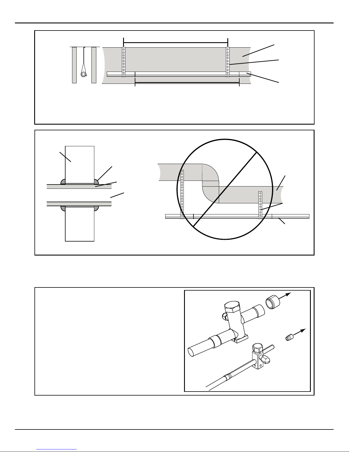
Failure to follow this warning will result in abrupt
release of system charge and may result in personal
injury and/or property damage. Extreme caution
should be exercised when opening the Liquid Line
Service valve. Turn valve stem counterclockwise only
until the stem contacts the rolled edge. No torque is
required.
SERVICE VALVES!
Failure to inspect lines or use proper service tools
may result in equipment damage or personal injury.
If using existing refrigerant lines make certain that all
joints are brazed, not soldered.
BRAZING REQUIRED!
Failure to follow this warning could result in property
damage, severe personal injury, or death.
Earth connection essential before connecting
electrical supply.
HIGH LEAKAGE CURRENT!
WARNING
CAUTION
CAUTION
WARNING
WARNING
WARNING
CAUTION
This information is intended for use by individuals
possessing adequate backgrounds of electrical and
mechanical experience. Any attempt to repair a central air
conditioning product may result in personal injury and/or
property damage. The manufacturer or seller cannot be
responsible for the interpretation of this information, nor
can it assume any liability in connection with its use.
CAUTION
WARNING